- Manuals
- Brands
- Hitachi Manuals
- Inverter
- WJ200 Series Software
- Instruction manual
-
Contents
-
Table of Contents
-
Bookmarks
Quick Links
HITACHI WJ BASIC INSTRUCTION MANUAL
DH PROGRAM #27
Detroit Hoist & Crane LLC, Co.
6650 Sterling Drive North, Sterling Height Michigan 48312
+1 586-268-2600
Page 1
Related Manuals for Hitachi WJ200
Summary of Contents for Hitachi WJ200
-
Page 1
HITACHI WJ BASIC INSTRUCTION MANUAL DH PROGRAM #27 Detroit Hoist & Crane LLC, Co. 6650 Sterling Drive North, Sterling Height Michigan 48312 +1 586-268-2600 Page 1… -
Page 2
Stop Read First! Important! – This manual is for program number #27 from Detroit Hoist. Please verify the program number before using this manual by navigating to VFD parameter d024. To navigate to d024 and check your VFD’s program number follow the steps chart below. Step Instruction Power up the VFD. -
Page 3: Table Of Contents
Contents BASIC SPECIFICATIONS …………………………….4 POWER CIRCUIT WIRING …………………………….5 CONTROL CIRCUIT WIRING …………………………….6 CONFIGURING SPEED CONTROL METHOD ……………………….7 CONFIGURING SPEEDS / FREQUENCIES …………………………8 ACCELERATION / DECELERATION TIMES …………………………. 9 ALTERNATE ACCELERATION / DECELERATION TIMES ……………………..9 MICRO-SPEED FUNCTION …………………………….
-
Page 4: Basic Specifications
BASIC SPECIFICATIONS For specifications that are not listed please contact Detroit Hoist for further information. Input power 3-phase 50/60hz (recommended). • Single phase applica�ons must derate VFD to 70% and may require a larger VFD to supply the required motor current. •…
-
Page 5: Power Circuit Wiring
POWER CIRCUIT WIRING Risk of electric shock! Risk of electric shock! • Before inspecting the inverter, be sure to turn off • Before inspecting the inverter, be sure to turn off the power supply and wait for more than 10 or 15 the power supply and wait for more than 10 or 15 minutes depending on the invertor model minutes depending on the invertor model…
-
Page 6: Control Circuit Wiring
CONTROL CIRCUIT WIRING Below is a basic example of the control circuit for the Hitachi WJ with the DH firmware and may differ from the actual configuration please reference the provided electrical drawing. Please consult Detroit Hoist if you plan to make changes to the control circuit for specific functions to ensure compatibility with the DH firmware.
-
Page 7: Configuring Speed Control Method
CONFIGURING SPEED CONTROL METHOD Detroit Hoist VFD controls come factory pre-configured for 2-Step speed control unless otherwise specified during the ordering process. Use the chart below to configure the speed control method that is required. Speed Control Method Parameters Values 2-Step P108 2-Step Infinitely Variable…
-
Page 8: Configuring Speeds / Frequencies
CONFIGURING SPEEDS / FREQUENCIES Speed / frequency values are stored as whole numbers (example is 15.25 Hz = 1525). Use the chart below to configure the speeds / frequencies for the configured speed control method. If operating at frequencies below or at 5hz for an extended amount of time an external motor cooling device may be required to prevent motor overheating.
-
Page 9: Acceleration / Deceleration Times
ACCELERATION / DECELERATION TIMES Changing the acceleration time to a shorter time can cause a E01, E02, or E03 over-current and or E05 over-load fault /trip, if this occurs due to a short acceleration time increase the acceleration time and test again. Changing the deceleration time to a shorter time can cause a E07 over-voltage fault/trip, if this occurs due to a short deceleration time increase the deceleration time and test again.
-
Page 10: Micro-Speed Function
MICRO-SPEED FUNCTION Micro-speed is designed to temporarily restrict the speed of the hoist to a lower speed and to prevent high speed operations until the function is released. The micro-speed function can be configured two ways. 2-STEP MAINTAINED MODE – This mode will switch to a 2-Step maintained speed set. This is helpful where the micro-speeds need to be specific.
-
Page 11: Auto-Speed 90Hz Function
AUTO-SPEED 90HZ FUNCTION The auto-speed function will allow the VFD to increase the high speed to up to 90Hz when there is an empty hook or a light load. You can set this function for automatic or for input activation. The auto-speed function is not available when using 0-10V/4-20mA speed control methods, when micro-speed is active, and or when in tandem mode.
-
Page 12: 125% Field Load Testing / Over-Weight Bypass
125% FIELD LOAD TESTING / OVER-WEIGHT BYPASS Each hoist is factory load tested prior to shipment. If a field load test is required, you will need to bypass the over-weight signal. To bypass the over-weight signal, locate the bypass terminal knife disconnect it should be labeled “BPS” (use images below as reference) and pull the yellow/orange tab to open.
-
Page 13: Hoist Over-Weight Function
HOIST OVER-WEIGHT FUNCTION The VFD is setup to use the output current to the motor as the over-weight function. The VFD uses (2) over-weight current parameters. Over-weight (1) is when operating less than or equal to the low-speed frequency and over-weight (2) is when operating above low-speed frequency.
-
Page 14: Setting Hoist Over-Weight
SETTING HOIST OVER-WEIGHT Each hoist’s over-weight settings will be set at the factory prior to shipment. In some cases, field adjustments may be required. Use the step chart below to set the hoist’s over-weight settings. Step Instruction Locate the terminal knife disconnect labeled “BPS” and pull the top of the yellow/orange tab outwards, this will bypass the over-weight circuit.
-
Page 15: Carrier Frequency
CARRIER FREQUENCY The carrier frequency is adjustable from 2.0kHz to 15kHz. The audible sound decreases at the higher frequencies, but RFI noise and leakage current may be increased. It is recommended that the carrier frequency is 2.3kHz or greater when operating in sensorless vector A044 = 03.
-
Page 16: Reset Fault Using Input
RESET FAULT USING INPUT Resetting a fault remotely using an input to the VFD can be done by configuring one of the available digital inputs for reset. Use the chart below. Function Parameters Value Fault reset C006 – C007 18 = RS OUTPUT SIGNAL WHEN FAULT OCCURS You can configure a 24v digital output to turn on when a fault occurs.
-
Page 17: Motor Brake Parameters
MOTOR BRAKE PARAMETERS The motor brake parameters ca be adjusted based on the application needs. Brake wait time for release – After the Brake Release Frequency Setting is reached, the inverter waits for the braking wait time (b121) Brake wait time for acceleration – The inverter waits for the Brake Wait Time for Acceleration (b122), and then starts accelerating the motor up to the set acceleration frequency.
-
Page 18: Constant Torque Control Mode / Manual Torque Boost
CONSTANT TORQUE CONTROL MODE / MANUAL TORQUE BOOST Manual Torque Boost – The Constant and Variable Torque algorithms feature an adjustable torque boost curve. When the motor load has a lot of inertia or starting friction, you may need to increase the low frequency starting torque characteristics by boosting the voltage above the normal V/f ratio (shown below).
-
Page 19: Constant Torque Control Mode / Automatic Torque Boost
CONSTANT TORQUE CONTROL MODE / AUTOMATIC TORQUE BOOST In constant torque using automatic torque boost the starting torque boost value and frequency break point are used as starting points for automatic torque boost. Voltage compensation gain and slip compensation gain are used for fine tuning adjustments. Using parameters A046 and A047, you can obtain better performance under automatic torque boost mode (A041=01).
-
Page 20: Sensorless Vector Control Mode
SENSORLESS VECTOR CONTROL MODE Sensorless vector control can achieve high torque performance (200% torque at 0.5Hz of output frequency) without motor speed feedback (encoder feedback). Sensorless vector control enables the inverter to accurately operate the motor with a high starting torque, even at low speed.
-
Page 21: Fine Tuning Sensorless Vector
FINE TUNING SENSORLESS VECTOR In most cases fine tuning is not required with the standard motor constants that are supplied when selecting the correct motor constant profile in parameter H003. Before making adjustments, try selecting a motor constant profile (1) smaller or larger than the combined connected motors in kW’s in parameter H003.
-
Page 22: Auto-Tuning
AUTO-TUNING In some cases, performing an auto-tune to get the proper motor constant will help in providing optimal performance when operating in sensorless vector control mode A044 = 03. Before auto-tuning make sure that parameter H003 is set to a value of the combined connected motors in kW’s, in some cases this value might be (1) size larger or smaller.
-
Page 23: Reduced Load Swing
REDUCED LOAD SWING In traverse applications it is possible to reduce the chance of load swing by configuring the VFD for sensorless vector control and using the torque limits to help reduce starting load swing. Also, you will use the alternate acceleration and deceleration functions to reduce load swing when accelerating and decelerating to and from high speeds.
-
Page 24: Tandem Hoist / Trolley Ezcom (Speed / Command Syncing)
TANDEM HOIST / TROLLEY EZCOM (SPEED / COMMAND SYNCING) Tandem hoist / trolley EZCOM can be used when 2 hoists / trolleys are used in tandem operation and require the frequency, command status, and run status to sync between each hoist. The VFD’s will need to be configured to communicate between each other and the internal logic activated.
-
Page 25: Ezcom Setup Guide
EZCOM SETUP GUIDE Step Instruction Configure the VFD’s parameters using the EZCOM parameter chart. Most of the parameters should already be configured and only the ones highlighted in yellow should need to be changed. Power down both VFD’s and connect the 2-wire shielded cable to the corresponding SN & SP terminals as shown in the EZCOM circuit wiring example on the next page.
-
Page 26: Ezcom Circuit Wiring
EZCOM CIRCUIT WIRING EZCOM wiring example circuit. Make sure the BVFD has the RS485 termination resistor dip switch toggled to the right. MDSW1 Dip switch for termination RS-485 (Modbus) Page 26…
-
Page 27: View Fault History
VIEW FAULT HISTORY To view the fault history, use the step chart below. Step Instruction Power on the VFD. Press ESC button and use the arrow buttons to navigate to d081 – d086. Press the SET button to view the fault. NOTE d081 will always be the most recent fault.
-
Page 28: Clearing Fault History
CLEARING FAULT HISTORY To clear the fault history, use the step chart below. Step Instruction Power on the VFD. Press the ESC button 4 times or until the screen displays b001. Use the arrow buttons to navigate to parameter b084. Press the SET button to enter the parameter, use the UP arrow to set the value to 01 and press the SET button to save the change.
-
Page 29: Fault / Error Codes Description
FAULT / ERROR CODES DESCRIPTION Fault / Error Code Description Over-current event while at constant speed Over-current event during deceleration Over-current event during acceleration Over-current event during other conditions Electronic thermal overload protection (motor current > b012) Dynamic braking resistor over used error. Check incoming voltage for spikes. DC-Bus over-voltage error.
-
Page 30
REVISIONS Version Date Changes / Updates 1/7/2022 Initial release Page 30…
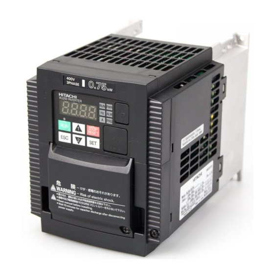
![]()
WJ200 Series Inverter
Quick Reference Guide
|
• |
Single-phase Input |
200V class |
|
• |
Three-phase Input |
200V class |
|
• |
Three-phase Input |
400V class |
|
Manual Number: NT3251AX |
Refer to the user manual for detail |
March 2012
Hitachi Industrial Equipment Systems Co., Ltd.


UL® Cautions, Warnings and Instructions
Warnings and Cautions for Troubleshooting and Maintenance
(Standard to comply with : UL508C,CSA C22.2 No.14-05) Warning Markings
GENERAL:
These devices are open type Power Conversion Equipment. They are intended to be used in an enclosure. Insulated gate bipolar transistor (IGBT) incorporating microprocessor technology. They are operated from a single or three-phase source of supply, and intended to control three-phase induction motors by means of a variable frequency output. The units are intended for general-purpose industrial applications.
MARKING REQUIREMENTS:
Ratings — Industrial control equipment shall be plainly marked with the Listee’s name, trademark, File number, or other descriptive marking by which the organization responsible for the product may be identified;
a)“Maximum surrounding air temperature rating of 50 ºC.”
b)“Solid State motor overload protection reacts with max. 150 % of FLA”.
c)“Install device in pollution degree 2 environment.”
d)“Suitable for use on a circuit capable of delivering not more than 100,000 rms Symmetrical Amperes, 240 or 480 Volts Maximum.”
e)“When Protected by CC, G, J or R Class Fuses.” or “When Protected By A Circuit Breaker Having An Interrupting Rating Not Less Than 100,000 rms Symmetrical Amperes, 240 or 480 Volts Maximum.”
f)“Integral solid state short circuit protection does not provide branch circuit protection. Branch circuit protection must be provided in accordance with the National Electrical Code and any additional local codes.”
1

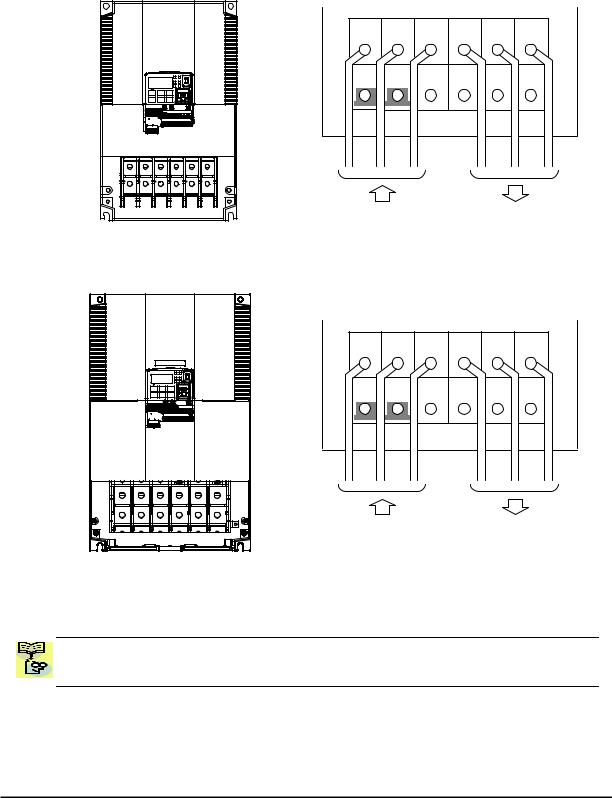
Terminal symbols and Screw size
|
Inverter Model |
Screw Size |
Required |
Wire range |
||||||
|
Torque (N-m) |
|||||||||
|
WJ200-001S |
M3.5 |
1.0 |
AWG16 (1.3mm2) |
||||||
|
WJ200-002S |
|||||||||
|
WJ200-004S |
|||||||||
|
WJ200-007S |
M4 |
1.4 |
AWG12 (3.3mm2) |
||||||
|
WJ200-015S |
M4 |
1.4 |
AWG10 (5.3mm2) |
||||||
|
WJ200-022S |
|||||||||
|
WJ200-001L |
|||||||||
|
WJ200-002L |
M3.5 |
1.0 |
AWG16 (1.3mm2) |
||||||
|
WJ200-004L |
|||||||||
|
WJ200-007L |
|||||||||
|
WJ200-015L |
M4 |
1.4 |
AWG14 (2.1mm2) |
||||||
|
WJ200-022L |
M4 |
1.4 |
AWG12 (3.3mm2) |
||||||
|
WJ200-037L |
M4 |
1.4 |
AWG10 (5.3mm2) |
||||||
|
WJ200-055L |
M5 |
3.0 |
AWG6 (13mm2) |
||||||
|
WJ200-075L |
|||||||||
|
WJ200-110L |
M6 |
3.9 to 5.1 |
AWG4 (21mm2) |
||||||
|
WJ200-150L |
M8 |
5.9 to 8.8 |
AWG2 (34mm2) |
||||||
|
WJ200-004H |
AWG16 (1.3mm2) |
||||||||
|
WJ200-007H |
M4 |
1.4 |
|||||||
|
WJ200-015H |
|||||||||
|
WJ200-022H |
M4 |
1.4 |
AWG14 (2.1mm2) |
||||||
|
WJ200-030H |
|||||||||
|
WJ200-040H |
M4 |
1.4 |
AWG12 (3.3mm2) |
||||||
|
WJ200-055H |
M5 |
3.0 |
AWG10 (5.3mm2) |
||||||
|
WJ200-075H |
|||||||||
|
WJ200-110H |
M6 |
3.9 to 5.1 |
AWG6 (13mm2) |
||||||
|
WJ200-150H |
2

Fuse Sizes
Distribution fuse size marking is included in the manual to indicate that the unit shall be connected with a Listed Cartridge Nonrenewable fuse, rated 600 Vac with the current ratings as shown in the table below or Type E Combination Motor Controller marking is included in the manual to indicate that the unit shall be connected with,LS Industrial System Co.,Ltd,Type E Combination Motor Controller MMS Series with the ratings as shown in the table below:
|
Inverter Model |
Type |
Fuse Rating |
Type E CMC |
||||||||
|
WJ200-001S |
|||||||||||
|
WJ200-002S |
10A, AIC 200kA |
||||||||||
|
WJ200-004S |
MMS-32H,240V,40A |
||||||||||
|
WJ200-007S |
20A, AIC 200kA |
||||||||||
|
WJ200-015S |
30A, AIC 200kA |
||||||||||
|
WJ200-022S |
|||||||||||
|
WJ200-001L |
|||||||||||
|
WJ200-002L |
10A, AIC 200kA |
||||||||||
|
WJ200-004L |
|||||||||||
|
WJ200-007L |
15A, AIC 200kA |
MMS-32H,240V,40A |
|||||||||
|
WJ200-015L |
|||||||||||
|
WJ200-022L |
20A, AIC 200kA |
||||||||||
|
WJ200-037L |
Class J |
30A, AIC 200kA |
|||||||||
|
WJ200-055L |
60A, AIC 200kA |
||||||||||
|
WJ200-075L |
|||||||||||
|
MMS-100H,240V,80A |
|||||||||||
|
WJ200-110L |
80A, AIC 200kA |
||||||||||
|
WJ200-150L |
|||||||||||
|
WJ200-004H |
|||||||||||
|
WJ200-007H |
10A, AIC 200kA |
||||||||||
|
WJ200-015H |
|||||||||||
|
WJ200-022H |
MMS-32H,480V,40A |
||||||||||
|
WJ200-030H |
15A, AIC 200kA |
||||||||||
|
or |
|||||||||||
|
WJ200-040H |
|||||||||||
|
MMS-63H,480V,52A |
|||||||||||
|
WJ200-055H |
30A, AIC 200kA |
||||||||||
|
WJ200-075H |
|||||||||||
|
WJ200-110H |
50A, AIC 200kA |
||||||||||
|
WJ200-150H |
|||||||||||
3
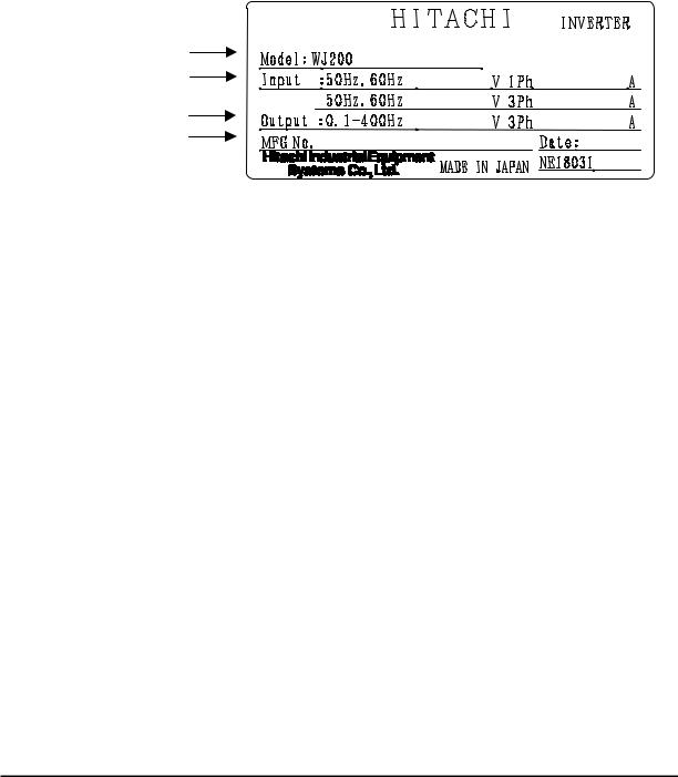
Inverter Specification Label
The Hitachi WJ200 inverters have product labels located on the right side of the housing, as pictured below. Be sure to verify that the specifications on the labels match your power source, and application safety requirements.
|
Model name |
-001SF |
Ver:2.0 |
|
|
Input ratings |
|||
|
200-240 |
2.0/1.3 |
||
|
Output ratings |
200-240 |
1.2/1.0 |
|
|
MFG number |
05A_T12345_A_-001 |
1005 |
|
Inverter Specification Label
The model number for a specific inverter contains useful information about its operating characteristics. Refer to the model number legend below:
|
WJ200 |
001 |
S |
F |
Configuration type |
||||||||||||
|
Series name |
||||||||||||||||
|
F=with keypad |
||||||||||||||||
|
Input voltage: |
||||||||||||||||
|
S=Single-phase 200V class |
||||||||||||||||
|
L=Three-phase 200V class |
||||||||||||||||
|
H=Three-phase 400V class |
||||||||||||||||
|
Applicable motor capacity in kW |
||||||||||||||||
|
001=0.1kW |
037=3.7kW |
|||||||||||||||
|
002=0.2kW |
040=4.0kW |
|||||||||||||||
|
004=0.4kW |
055=5.5kW |
|||||||||||||||
|
007=0.75kW |
075=7.5kW |
|||||||||||||||
|
015=1.5kW |
110=11kW |
|||||||||||||||
|
022=2.2kW |
150=15kW |
|||||||||||||||
|
030=3.0kW |
4

WJ200 Inverter Specifications
Model-specific tables for 200V and 400V class inverters
The following tables are specific to WJ200 inverters for the 200V and 400V class model groups. Note that “General Specifications” on page in this chapter apply to both voltage class groups. Footnotes for all specification tables follow the table below.
|
Item |
Single-phase 200V class Specifications |
||||||||||
|
WJ200 inverters, 200V models |
001SF |
002SF |
004SF |
007SF |
015SF |
022SF |
|||||
|
Applicable motor size |
kW |
VT |
0.2 |
0.4 |
0.55 |
1.1 |
2.2 |
3.0 |
|||
|
CT |
0.1 |
0.2 |
0.4 |
0.75 |
1.5 |
2.2 |
|||||
|
HP |
VT |
1/4 |
1/2 |
3/4 |
1.5 |
3 |
4 |
||||
|
CT |
1/8 |
1/4 |
1/2 |
1 |
2 |
3 |
|||||
|
Rated capacity (kVA) |
200V |
VT |
0.4 |
0.6 |
1.2 |
2.0 |
3.3 |
4.1 |
|||
|
CT |
0.2 |
0.5 |
1.0 |
1.7 |
2.7 |
3.8 |
|||||
|
240V |
VT |
0.4 |
0.7 |
1.4 |
2.4 |
3.9 |
4.9 |
||||
|
CT |
0.3 |
0.6 |
1.2 |
2.0 |
3.3 |
4.5 |
|||||
|
Rated input voltage |
Single-phase: 200V-15% to 240V +10%, 50/60Hz ±5% |
||||||||||
|
Rated output voltage |
Three-phase: 200 to 240V (proportional to input voltage) |
||||||||||
|
Rated output current (A) |
VT |
1.2 |
1.9 |
3.5 |
6.0 |
9.6 |
12.0 |
||||
|
CT |
1.0 |
1.6 |
3.0 |
5.0 |
8.0 |
11.0 |
|||||
|
Starting torque |
200% |
at 0.5Hz |
|||||||||
|
Braking |
Without resistor |
100%: ≤50Hz |
70%: ≤ 50Hz |
20%: ≤ 50Hz |
|||||||
|
50%: ≤60Hz |
50%: ≤ 60Hz |
20%: ≤ 60Hz |
|||||||||
|
With resistor |
150% |
100% |
|||||||||
|
DC braking |
Variable operating frequency, time, and braking |
force |
|||||||||
|
Weight |
kg |
1.0 |
1.0 |
1.1 |
1.6 |
1.8 |
1.8 |
||||
|
lb |
2.2 |
2.2 |
2.4 |
3.5 |
4.0 |
4.0 |
5

WJ200 Inverter Specifications, continued…
|
Item |
Three-phase 200V class Specifications |
||||||||||||
|
WJ200 inverters, 200V models |
001LF |
002LF |
004LF |
007LF |
015LF |
022LF |
|||||||
|
Applicable motor size |
kW |
VT |
0.2 |
0.4 |
0.75 |
1.1 |
2.2 |
3.0 |
|||||
|
CT |
0.1 |
0.2 |
0.4 |
0.75 |
1.5 |
2.2 |
|||||||
|
HP |
VT |
1/4 |
1/2 |
1 |
1.5 |
3 |
4 |
||||||
|
CT |
1/8 |
1/4 |
1/2 |
1 |
2 |
3 |
|||||||
|
Rated capacity (kVA) |
200V |
VT |
0.4 |
0.6 |
1.2 |
2.0 |
3.3 |
4.1 |
|||||
|
CT |
0.2 |
0.5 |
1.0 |
1.7 |
2.7 |
3.8 |
|||||||
|
240V |
VT |
0.4 |
0.7 |
1.4 |
2.4 |
3.9 |
4.9 |
||||||
|
CT |
0.3 |
0.6 |
1.2 |
2.0 |
3.3 |
4.5 |
|||||||
|
Rated input voltage |
Three-phase: 200V-15% to 240V +10%, 50/60Hz ±5% |
||||||||||||
|
Rated output voltage |
Three-phase: 200 to 240V (proportional to input voltage) |
||||||||||||
|
Rated output current (A) |
VT |
1.2 |
1.9 |
3.5 |
6.0 |
9.6 |
12.0 |
||||||
|
CT |
1.0 |
1.6 |
3.0 |
5.0 |
8.0 |
11.0 |
|||||||
|
Starting torque |
200% at 0.5Hz |
||||||||||||
|
Braking |
Without resistor |
100%: ≤50Hz |
70%: ≤ 50Hz |
20%: ≤ 50Hz |
|||||||||
|
50%: ≤60Hz |
50%: ≤ 60Hz |
20%: ≤ 60Hz |
|||||||||||
|
With resistor |
150% |
100% |
|||||||||||
|
DC braking |
Variable operating frequency, time, and braking |
force |
|||||||||||
|
Weight |
kg |
1.0 |
1.0 |
1.1 |
1.2 |
1.6 |
1.8 |
||||||
|
lb |
2.2 |
2.2 |
2.4 |
2.6 |
3.5 |
4.0 |
|||||||
|
Item |
Three-phase 200V class Specifications |
||||||||||||
|
WJ200 inverters, 200V models |
037LF |
055LF |
075LF |
110LF |
150LF |
||||||||
|
Applicable motor size |
kW |
VT |
5.5 |
7.5 |
11 |
15 |
18.5 |
||||||
|
CT |
3.7 |
5.5 |
7.5 |
11 |
15 |
||||||||
|
HP |
VT |
7.5 |
10 |
15 |
20 |
25 |
|||||||
|
CT |
5 |
7.5 |
10 |
15 |
20 |
||||||||
|
Rated capacity (kVA) |
200V |
VT |
6.7 |
10.3 |
13.8 |
19.3 |
20.7 |
||||||
|
CT |
6.0 |
8.6 |
11.4 |
16.2 |
20.7 |
||||||||
|
240V |
VT |
8.1 |
12.4 |
16.6 |
23.2 |
24.9 |
|||||||
|
CT |
7.2 |
10.3 |
13.7 |
19.5 |
24.9 |
||||||||
|
Rated input voltage |
Three-phase: 200V-15% to 240V +10%, 50/60Hz ±5% |
||||||||||||
|
Rated output voltage |
Three-phase: 200 to 240V (proportional to input voltage) |
||||||||||||
|
Rated output current (A) |
VT |
19.6 |
30.0 |
40.0 |
56.0 |
69.0 |
|||||||
|
CT |
17.5 |
25.0 |
33.0 |
47.0 |
60.0 |
||||||||
|
Starting torque |
200% at 0.5Hz |
||||||||||||
|
Braking |
Without resistor |
20%: ≤50Hz |
|||||||||||
|
20%: ≤60Hz |
|||||||||||||
|
With resistor |
100% |
80% |
|||||||||||
|
DC braking |
Variable operating frequency, time, and braking |
force |
|||||||||||
|
Weight |
Kg |
2.0 |
3.3 |
3.4 |
5.1 |
7.4 |
|||||||
|
lb |
4.4 |
7.3 |
7.5 |
11.2 |
16.3 |
6

WJ200 Inverter Specifications, continued…
|
Item |
Three-phase 400V class Specifications |
||||||||||||
|
WJ200 inverters, 400V models |
004HF |
007HF |
015HF |
022HF |
030HF |
040HF |
|||||||
|
Applicable motor size |
kW |
VT |
0.75 |
1.5 |
2.2 |
3.0 |
4.0 |
5.5 |
|||||
|
CT |
0.4 |
0.75 |
1.5 |
2.2 |
3.0 |
4.0 |
|||||||
|
HP |
VT |
1 |
2 |
3 |
4 |
5 |
7.5 |
||||||
|
CT |
1/2 |
1 |
2 |
3 |
4 |
5 |
|||||||
|
Rated capacity (kVA) |
380V |
VT |
1.3 |
2.6 |
3.5 |
4.5 |
5.7 |
7.3 |
|||||
|
CT |
1.1 |
2.2 |
3.1 |
3.6 |
4.7 |
6.0 |
|||||||
|
480V |
VT |
1.7 |
3.4 |
4.4 |
5.7 |
7.3 |
9.2 |
||||||
|
CT |
1.4 |
2.8 |
3.9 |
4.5 |
5.9 |
7.6 |
|||||||
|
Rated input voltage |
Three-phase: 400V-15% to 480V +10%, 50/60Hz ±5% |
||||||||||||
|
Rated output voltage |
Three-phase: 400 to 480V (proportional to input voltage) |
||||||||||||
|
Rated output current (A) |
VT |
2.1 |
4.1 |
5.4 |
6.9 |
8.8 |
11.1 |
||||||
|
CT |
1.8 |
3.4 |
4.8 |
5.5 |
7.2 |
9.2 |
|||||||
|
Starting torque |
200% at 0.5Hz |
||||||||||||
|
Braking |
Without resistor |
100%: ≤50Hz |
70%: ≤ 50Hz |
20%: ≤ 50Hz |
|||||||||
|
50%: ≤60Hz |
50%: ≤ 60Hz |
20%: ≤ 60Hz |
|||||||||||
|
With resistor |
150% |
||||||||||||
|
DC braking |
Variable operating frequency, time, and braking |
force |
|||||||||||
|
Weight |
kg |
1.5 |
1.6 |
1.8 |
1.9 |
1.9 |
2.1 |
||||||
|
lb |
3.3 |
3.5 |
4.0 |
4.2 |
4.2 |
4.6 |
|||||||
|
Item |
Three-phase 400V class Specifications |
||||||||||||
|
WJ200 inverters, 400V models |
055HF |
075HF |
110HF |
150HF |
|||||||||
|
Applicable motor size |
kW |
VT |
7.5 |
11 |
15 |
18.5 |
|||||||
|
CT |
5.5 |
7.5 |
11 |
15 |
|||||||||
|
HP |
VT |
10 |
15 |
20 |
25 |
||||||||
|
CT |
7.5 |
10 |
15 |
20 |
|||||||||
|
Rated capacity (kVA) |
380V |
VT |
11.5 |
15.1 |
20.4 |
25.0 |
|||||||
|
CT |
9.7 |
11.8 |
15.7 |
20.4 |
|||||||||
|
480V |
VT |
14.5 |
19.1 |
25.7 |
31.5 |
||||||||
|
CT |
12.3 |
14.9 |
19.9 |
25.7 |
|||||||||
|
Rated input voltage |
Three-phase: 400V-15% to 480V +10%, 50/60Hz ±5% |
||||||||||||
|
Rated output voltage |
Three -phase: 400 to 480V (proportional to input voltage) |
||||||||||||
|
Rated output current (A) |
VT |
17.5 |
23.0 |
31.0 |
38.0 |
||||||||
|
CT |
14.8 |
18.0 |
24.0 |
31.0 |
|||||||||
|
Starting torque |
200% at 0.5Hz |
||||||||||||
|
Braking |
Without resistor |
20%: ≤50Hz |
|||||||||||
|
20%: ≤60Hz |
|||||||||||||
|
With resistor |
150% |
||||||||||||
|
DC braking |
Variable operating frequency, time, and braking force |
||||||||||||
|
Weight |
kg |
3.5 |
3.5 |
4.7 |
5.2 |
||||||||
|
lb |
7.7 |
7.7 |
10.4 |
11.5 |
7

The following table shows which models need derating.
|
1-ph 200V class |
Need |
3-ph 200V class |
Need |
3-ph 400V class |
Need |
|
derating |
derating |
WJ200-004H |
derating |
||
|
WJ200-001S |
WJ200-001L |
||||
|
WJ200-002S |
WJ200-002L |
WJ200-007H |
|||
|
WJ200-004S |
WJ200-004L |
WJ200-015H |
|||
|
WJ200-007S |
WJ200-007L |
WJ200-022H |
|||
|
WJ200-015S |
WJ200-015L |
WJ200-030H |
|||
|
WJ200-022S |
WJ200-022L |
WJ200-040H |
|||
|
WJ200-037L |
WJ200-055H |
||||
|
WJ200-055L |
WJ200-075H |
||||
|
WJ200-075L |
WJ200-110H |
||||
|
WJ200-110L |
WJ200-150H |
||||
|
WJ200-150L |
|||||
|
need derating |
need no derating
Use the following derating curves to help determine the optimal carrier frequency setting for your inverter and find the output current derating. Be sure to use the proper curve for your particular WJ200 inverter model number.
8
![]()
Basic System Description
A motor control system will obviously include a motor and inverter, as well as a circuit breaker or fuses for safety. If you are connecting a motor to the inverter on a test bench just to get started, that’s all you may need for now. But a system can also have a variety of additional components. Some can be for noise suppression, while others may enhance the inverter’s braking performance. The figure and table below show a system with all the optional components you might need in your finished application.
Breaker,
MCCB or
GFI
L1 L2 L3
+1 
Inverter +
GND T1 T2 T3
From power supply
|
Name |
Function |
|
Breaker / |
A molded-case circuit breaker (MCCB), ground fault |
|
disconnect |
interrupter (GFI), or a fused disconnect device. NOTE: The |
|
installer must refer to the NEC and local codes to ensure |
|
|
safety and compliance. |
|
|
Input-side |
This is useful in suppressing harmonics induced on the |
|
AC Reactor |
power supply lines and for improving the power factor. |
|
WARNING: Some applications must use an input-side AC |
|
|
Reactor to prevent inverter damage. See Warning on next |
|
|
page. |
|
|
Radio noise filter |
Electrical noise interference may occur on nearby |
|
equipment such as a radio receiver. This magnetic choke |
|
|
filter helps reduce radiated noise (can also be used on |
|
|
output). |
|
|
EMC filter (for |
Reduces the conducted noise on the power supply wiring |
|
CE applications, |
between the inverter and the power distribution system. |
|
see Appendix D) |
Connect to the inverter primary (input) side. |
|
Radio noise filter |
This capacitive filter reduces radiated noise from the main |
|
(use in non-CE |
power wires in the inverter input side. |
|
applications) |
|
|
DC link choke |
Suppress harmonics generated by the inverter. However, it |
|
will not protect the input diode bridge rectifier. |
|
|
Radio noise filter |
Electrical noise interference may occur on nearby |
|
equipment such as a radio receiver. This magnetic choke |
|
|
filter helps reduce radiated noise (can also be used on |
|
|
input). |
|
|
Output-side |
This reactor reduces the vibration in the motor caused by |
|
AC Reactor |
the inverter’s switching waveforms, by smoothing the |
|
waveform to approximate commercial power quality. It is |
|
|
also useful to reduce harmonics when wiring from the |
|
|
inverter to the motor is more than 10m in length. |
|
|
LCR filter |
Sine wave shaping filter for output side. |

Determining Wire and Fuse Sizes
The maximum motor currents in your application determines the recommended wore size. The following table gives the wire size in AWG. The “Power Lines” column applies to the inverter input power, output wires to the motor, the earth ground connection, and any other components shown in the “Basic System Description” on page 9. The “Signal Lines” column applies to any wire connecting to the two green connectors just inside the front cover panel.
|
Motor Output |
Wiring |
Applicable |
|||||||||||||||||||
|
equipment |
|||||||||||||||||||||
|
kW |
HP |
Inverter Model |
Fuse (UL-rated, |
||||||||||||||||||
|
Power Lines |
Signal Lines |
class J, 600V , |
|||||||||||||||||||
|
VT |
CT |
VT |
CT |
Maximum |
|||||||||||||||||
|
allowable current) |
|
0.2 |
0.1 |
¼ |
1/8 |
WJ200-001SF |
AWG16 / 1.3mm2 |
|
|
0.4 |
0.2 |
½ |
¼ |
WJ200-002SF |
||
|
(75°C only) |
||||||
|
0.55 |
0.4 |
¾ |
½ |
WJ200-004SF |
||
|
1.1 |
0.75 |
1.5 |
1 |
WJ200-007SF |
AWG12 / 3.3mm2 |
|
|
(75°C only) |
||||||
|
2.2 |
1.5 |
3 |
2 |
WJ200-015SF |
AWG10 / 5.3mm2 |
|
|
3.0 |
2.2 |
4 |
3 |
WJ200-022SF |
||
|
0.2 |
0.1 |
¼ |
1/8 |
WJ200-001LF |
||
|
0.4 |
0.2 |
½ |
¼ |
WJ200-002LF |
AWG16 / 1.3mm2 |
|
|
0.75 |
0.4 |
1 |
½ |
WJ200-004LF |
||
|
1.1 |
0.75 |
1.5 |
1 |
WJ200-007LF |
||
|
2.2 |
1.5 |
3 |
2 |
WJ200-015LF |
AWG14 / 2.1mm2 |
|
|
(75°C only) |
||||||
|
3.0 |
2.2 |
4 |
3 |
WJ200-022LF |
AWG12 / 3.3mm2 |
|
|
(75°C only) |
||||||
|
5.5 |
3.7 |
7.5 |
5 |
WJ200-037LF |
AWG10 / 5.3mm2 |
|
|
(75°C only) |
||||||
|
7.5 |
5.5 |
10 |
7.5 |
WJ200-055LF |
AWG6 / 13mm2 |
|
|
11 |
7.5 |
15 |
10 |
WJ200-075LF |
(75°C only) |
|
|
15 |
11 |
20 |
15 |
WJ200-110LF |
AWG4 / 21mm2 |
|
|
(75°C only) |
||||||
|
18.5 |
15 |
25 |
20 |
WJ200-150LF |
AWG2 / 34mm2 |
|
|
(75°C only) |
||||||
|
0.75 |
0.4 |
1 |
½ |
WJ200-004HF |
AWG16 / 1.3mm2 |
|
|
1.5 |
0.75 |
2 |
1 |
WJ200-007HF |
||
|
2.2 |
1.5 |
3 |
2 |
WJ200-015HF |
||
|
3.0 |
2.2 |
4 |
3 |
WJ200-022HF |
AWG14 / 2.1mm2 |
|
|
4.0 |
3.0 |
5 |
4 |
WJ200-030HF |
||
|
5.5 |
4.0 |
7.5 |
5 |
WJ200-040HF |
AWG12 / 3.3mm2 |
|
|
(75°C only) |
||||||
|
7.5 |
5.5 |
10 |
7.5 |
WJ200-055HF |
AWG10/ 5.3mm2 |
|
|
11 |
7.5 |
15 |
10 |
WJ200-075HF |
(75°C only) |
|
|
15 |
11 |
20 |
15 |
WJ200-110HF |
AWG6 / 13mm2 |
|
|
(75°C only) |
||||||
|
18.5 |
15 |
25 |
20 |
WJ200-150HF |
AWG6 / 13mm2 |
|
|
(75°C only) |
||||||
18 to 28 AWG / 0.14 to 0.75 mm2 shielded wire (see Note 4)
10A
20A
30A
10A
15A
20A
30A
60A
80A
80A
10A
15A
30A
50A
50A
Note 1: Field wiring must be made by a UL-Listed and CSA-certified closed-loop terminal connector sized for the wire gauge involved. Connector must be fixed by using the crimping tool specified by the connector manufacturer.
Note 2: Be sure to consider the capacity of the circuit breaker to be used.
Note 3: Be sure to use a larger wire gauge if power line length exceeds 66ft. (20m). Note 4: Use 18 AWG / 0.75mm2 wire for the alarm signal wire ([AL0], [AL1], [AL2]
terminals).
10
Wire the Inverter Input to a Supply
In this step, you will connect wiring to the input of the inverter. First, you must determine whether the inverter model you have required three-phase power only, or single-phase power only. All models have the same power connection terminals [R/L1], [S/L2], and
[T/L3]. So you must refer to the specifications label (on the side of the inverter) for the acceptable power source types! For inverters that can accept single-phase power and are connected that way, terminal [S/L2] will remain unconnected.
Note the use of ring lug connectors for a secure connection.
|
Single-phase 200V 0.1 to 0.4kW |
||||||||||||||||||||||||||||||||||||||||
|
Three-phase 200V |
0.1 to 0.75kW |
|||||||||||||||||||||||||||||||||||||||
|
Single-phase |
Three-phase |
|||||||||||||||||||||||||||||||||||||||
|
RB |
+1 |
+ |
— |
RB |
PD/+1 |
P/+ |
N/— |
|||||||||||||||||||||||||||||||||
|
L1 |
N |
U/T1 |
V/T2 |
W/T3 |
R/L1 |
S/L2 |
T/L3 |
U/T1 |
V/T2 |
W/T3 |
||||||||||||||||||||||||||||||
|
Power input Output to Motor |
Power input Output to Motor |
|
Chassis Ground (M4) |
|
Single-phase 200V |
0.75 to 2.2kW |
|
Three-phase 200V |
1.5, 2.2kW |
|
Three-phase 400V |
0.4 to 3.0kW |
RB +1 + —
RB PD/+1 P/+ N/—
|
L1 |
N U/T1 V/T2 W/T3 |
R/L1 |
S/L2 |
T/L3 U/T1 V/T2 W/T3 |
||||||||||||||||||||||||
|
Power input Output to Motor |
Power input Output to Motor |
|
Chassis Ground (M4) |
11
Three-phase 200V 3.7kW
Three-phase 400V 4.0kW
|
R/L1 |
S/L2 |
T/L3 |
U/T1 |
V/T2 |
W/T3 |
|
Chassis Ground (M4) |
Output to Motor |
|
Power input |
|
Three-phase 200V |
5.5, 7.5kW |
|
Three-phase 400V |
5.5, 7.5kW |
|
R/L1 |
S/L2 |
T/L3 |
U/T1 |
V/T2 |
W/T3 |
|
PD/+1 |
P/+ |
N/— |
RB |
G |
G |
|
Power input |
Output to Motor |
12
Three-phase 200V 11kW
Three-phase 400V 11, 15kW
|
R/L1 |
S/L2 |
T/L3 |
U/T1 |
V/T2 |
W/T3 |
|
PD/+1 |
P/+ |
N/— |
RB |
G |
G |
|
Power input |
Output to Motor |
Three-phase 200V 15kW
|
R/L1 |
S/L2 |
T/L3 |
U/T1 |
V/T2 |
W/T3 |
|
PD/+1 |
P/+ |
N/— |
RB |
G |
G |
|
Power input |
Output to Motor |
NOTE: An inverter powered by a portable power generator may receive a distorted power waveform, overheating the generator. In general, the generator capacity should be five times that of the inverter (kVA).
13
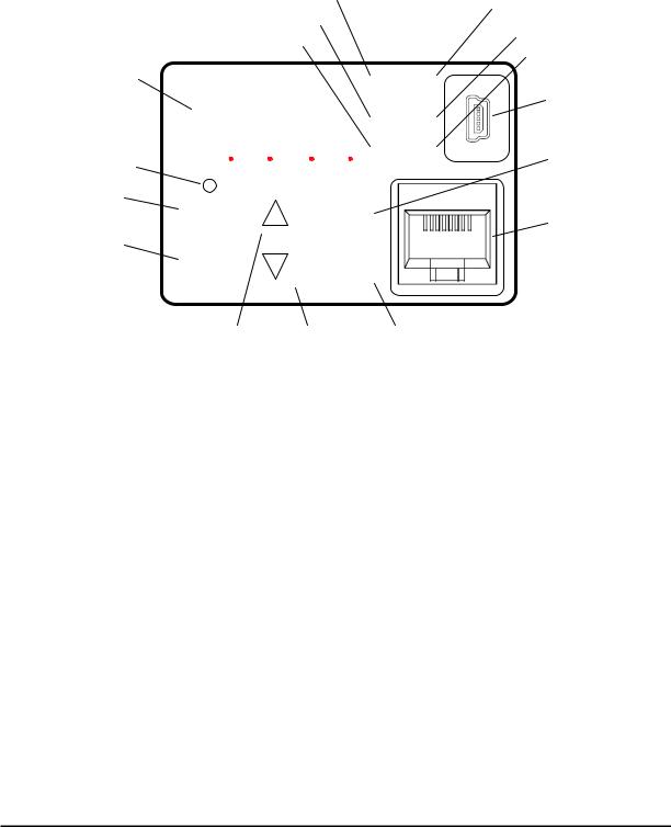
Using the Front Panel Keypad
Please take a moment to familiarize yourself with the keypad layout shown in the figure below. The display is used in programming the inverter’s parameters, as well as monitoring specific parameter values during operation.
|
(4) RUN LED |
(1) POWER LED |
|||||||||||
|
(5) Monitor LED [Hz] |
(2) ALARM LED |
|||||||||||
|
(6) Monitor LED [A] |
(3) Program LED |
|||||||||||
|
(8) 7-seg LED |
||||||||||||
|
RUN |
PWR |
(15) USB connector |
||||||||||
|
(7) Run command LED |
8888 |
|||||||||||
|
A |
PRG |
|||||||||||
|
Hz |
ALM |
|||||||||||
|
(9) RUN key |
(10) STOP/RESET key |
|||||||||||
|
RUN |
1 |
STOP |
(16) RJ45 connector |
|||||||||
|
RESET |
||||||||||||
|
(11) ESC key |
||||||||||||
|
ESC |
2 |
SET |
||||||||||
(12) Up key (13) Down key (14) SET key
Key and Indicator Legend
|
Items |
Contents |
||||
|
(1) |
POWER LED |
Turns ON (Green) while the inverter is powered up. |
|||
|
(2) ALARM LED |
Turns ON (Red) when the inverter trips. |
||||
|
(3) |
Program LED |
Turns ON (Green) when the display shows changeable parameter. |
|||
|
Blinks when there is a mismatch in setting. |
|||||
|
(4) |
RUN LED |
Turns ON (Green) when the inverter is driving the motor. |
|||
|
(5) |
Monitor LED [Hz] |
Turns ON (Green) when the displayed data is frequency related. |
|||
|
(6) |
Monitor LED [A] |
Turns ON (Green) when the displayed data is current related. |
|||
|
(7) |
Run command LED |
Turns ON (Green) when a Run command is set to the operator. (Run key is effective.) |
|||
|
(8) |
7-seg LED |
Shows each parameter, monitors etc. |
|||
|
(9) |
RUN key |
Makes inverter run. |
|||
|
(10) STOP/RESET key |
Makes inverter decelerates to a stop. |
||||
|
Reset the inverter when it is in trip situation |
|||||
|
Go to the top of next function group, when a function mode is shown |
|||||
|
(11) ESC key |
Cancel the setting and return to the function code, when a data is shown |
||||
|
Moves the cursor to a digit left, when it is in digit-to-digit setting mode |
|||||
|
Pressing for 1 second leads to display data of d001, regardless of current display. |
|||||
|
(12) Up key |
Increase or decrease the data. |
||||
|
(13) Down key |
Pressing the both keys at the same time gives you the digit-to-digit edit. |
||||
|
Go to the data display mode when a function code is shown |
|||||
|
(14) SET key |
Stores the data and go back to show the function code, when data is shown. |
||||
|
Moves the cursor to a digit right, when it is in digit-to-digit display mode |
|||||
|
(15) USB connector |
Connect USB connector (mini-B) for using PC communication |
||||
|
(16) RJ45 connector |
Connect RJ45 jack for remote operator |
14

Keys, Modes, and Parameters
The purpose of the keypad is to provide a way to change modes and parameters. The term function applies to both monitoring modes and parameters. These are all accessible through function codes that are primary 4-character codes. The various functions are separated into related groups identifiable by the left-most character, as the table shows.
RUN 
 PWR
PWR
8888
 Hz
Hz 
 ALM A PGM
|
RUN |
1 |
STOP |
|
|
RESET |
|||
ESC 
 2
2 
 SET
SET
|
Function |
Type (Category) of Function |
Mode to Access |
PRG LED |
||||||||
|
Group |
Indicator |
||||||||||
|
“d” |
Monitoring functions |
Monitor |
|||||||||
|
“F” |
Main profile parameters |
Program |
|||||||||
|
“A” |
Standard functions |
Program |
|||||||||
|
“b” |
Fine tuning functions |
Program |
|||||||||
|
“C” |
Intelligent terminal functions |
Program |
|||||||||
|
“H” |
Motor constant related functions |
Program |
|||||||||
|
“P” |
Pulse train input, torque, EzSQ, and |
Program |
|||||||||
|
communication related functions |
|||||||||||
|
“U” |
User selected parameters |
Program |
|||||||||
|
“E” |
Error codes |
− |
− |
You can see from the following page how to monitor and/or program the parameters.
Keypad Navigation Map
The WJ200 Series inverter drives have many programmable functions and parameters. Chapter 3 will cover these in detail, but you need to access just a few items to perform the powerup test. The menu structure makes use of function codes and parameter codes to allow programming and monitoring with only a 4-digit display and keys and LEDs. So, it is important to become familiar with the basic navigation map of parameters and functions in the diagram below. You may later use this map as a reference.
15
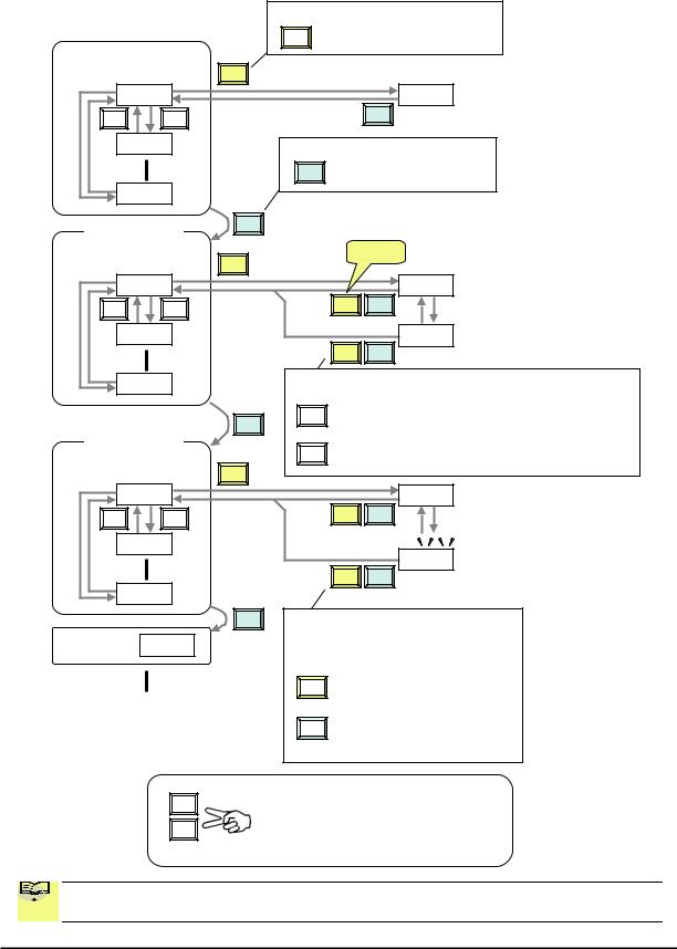
|
Func. code display |
|||
|
SET |
: Moves to data display |
||
|
Group «d» |
|||
|
Func. code display |
SET |
||||
|
d001 |
0.00 |
||||
|
V |
U |
ESC |
|||
|
d002 |
Func. code display |
||||
|
ESC : Jumps to the next group |
|||||
|
d104 |
|||||
|
Group «F» |
ESC |
||||
|
Func. code display |
SET |
Save |
|||
|
F001 |
50.00 |
||||
|
V |
U |
SET |
ESC |
||
|
F002 |
50.01 |
||||
|
SET |
ESC |
||||
|
F004 |
Data display |
(F001 to F003) |
|||
|
Data does not blink because of real time synchronizing |
|||||
|
ESC |
SET : Saves the data in EEPROM |
||||
|
and returns to func. code display. |
|||||
|
Group «A» |
|||||
|
ESC |
: Returns to func. code display without saving data. |
||||
|
Func. code display |
|||||
|
SET |
|||||
|
A001 |
00 |
||||
|
V |
U |
SET |
ESC |
||
|
A002 |
|||||
|
01 |
|||||
|
SET |
ESC |
||||
|
A165 |
ESC Data display
When data is changed, the display starts blinking, which means that new data has not been activated yet.
|
SET |
: Saves the data in EEPROM and |
|
returns to func. code display. |
|
|
: Cancels the data change and |
|
|
ESC |
|
|
returns to func. code display. |
Press the both up and down key at the same time in func. code or data display, then single-digit edit mode will be enabled.
Refer to 2-34 for further information.

 NOTE: Pressing the [ESC] key will make the display go to the top of next function group,
  regardless the display contents. (e.g. A021 [ESC] b001)
16
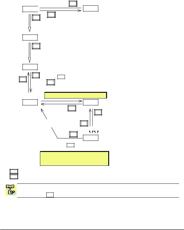
[Setting example]
After power ON, changing from 0.00 display to change the A002 (Run command source) data.
Press [ESC] key to show
the function code
ESC
d001 

SET
ESC
Data of d001 will be shown on the display after the first power ON
0.00
Press [ESC] key to move on to the function group F001
F001
ESC
Press [ESC] key Once to move on to the function group A001.
A001
U V 

Press Up key to change increase
|
function code (A001 |
A002) |
Press SET key to display the data of A002
SET
Display is solid lighting.
A002
ESC
Press up key to increase the data (02 01)
SET
Press SET key to set and save the data
When data is changed, the display starts blinking, which means that new data has not been activated yet.
SET :Fix and stores the data and moves back to the function code
ESC :Cancels the change and moves back to the function code
Function code dxxx are for monitor and not possible to change.
Function codes Fxxx other than F004 are reflected on the performance just after changing the data
(before pressing SET key), and there will be no blinking.
17

|
When a function code is shown… |
When a data is shown… |
||||||||||
|
Cancels the change and moves back to the |
|||||||||||
|
ESC |
key |
Move on to the next function group |
|||||||||
|
function code |
|||||||||||
|
Fix and stores the data and moves back to |
|||||||||||
|
SET |
key |
Move on to the data display |
|||||||||
|
the function code |
|||||||||||
|
key |
Increase function code |
Increase data value |
|||||||||
|
U |
|||||||||||
|
key |
Decrease function code |
Decrease data value |
|||||||||
|
V |
|||||||||||
Note
Keep pressing for more than 1 second leads to d001 display, regardless the display situation. But note that the display will circulates while keep pressing the [ESC] key because of the original function of the key.
(e.g. F001 A001 b001 C001 … displays 50.00 after 1 second)
18
![]()
Connecting to PLCs and Other Devices
Hitachi inverters (drives) are useful in many types of applications. During installation, the inverter keypad (or other programming device) will facilitate the initial configuration. After installation, the inverter will generally receive its control commands through the control logic connector or serial interface from another controlling device. In a simple application such as single-conveyor speed control, a Run/Stop switch and potentiometer will give the operator all the required control. In a sophisticated application, you may have a programmable logic controller (PLC) as the system controller, with several connections to the inverter.
It is not possible to cover all the possible types of application in this manual. It will be necessary for you to know the electrical characteristics of the devices you want to connect to the inverter. Then, this section and the following sections on I/O terminal functions can help you quickly and safely connect those devices to the inverter.
CAUTION: It is possible to damage the inverter or other devices if your application exceeds the maximum current or voltage characteristics of a connection point.
The connections between the inverter and other devices rely on the electrical input/output characteristics at both ends of each connection, shown in the diagram to the right. The inverter’s configurable inputs accept either a sourcing or sinking output from an external device (such as PLC). This chapter shows the inverter’s internal electrical component(s) at each I/O terminal. In some cases, you will need to insert a power source in the interface wiring.
In order to avoid equipment damage and get your application running smoothly, we recommend drawing a schematic of each connection between the inverter and the other device. Include the internal components of each device in the schematic, so that it makes a complete circuit loop.
After making the schematic, then:
1.Verify that the current and voltage for each connection is within the operating limits of each device.
|
Other device |
signal |
WJ200 inverter |
|
|
Input |
Output |
||
|
return |
|||
|
circuit |
circuit |
||
|
Output |
signal |
Input |
|
|
return |
|||
|
circuit |
circuit |
||
|
Other device |
WJ200 inverter |
||
|
P24 |
+ — 24V |
||
|
1 |
|||
|
2 |
Input |
||
|
… |
3 |
circuits |
|
|
… |
|||
|
7 |
|||
|
GND |
L |
2.Make sure that the logic sense (active high or active low) of any ON/OFF connection is correct.
3.Check the zero and span (curve end points) for analog connections, and be sure the scale factor from input to output is correct.
4.Understand what will happen at the system level if any particular device suddenly loses power, or powers up after other devices.
19
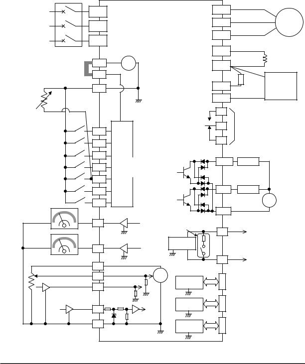
Example Wiring Diagram
The schematic diagram below provides a general example of logic connector wiring, in addition to basic power and motor wiring converted in Chapter 2. The goal of this chapter is to help you determine the proper connections for the various terminals shown below for your application needs.
|
Breaker, MCCB |
|||||||||
|
or GFI |
|||||||||
|
R |
WJ200 |
(T1) |
|||||||
|
Power source, |
U |
||||||||
|
(L1) |
|||||||||
|
3-phase or |
S |
V(T2) |
Motor |
||||||
|
1-phase, per |
|||||||||
|
inverter model |
(L2) |
W(T3) |
|||||||
|
T |
|||||||||
|
N(L3) |
PD/+1 |
||||||||
|
24V |
DC reactor |
||||||||
|
P24 |
+ — |
P/+ |
(optional) |
||||||
|
Jumper wire |
|||||||||
|
(Sink logic) |
PLC |
Braking |
|||||||
|
Brake |
|||||||||
|
unit (optional) |
|||||||||
|
L |
RB |
resistor |
|||||||
|
(optional) |
|||||||||
|
Thermistor |
Forward |
L |
N/- |
||||||
|
GND for logic inputs |
AL1 |
Relay contacts, |
|||||||
|
Intelligent inputs, |
AL0 |
type 1 Form C |
|||||||
|
7 terminals |
1 |
||||||||
|
NOTE: For the wiring |
|||||||||
|
AL2 |
|||||||||
|
of intelligent I/O and |
2 |
||||||||
|
analog inputs, be sure |
Input |
Open collector output |
|||||||
|
to use twisted pair / |
3/GS1 |
circuits |
Output circuit |
Freq. arrival signal |
|||||
|
shielded cable. Attach |
[5] configurable as |
11/EDM |
|||||||
|
the shielded wire for |
4/GS2 |
Load |
|||||||
|
each signal to its |
discrete input or |
||||||||
|
respective common |
5/PTC |
thermistor input |
|||||||
|
terminal at the inverter |
|||||||||
|
end only. |
12 |
Load |
|||||||
|
Input impedance of |
6 |
||||||||
|
each intelligent input is |
+ |
||||||||
|
4.7kΩ |
7/EB |
||||||||
|
Meter |
CM2 |
— |
|||||||
|
EO |
Termination resistor (200Ω) |
GND for logic outputs |
|||||||
|
(Change by slide switch) |
SP |
||||||||
|
Meter |
L |
Serial communication port |
|||||||
|
RS485 |
|||||||||
|
AM |
transceiver |
(RS485/Modbus) |
|||||||
|
L |
L |
SN |
NOTE: Common for |
||||||
|
Analog reference |
10Vdc |
||||||||
|
H |
RS485 is “L”. |
||||||||
|
0~10VDC |
|||||||||
|
O |
+ |
RS485 |
RJ45 port |
||||||
|
Apprx.10kΩ |
— |
||||||||
|
4~20mA |
(Optional operator port) |
||||||||
|
OI |
transceiver |
||||||||
|
Apprx.100Ω |
|||||||||
|
Pulse train input |
L |
USB (mini-B) port |
|||||||
|
L |
|||||||||
|
USB |
|||||||||
|
24Vdc 32kHz max. |
(PC communication port) |
||||||||
|
EA |
transceiver |
USB power: Self power |
|||||||
|
L |
|||||||||
|
L |
Option port |
Option port connector |
|||||||
|
GND for analog signals |
controller |
||||||||
|
L |
|||||||||
|
L |
|||||||||
20

Control Logic Signal Specifications
The control logic connectors are located just behind the front housing cover. The relay contacts are just to the left of the logic connectors. Connector labeling is shown below.
|
Relay |
SN 7 |
6 |
5 4 |
3 |
2 |
1 |
L |
PLC P24 |
|||
|
contacts |
Jumper wire |
||||||||||
|
SP |
EO |
EA |
H |
O |
OI |
L |
AM CM2 |
12 11 |
|||
|
AL2 AL1 AL0 |
|||||||||||
|
RS485 |
Pulse |
Pulse |
Analog |
Analog |
Logic |
||||||
|
comm. |
Train |
Train |
input |
output |
output |
||||||
|
output |
input |
||||||||||
|
Terminal Name |
Description |
Ratings |
|||||||||
|
P24 |
+24V for logic inputs |
24VDC, 100mA. (do not short to terminal L) |
|||||||||
|
PLC |
Intelligent input common |
To change to sink type, remove the jumper |
|||||||||
|
wire between [PLC] and [L], and connect it |
|||||||||||
|
between [P24] and [PLC]. In this case, |
|||||||||||
|
connecting [L] to [1]~[7] makes each input |
|||||||||||
|
ON. Please remove the jumper wire when |
|||||||||||
|
using external power supply. |
|||||||||||
|
1 |
Discrete logic inputs |
27VDC max. (use PLC or an external supply |
|||||||||
|
2 |
(Terminal [3],[4],[5] and [7] |
referenced to terminal L) |
|||||||||
|
3/GS1 |
have dual function. See |
||||||||||
|
4/GS2 |
following description and |
||||||||||
|
5/PTC |
related pages for the details.) |
||||||||||
|
6 |
|||||||||||
|
7/EB |
Functionality is based on ISO13849-1 |
||||||||||
|
GS1(3) |
Safe stop input GS1 |
||||||||||
|
GS2(4) |
Safe stop input GS2 |
See appendix for the details. |
|||||||||
|
PTC(5) |
Motor thermistor input |
Connect motor thermistor between PTC and |
|||||||||
|
L terminal to detect the motor temperature. |
|||||||||||
|
Set 19 in C005. |
|||||||||||
|
EB(7) |
Pulse train input B |
2kHz max. |
|||||||||
|
Common is [PLC] |
|||||||||||
|
EA |
Pulse train input A |
32kHz max. |
|||||||||
|
Common is [L] |
|||||||||||
|
L (in upper row) *1 |
GND for logic inputs |
Sum of input [1]~[7] currents (return) |
|||||||||
|
11/EDM |
Discrete logic outputs [11] |
50mA max. ON state current, |
|||||||||
|
(Terminal [11] has dual |
27 VDC max. OFF state voltage |
||||||||||
|
function. See following |
Common is CM2 |
||||||||||
|
description and related pages |
In case the EDM is selected, the functionality |
||||||||||
|
for the details.) |
is based on ISO13849-1 |
||||||||||
|
4VDC max. ON state voltage depression |
|||||||||||
|
12 |
Discrete logic outputs [12] |
50mA max. ON state current, |
|||||||||
|
27 VDC max. OFF state voltage |
|||||||||||
|
Common is CM2 |
|||||||||||
|
CM2 |
GND for logic output |
100 mA: [11], [12] current return |
|||||||||
|
AM |
Analog voltage output |
0~10VDC 2mA maximum |
|||||||||
|
EO |
Pulse train output |
10VDC 2mA maximum, 32kHz maximum |
|||||||||
|
L (in bottom row) *2 GND for analog signals |
Sum of [OI], [O], and [H] currents (return) |
||||||||||
|
OI |
Analog current input |
4 to 19.6 mA range, 20 mA nominal, |
|||||||||
|
input impedance 100 Ω |
|||||||||||
|
21 |
|
Terminal Name |
Description |
Ratings |
||||
|
O |
Analog voltage input |
0 to 9.8 VDC range, 10 VDC nominal, |
||||
|
input impedance 10 kΩ |
||||||
|
H |
+10V analog reference |
10VDC nominal, 10mA max. |
||||
|
SP, SN |
Serial communication terminal |
For RS485 Modbus communication. |
||||
|
AL0, AL1, AL2 *3 |
Relay common contact |
250VAC, |
2.5A |
(R load) max. |
||
|
250VAC, |
0.2A |
(I load, P.F.=0.4) max. |
||||
|
100VAC, |
10mA |
min. |
||||
|
30VDC, |
3.0A |
(R load) max. |
||||
|
30VDC, |
0.7A |
(I load, P.F.=0.4) max. |
||||
|
5VDC, 100mA |
min. |
|||||
|
Note 1: |
The two terminals [L] are electrically connected together inside the inverter. |
|||||
|
Note 2: We recommend using [L] logic GND (to the right) for logic input circuits and [L] |
||||||
|
analog GND (to the left) for analog I/O circuits. |
||||||
|
Note 3: |
Refer to page 39 for details of trip signals. |
Wiring sample of control logic terminal (sink logic)
|
Jumper wire |
||||||||||||||||||||||||||||||||
|
(sink logic) |
||||||||||||||||||||||||||||||||
|
SN |
7/EB |
6 |
5/PTC |
4/GS2 |
3/GS1 |
2 |
1 |
L |
PLC |
P24 |
||||||||||||||||||||||
|
SP |
EO |
EA |
H |
O |
OI |
L |
AM |
CM2 |
12 |
11/EDM |
||||||||||||||||||||||

 RY
RY  RY
RY
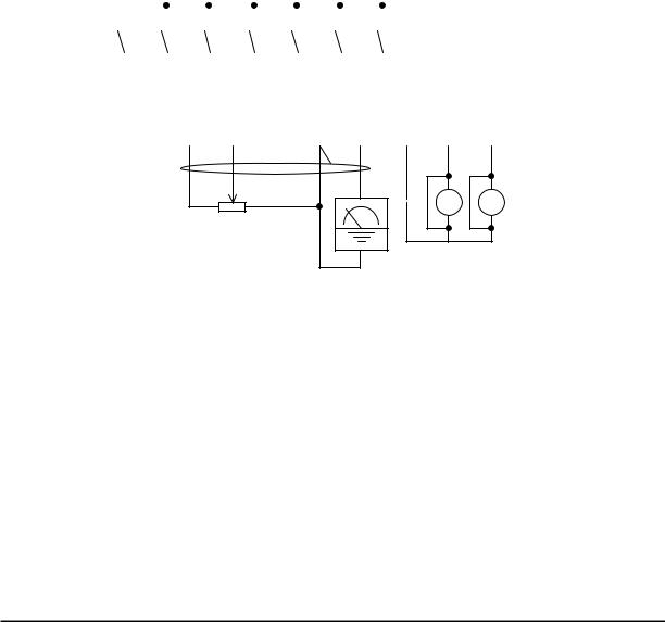
Variable resistor for freq. setting (1kΩ-2kΩ)
Freq. meter
Note: If relay is connected to intelligent output, install a diode across the relay coil (reverse-biased) in order to suppress the turn-off spike.
Caution for intelligent terminals setting
In turning on power when the input to the intelligent terminals become the following operations, the set data might be initialized.
Please ensure not becoming the following operations, in changing the function allocation of the intelligent input terminal.
1)Turning on power while [Intelligent input terminal 1/2/3 are ON] and [Intelligent input terminal 4/5/6/7 are OFF].
2)After 1)’s condition, turning off power.
3)After 2)’s condition, turning on power while [Intelligent input terminal 2/3/4 are ON] and [Intelligent input terminal 1/5/6/7 are OFF].
22
Sink/source logic of intelligent input terminals
|
Sink or source logic is switched by a jumper wire as below. |
||||||||||||||||||||||||||
|
Sink logic |
Source logic |
|||||||||||||||||||||||||
|
2 |
1 |
L |
PLC |
P24 |
2 |
1 |
L |
PLC |
P24 |
|||||||||||||||||
|
Jumper wire |
Jumper wire |
|||||||||||||||||||||||||
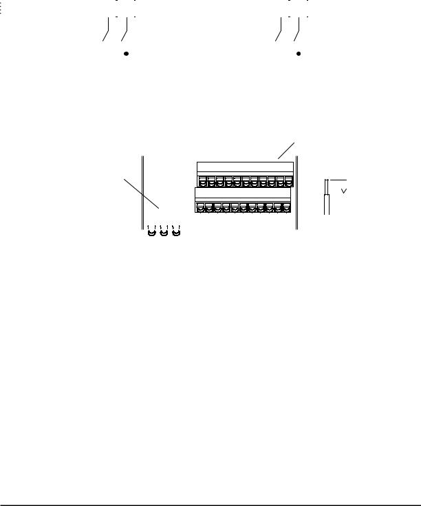
Wire size for control and relay terminals
Use wires within the specifications listed below. For safe wiring and reliability, it is recommended to use ferrules, but if solid or stranded wire is used, stripping length should be 8mm.
Control logic terminal
Relay output terminal
 8mm
8mm
|
Solid |
Stranded |
Ferrule |
|||||||||||||
|
mm2 (AWG) |
mm2 (AWG) |
mm2 (AWG) |
|||||||||||||
|
Control logic |
0.2 to 1.5 |
0.2 to 1.0 |
0.25 to 0.75 |
||||||||||||
|
terminal |
(AWG 24 to 16) |
(AWG 24 to 17) |
(AWG 24 to 18) |
||||||||||||
|
Relay terminal |
0.2 to 1.5 |
0.2 to 1.0 |
0.25 to 0.75 |
||||||||||||
|
(AWG 24 to 16) |
(AWG 24 to 17) |
(AWG 24 to 18) |
|||||||||||||
23

Recommended ferrule
For safe wiring and reliability, it is recommended to use following ferrules.
|
Wire size |
Model name of |
L [mm] |
Φd [mm] |
ΦD [mm] |
|
mm2 (AWG) |
ferrule * |
|||
|
0.25 (24) |
AI 0.25-8YE |
12.5 |
0.8 |
2.0 |
|
0.34 (22) |
AI 0.34-8TQ |
12.5 |
0.8 |
2.0 |
|
0.5 (20) |
AI 0.5-8WH |
14 |
1.1 |
2.5 |
|
0.75 (18) |
AI 0.75-8GY |
14 |
1.3 |
2.8 |
* Supplier: Phoenix contact
Crimping pliers: CRIPMFOX UD 6-4 or CRIMPFOX ZA 3
How to connect?
(1)Push down an orange actuating lever by a slotted screwdriver (width 2.5mm max.).
(2)Plug in the conductor.
(3)Pull out the screwdriver then the conductor is fixed.
2.5mm
|
Push down an |
Plug in the |
Pull out the |
|
orange actuating |
conductor. |
screwdriver to fix |
|
lever. |
the conductor. |
24

Intelligent Terminal Listing
Intelligent Inputs
Use the following table to locate pages for intelligent input material in this chapter.
Input Function Summary Table
|
Symbol |
Code |
Function Name |
Page |
||
|
FW |
00 |
Forward Run/Stop |
|||
|
RV |
01 |
Reverse Run/Stop |
|||
|
CF1 |
02 |
Multi-speed Select, Bit 0 (LSB) |
|||
|
CF2 |
03 |
Multi-speed Select, Bit 1 |
|||
|
CF3 |
04 |
Multi-speed Select, Bit 2 |
|||
|
CF4 |
05 |
Multi-speed Select, Bit 3 (MSB) |
|||
|
JG |
06 |
Jogging |
|||
|
DB |
07 |
External DC braking |
|||
|
SET |
08 |
Set (select) 2nd Motor Data |
|||
|
2CH |
09 |
2-stage Acceleration and Deceleration |
|||
|
FRS |
11 |
Free-run Stop |
|||
|
EXT |
12 |
External Trip |
|||
|
USP |
13 |
Unattended Start Protection |
|||
|
CS |
14 |
Commercial power source switchover |
|||
|
SFT |
15 |
Software Lock |
|||
|
AT |
16 |
Analog Input Voltage/Current Select |
|||
|
RS |
18 |
Reset Inverter |
|||
|
PTC |
19 |
PTC thermistor Thermal Protection |
|||
|
STA |
20 |
Start (3-wire interface) |
|||
|
STP |
21 |
Stop (3-wire interface) |
|||
|
F/R |
22 |
FWD, REV (3-wire interface) |
|||
|
PID |
23 |
PID Disable |
|||
|
PIDC |
24 |
PID Reset |
|||
|
UP |
27 |
Remote Control UP Function |
|||
|
DWN |
28 |
Remote Control Down Function |
|||
|
UDC |
29 |
Remote Control Data Clearing |
|||
|
OPE |
31 |
Operator Control |
|||
|
SF1~SF7 |
32~38 |
Multi-speed Select,Bit operation Bit 1~7 |
|||
|
OLR |
39 |
Overload Restriction Source Changeover |
|||
|
TL |
40 |
Torque Limit Selection |
|||
|
TRQ1 |
41 |
Torque limit switch 1 |
|||
|
TRQ2 |
42 |
Torque limit switch 2 |
|||
|
BOK |
44 |
Brake confirmation |
|||
|
LAC |
46 |
LAD cancellation |
|||
|
PCLR |
47 |
Pulse counter clear |
|||
|
ADD |
50 |
ADD frequency enable |
|||
|
F-TM |
51 |
Force Terminal Mode |
|||
|
ATR |
52 |
Permission for torque command input |
|||
|
KHC |
53 |
Clear watt-hour data |
|||
|
MI1~MI7 |
56~62 |
General purpose input (1)~(7) |
|||
|
AHD |
65 |
Analog command hold |
|||
|
CP1~CP3 |
66~68 |
Multistage-position switch (1)~(3) |
|||
|
ORL |
69 |
Limit signal of zero-return |
|||
|
ORG |
70 |
Trigger signal of zero-return |
|||
|
SPD |
73 |
Speed/position changeover |
|||
|
GS1 |
77 |
STO1 input (Safety related signal) |
|||
|
GS2 |
78 |
STO2 input (Safety related signal) |
|||
|
485 |
81 |
Starting communication signal |
|||
|
PRG |
82 |
Executing EzSQ program |
|||
|
HLD |
83 |
Retain output frequency |
|||
|
ROK |
84 |
Permission of Run command |
|||
|
EB |
85 |
Rotation direction detection (phase B) |
25

Use the following table to locate pages for intelligent input material in this chapter.
Input Function Summary Table
|
Symbol |
Code |
Function Name |
Page |
||
|
DISP |
86 |
Display limitation |
|||
|
NO |
255 |
No assign |
Intelligent Outputs
Use the following table to locate pages for intelligent output material in this chapter.
Input Function Summary Table
|
Symbol |
Code |
Function Name |
Page |
||
|
RUN |
00 |
Run Signal |
|||
|
FA1 |
01 |
Frequency Arrival Type 1–Constant Speed |
|||
|
FA2 |
02 |
Frequency Arrival Type 2–Over frequency |
|||
|
OL |
03 |
Overload Advance Notice Signal |
|||
|
OD |
04 |
PID Deviation error signal |
|||
|
AL |
05 |
Alarm Signal |
|||
|
FA3 |
06 |
Frequency Arrival Type 3–Set frequency |
|||
|
OTQ |
07 |
Over/under Torque Threshold |
|||
|
UV |
09 |
Undervoltage |
|||
|
TRQ |
10 |
Torque Limited Signal |
|||
|
RNT |
11 |
Run Time Expired |
|||
|
ONT |
12 |
Power ON time Expired |
|||
|
THM |
13 |
Thermal Warning |
|||
|
BRK |
19 |
Brake Release Signal |
|||
|
BER |
20 |
Brake Error Signal |
|||
|
ZS |
21 |
Zero Hz Speed Detection Signal |
|||
|
DSE |
22 |
Speed Deviation Excessive |
|||
|
POK |
23 |
Positioning Completion |
|||
|
FA4 |
24 |
Frequency Arrival Type 4–Over frequency |
|||
|
FA5 |
25 |
Frequency Arrival Type 5–Set frequency |
|||
|
OL2 |
26 |
Overload Advance Notice Signal 2 |
|||
|
ODc |
27 |
Analog Voltage Input Disconnect Detection |
|||
|
OIDc |
28 |
Analog Voltage Output Disconnect Detection |
|||
|
FBV |
31 |
PID Second Stage Output |
|||
|
NDc |
32 |
Network Disconnect Detection |
|||
|
LOG1~3 |
33~35 |
Logic Output Function 1~3 |
|||
|
WAC |
39 |
Capacitor Life Warning Signal |
|||
|
WAF |
40 |
Cooling Fan Warning Signal |
|||
|
FR |
41 |
Starting Contact Signal |
|||
|
OHF |
42 |
Heat Sink Overheat Warning |
|||
|
LOC |
43 |
Low load detection |
|||
|
MO1~3 |
44~46 |
General Output 1~3 |
|||
|
IRDY |
50 |
Inverter Ready Signal |
|||
|
FWR |
51 |
Forward Operation |
|||
|
RVR |
52 |
Reverse Operation |
|||
|
MJA |
53 |
Major Failure Signal |
|||
|
WCO |
54 |
Window Comparator for Analog Voltage Input |
|||
|
WCOI |
55 |
Window Comparator for Analog Current Input |
|||
|
FREF |
58 |
Frequency Command Source |
|||
|
REF |
59 |
Run Command Source |
|||
|
SETM |
60 |
2nd Motor in operation |
|||
|
EDM |
62 |
STO (Safe Torque Off) Performance Monitor |
|||
|
(Output terminal 11 only) |
|||||
|
OP |
63 |
Option control signal |
|||
|
no |
255 |
Not used |
26
Using Intelligent Input Terminals
Terminals [1], [2], [3], [4], [5], [6] and [7] are identical, programmable inputs for general use. The input circuits can use the inverter’s internal (isolated) +24V field supply or an external power supply. This section describes input circuits operation and how to connect them properly to switches or transistor outputs on field devices.
The WJ200 inverter features selectable sinking or sourcing inputs. These terms refer to the connection to the external switching device–it either sinks current (from the input to GND) or sources current (from a power source) into the input. Note that the sink/source naming convention may be different in your particular country or industry. In any case, just follow the wiring diagrams in this section for your application.
The inverter has a jumper wire for configuring the choice of sinking or sourcing inputs. To access it, you must remove the front cover of the inverter housing. In the figure to the top right, the jumper wire is shown as attached to the logic terminal block (connector). If you need to change to the source type connection, remove the jumper wire and connect it as shown in the figure at the bottom right.
Logic inputs
7 6 5 4 3 2 1 L PLC P24
Jumper wire 
Sink logic connection
7 6  5 4 3 2 1 L PLC P24
Jumper wire 
Source logic connection
CAUTION: Be sure to turn OFF power to the inverter before changing the jumper wire position. Otherwise, damage to the inverter circuitry may occur.
[PLC] Terminal Wiring – The [PLC] terminal (Programmable Logic Control terminal) is named to include various devices that can connect to the inverter’s logic inputs. In the figure to the right, note the [PLC] terminal and the jumper wire. Locating the jumper wire between [PLC] and [L] sets the input logic source type, which is the default setting for EU and US versions. In this case, you connect input terminal to [P24] to make it active. If instead you locate the jumper wire between [PLC] and [P24], the input logic will be sink type. In this case, you connect the input terminal to [L] to make it active.
Jumper wire
|
for sink logic |
WJ200 inverter |
|||||||||||
|
P24 |
||||||||||||
|
Input common |
24V |
|||||||||||
|
PLC |
||||||||||||
|
+ |
||||||||||||
|
— |
||||||||||||
1
Input circuits
7
Logic GND
L
Jumper wire for source logic
The wiring diagram on the following pages show the four combinations of using sourcing or sinking inputs, and using the internal or an external DC supply.
27
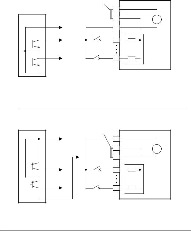
The two diagrams below input wiring circuits using the inverter’s internal +24V supply. Each diagram shows the connection for simple switches, or for a field device with transistor outputs. Note that in the lower diagram, it is necessary to connect terminal [L] only when using the field device with transistors. Be sure to use the correct connection of the jumper wire shown for each wiring diagram.
Sinking Inputs, Internal Supply
Jumper wire = [PLC] – [P24] position
Open collector outputs,
NPN transistors
|
Jumper wire |
WJ200 |
||
|
P24 |
24V |
||
|
Input common |
|||
|
PLC |
+ |
||
|
Logic GND |
— |
||
|
L |
|||
|
1 |
|||
|
Input |
|||
|
circuits |
|||
|
7 |
|||
|
Input switches |
Sourcing Inputs, Internal Supply
|
Jumper wire = [PLC] – [L] position |
||
|
Field device |
Common to |
|
|
[P24] |
||
|
1 |
||
|
7 |
||
|
to PNP bias |
GND |
|
|
circuits |
||
PNP transistor sousing outputs
|
Jumper wire |
WJ200 |
|
|
P24 |
24V |
|
|
Input common |
||
|
PLC |
+ |
|
|
— |
||
|
L |
||
|
Logic GND |
||
|
1 |
||
|
Input |
||
|
circuits |
||
|
7 |
||
|
Input switches |
28
 Loading…
перейти к содержанию
![]() 0Вдохновляйте на будущее
0Вдохновляйте на будущее

WJ200
Быстрое начало
Быстрый старт: главное
параметры
b037 — разблокирует параметры (по умолчанию 04)
A001 — Источник частоты (скорости) (по умолчанию 02)
A002 — Источник команды запуска (по умолчанию 02)
b012 — Ток паспортной таблички двигателя (по умолчанию варьируется)
b091 — режим остановки (по умолчанию 00)
H004 — Количество полюсов на паспортной табличке двигателя (по умолчанию 4 полюса)
F001 – Настройка скорости клавиатуры (по умолчанию 00.00)
F002 — время разгона (по умолчанию 10 секунд)
F003 — время торможения (по умолчанию 10 секунд)
Чтобы разблокировать все параметры

- Нажмите ESC, чтобы войти в режим программирования
- Нажимайте ESC до тех пор, пока параметр b001 не появится на дисплее вашего привода.
- Нажимайте клавишу ВВЕРХ, пока не будет достигнуто значение b037.
- Затем нажмите кнопку SET, чтобы ввести параметр b037.
- Теперь вы можете изменить 04 на 00 с помощью клавиши вниз
- Нажмите кнопку SET, чтобы сохранить данные Теперь вы развязали свой привод WJ200!
Установка тока двигателя

- Нажмите ESC, чтобы войти в режим программирования
- Нажимайте ESC до тех пор, пока параметр b001 не появится на дисплее вашего привода.
- Нажимайте клавишу ВВЕРХ, пока не будет достигнуто значение b012.
- Затем нажмите кнопку SET, чтобы ввести параметр b012.
- Теперь вы можете установить ток паспортной таблички двигателя с помощью клавиш «Вверх» и «Вниз».
- Нажмите кнопку SET, чтобы сохранить данные
Установка полюсов двигателя
 Нажмите ESC, чтобы войти в режим программирования
- Нажимайте ESC до тех пор, пока параметр H001 не появится на дисплее вашего привода.
- Нажимайте клавишу ВВЕРХ, пока не будет достигнуто значение H004.
- Затем нажмите кнопку SET, чтобы ввести параметр H004.
- Теперь вы можете установить полюса двигателя в зависимости от скорости вашего двигателя.
- Нажмите кнопку SET, чтобы сохранить данные
Число полюсов двигателя = 120*60/синхронная скорость (1200, 1800, 3600 об/мин)
 Нажмите ESC, чтобы войти в режим программирования
Установка эталона скорости

- Нажмите ESC, чтобы войти в режим программирования
- Нажимайте ESC до тех пор, пока параметр A001 не появится на дисплее вашего привода.
- Затем нажмите кнопку SET, чтобы ввести параметр A001.
- Выберите задание скорости из приведенных ниже вариантов.
00- Для использования потенциометра клавиатуры
01- Аналоговый вход (0-10 В постоянного тока или 4-20 мА) с клемм
02- При использовании клавиатуры установите скорость с помощью параметра F001.
03- При установке скорости через коммуникационную сеть Modbus
04- Дополнительная карта, используемая для скорости
06- Если ваше приложение использует вход импульсной последовательности
07- При установке скорости с помощью программирования Easy Sequence
10- Когда скорость является результатом операции, используемой в программировании вашего привода. - Нажмите кнопку SET, чтобы сохранить данные
Установка источника команды запуска

- Нажмите ESC, чтобы войти в режим программирования
- Нажимайте ESC до тех пор, пока параметр A001 не появится на дисплее вашего привода.
- Нажимайте клавишу ВВЕРХ, пока не будет достигнуто значение A002.
- Затем нажмите кнопку SET, чтобы ввести параметр A002.
- Теперь вы можете выбрать источник команды запуска из вариантов ниже.
01- Для использования цифрового входа через клеммы
02- Когда ваше приложение требует использования клавиатуры для запуска команды
03- Используйте эту опцию, когда запускаете привод через коммуникационную сеть Modbus.
04- Дополнительная карта, используемая для запуска - Нажмите кнопку SET, чтобы сохранить данные
Установка частоты или скорости

- Нажмите ESC, чтобы войти в режим программирования
- Нажимайте ESC до тех пор, пока параметр F001 не появится на дисплее вашего привода.
- Затем нажмите кнопку SET, чтобы ввести параметр F001.
- Теперь вы можете регулировать скорость вашего диска в зависимости от вашего приложения.
- Нажмите кнопку SET, чтобы сохранить данные
Параметр F001 можно настроить при остановленном или работающем драйвере.
Установка времени ускорения

- Нажмите ESC, чтобы войти в режим программирования
- Нажимайте ESC до тех пор, пока параметр F001 не появится на дисплее вашего привода.
- Нажимайте клавишу ВВЕРХ, пока не будет достигнута F002.
- Затем нажмите кнопку SET, чтобы ввести параметр F002.
- Теперь вы можете настроить время разгона вашего привода в зависимости от вашего приложения. Время регулируется клавишами вверх и вниз.
- Наконец, нажмите кнопку SET, чтобы сохранить данные
Установка времени торможения

- Нажмите ESC, чтобы войти в режим программирования
- Нажимайте ESC до тех пор, пока параметр F001 не появится на дисплее вашего привода.
- Нажимайте клавишу «Вверх», пока не будет достигнута F003.
- Затем нажмите кнопку SET, чтобы ввести параметр F003.
- Теперь вы можете настроить время торможения вашего привода в зависимости от вашего приложения. Время регулируется клавишами ВВЕРХ и ВНИЗ
- Нажмите кнопку SET, чтобы сохранить данные
Установка режима остановки

- Нажмите ESC, чтобы войти в режим программирования
- Нажимайте ESC до тех пор, пока параметр b001 не появится на дисплее вашего привода.
- Нажмите и удерживайте кнопку ВВЕРХ, пока не будет достигнуто значение b091.
- Затем нажмите кнопку SET, чтобы ввести параметр b091.
- Теперь вы можете выбрать режим остановки из вариантов ниже.
00- замедление до остановки (управляемая остановка)
01- остановка свободного хода (выбег) - Нажмите кнопку SET, чтобы сохранить данные
ТЕХНИЧЕСКАЯ ПОДДЕРЖКА
980-500-7141
WEBСАЙТ
https://www.hitachi-iesa.com/ac-drivesinverters
ЭЛ. АДРЕС
инвертор.Info@hitachi-iesa.com
Документы / Ресурсы
Hitachi WJ200 DC Drives PDF User Guides and Manuals for Free Download: Found (1) Manuals for Hitachi WJ200 Device Model (Quick Start Manual)
More DC Drives Device Models:
-
Applied Motion Products
3540 MO
Flip OverTypical wiring for Oscillator Mode using external speed Control pot Speed Control from a 0 to 5 Volt Analog Signal In oscillator mode, the 3540MO can rotate the motor a speed proportional to ananalog voltage. The voltage must be applied to the WPR terminal. The direction ofrotation will be controlled by the di …
3540 MO DC Drives, 2
-
BENSHAW
RSi GM2 Series
RSi GM2 SeriesVariable Frequency Drive1.0 to 15HP — 230V1.0 to 15HP — 460VInstruction Manual890054-00-00© 2020 Benshaw Inc.Benshaw retains the right to change specifications and illustrations in text without prior notification. The contents of this document maynot be copied without the explicit permission of Benshaw. …
RSi GM2 Series DC Drives, 282
-
YASKAWA
PROFINET V1000
Document Revision: v1.0.5of1 10page18805 Adams Ct., #110 ~ Morgan Hill, CA 95037, USA ~ +1-408.924.0808 ~ www.washlinksystems.com ~ suppo[email protected] GuideYaskawaV1000Basic User Guide …
PROFINET V1000 DC Drives, 10
-
YASKAWA
CIMR-VC series
YASKAWA Europe TOEP C710606 15C YASKAWA AC Drive — V1000 Quick Start Guide EN iENGLISHQuick Start GuideYASKAWA AC Drive V1000Compact Vector Control DriveModels: 200 V Class, Three-Phase Input: 0.1 to 18.5 kW200 V Class, Single-Phase Input: 0.1 to 4.0 kW400 V Class, Three-Phase Input: 0.2 to 18.5 kWMANUAL NO. TOEP …
CIMR-VC series Controller, 44
Recommended Documentation:
3.0
Rated 3 out of 5
3 out of 5 stars (based on 1 review)
Your overall rating
HITACHI WJ200 (01) PDF MANUAL
Click here to download HITACHI WJ200 (01) PDF MANUAL
HITACHI WJ200 (01) PDF MANUAL
FREE ENGLISH PDF
OPERATING INSTRUCTIONS
USER GUIDE – USER MANUAL
OWNER GUIDE – OWNER MANUAL
REFERENCE GUIDE – REFERENCE MANUAL
INSTRUCTION GUIDE – INSTRUCTION MANUAL
Your overall rating
- YouTube
HITACHI WJ200 (01) PDF MANUAL
HITACHI WJ200 (01) PDF MANUAL