Предложите, как улучшить StudyLib
(Для жалоб на нарушения авторских прав, используйте
другую форму
)
Ваш е-мэйл
Заполните, если хотите получить ответ
Оцените наш проект
1
2
3
4
5
- Manuals
- Brands
- Haas Manuals
- Power Tool
- UMC-750
- Operator’s manual
-
Contents
-
Table of Contents
-
Bookmarks
Quick Links
,
UMC-750
Operator’s Manual Supplement
96-8250
Revision G
December 2017
English
Original Instructions
Haas Automation Inc.
2800 Sturgis Road
Oxnard, CA 93030-8933
U.S.A. | HaasCNC.com
©
2017 Haas Automation, Inc. All Rights Reserved. Copy by Permission Only. Copyright Strictly Enforced.
Related Manuals for Haas UMC-750
Summary of Contents for Haas UMC-750
-
Page 1
UMC-750 Operator’s Manual Supplement 96-8250 Revision G December 2017 English Original Instructions Haas Automation Inc. 2800 Sturgis Road Oxnard, CA 93030-8933 U.S.A. | HaasCNC.com © 2017 Haas Automation, Inc. All Rights Reserved. Copy by Permission Only. Copyright Strictly Enforced. -
Page 3
Haas Automation, Inc. No patent liability is assumed with respect to the use of the information contained herein. Moreover, because Haas Automation strives constantly to improve its high-quality products, the information contained in this manual is subject to change without notice. -
Page 4
This product uses Java Technology from Oracle Corporation and we request that you acknowledge that Oracle owns the Java Trademark and all Java related Trademarks and agree to comply with the trademark guidelines at www.oracle.com/us/legal/third-party-trademarks/index.html. Any further distribution of the Java programs (beyond this appliance/machine) is subject to a legally binding End User License Agreement with Oracle. -
Page 5
Repair or Replacement Only Manufacturer’s sole liability, and Customer’s exclusive remedy under this warranty, with respect to any and all Haas products, shall be limited to repairing or replacing, at the discretion of the Manufacturer, the defective Haas product. Disclaimer of Warranty This warranty is Manufacturer’s sole and exclusive warranty, and is in lieu of all other… -
Page 6
Haas Product by any person, and Manufacturer shall not incur any liability to any person for any failure in design, production, operation, performance, or otherwise of any Haas Product, other than repair or replacement of same as set forth in the warranty above. -
Page 7
Manufacturer or its Authorized Representative. Customer realizes and acknowledges that the price of the Haas Products would be higher if Manufacturer were required to be responsible for damages and claims beyond the scope of this warranty. -
Page 8
Customer Advocate. You can find an electronic copy of this manual and other useful information on our website in the “Resource Center”. Join Haas owners online and be a part of the greater CNC community at these sites: diy.haascnc.com… -
Page 9
Once you contact the Haas Automation Customer Service Center, we will make every effort to work directly with you and your HFO to quickly resolve your concerns. At Haas Automation, we know that a good Customer-Distributor-Manufacturer relationship will help ensure continued success for all concerned. -
Page 10
viii… -
Page 11
Declaration of Conformity Product: Mill (Vertical and Horizontal)* *Including all options factory- or field-installed by a certified Haas Factory Outlet (HFO) Manufactured By: Haas Automation, Inc. 2800 Sturgis Road, Oxnard, CA 93030 805-278-1800 We declare, in sole responsibility, that the above-listed products, to which this declaration refers, comply with the regulations as outlined in the CE directive for Machining Centers: •… -
Page 12
USA: Haas Automation certifies this machine to be in compliance with the OSHA and ANSI design and manufacturing standards listed below. Operation of this machine will be compliant with the below-listed standards only as long as the owner and operator continue to follow the operation, maintenance, and training requirements of these standards. -
Page 13
How to Use This Manual To get the maximum benefit of your new Haas machine, read this manual thoroughly and refer to it often. The content of this manual is also available on your machine control under the HELP function. -
Page 14
Text Conventions Used in this Manual Description Text Example G00 G90 G54 X0. Y0.; Code Block text gives program examples. [CYCLE START] A Control Button Reference gives the name of a Press control key or button that you are to press. A File Path describes a sequence of file system Service >… -
Page 15: Table Of Contents
Overview……. . . 17 UMC-750 Workstations ……17 Axis Definitions .
-
Page 16
Introduction ……. 51 UMC-750 Maintenance Schedule ….51 More Information Online . -
Page 17: Chapter 1 Safety
Cutting tools, workholding, workpiece and coolant are beyond the scope and control of Haas Automation, Inc. Each of these potential hazards associated with it (sharp edges, heavy lifting considerations, chemical composition, etc) and it is the responsibility of the user to take appropriate action (PPE, training, etc).
-
Page 18: Summary Of Types Of Operation For Haas Automation Machine Tools
Summary of Types of Operation for Haas Automation Machine Tools Haas CNC Mills are intended for cutting and shaping of metals and other hard materials. They are general purpose in nature and a list of all of those materials and types of cutting would never be complete.
-
Page 19
Machine moving, unpacking, and installation • Haas machines are shipped to a user’s location almost ready to operate. They still require a trained service person to complete the installation. Installation and service instructions are provided separately from the Operator’s Manual. -
Page 20: Read Before Operating
• Do not reset a circuit breaker until the reason for the fault is investigated and understood. Only Haas-trained service personnel should troubleshoot and repair Haas equipment. • Do not press [POWER UP] on the control pendant before the machine is fully…
-
Page 21
Of the Automatic Tool Changer/tool and spindle — Press [RECOVER] and follow the on-screen instructions. • If the alarms do not reset or you are unable to clear a blockage, contact your Haas Factory Outlet (HFO) for assistance. Follow these guidelines when you work with the machine: •… -
Page 22
General Safety Notes Periodic maintenance of machine safety features: • Inspect door interlock mechanism for proper fit and function. • Inspect safety windows and enclosure for damage or leaks. • Verify all enclosure panels are in place. Door Safety Interlock maintenance: •… -
Page 23: Machine Environmental Limits
NOTE: Actual noise levels while cutting material are greatly affected by the user’s choice of material, cutting tools, speeds and feeds, workholding and other factors. These factors are application specific and are controlled by the user, not Haas Automation Inc.
-
Page 24: Unattended Operation
Setup Mode All Haas CNC machines are equipped with locks on the operator doors and a key switch on the side of the control pendant to lock and unlock setup mode. Generally, setup mode status (locked or unlocked) affects how the machine operates when the doors are opened.
-
Page 25
Safety 1.3.1 Machine Behavior with the Door Open For safety, machine operations stop when the door is open and the setup keyswitch is locked. The unlocked position allows limited machine functions with the door open. T1.2: Setup / Run Mode Limited Overrides with the Machine Doors Open Machine Function Keyswitch Locked Keyswitch Unlocked… -
Page 26: Robot Cells
Haas Automation, Inc. is not responsible for damage caused by modifications you make to your Haas machine(s) with parts or kits not manufactured or sold by Haas Automation, Inc. The use of such parts or kits may void your warranty.
-
Page 27: Safety Decals
Ask your HFO or your coolant dealer if you have questions about the specific coolant that you plan to use. The Haas Resource Center website has videos and other general information about coolant use and maintenance. You can also scan the code below with your mobile device to directly access this information.
-
Page 28: Decal Symbols Reference
Safety Decals • Green Circle — Describes a recommended action. • Black Circle — Gives information about machine or accessory operation. F1.1: Example Safety Decal Symbols: [1] Hazard Description, [2] Prohibited Action, [3] Recommended Action. 1.6.1 Decal Symbols Reference This section gives explanations and clarifications for the safety symbols you will see on your machine.
-
Page 29
Safety Symbol Description The Regen is used by the spindle drive to dissipate excess power and will get hot. Always use care around the Regen. There are high voltage components on the machine that can cause electrical shock. Always use care around high voltage components. Long tools are dangerous, especially at spindle speeds higher than 5000 RPM. -
Page 30
Safety Decals T1.4: Prohibited Action Symbols – Red Circles with Slash-Through Symbol Description Do not enter the machine enclosure when the machine is capable of automatic motion. When you must enter the enclosure to complete tasks, press [EMERGENCY STOP] or power off the machine. Put a safety tag on the control pendant to alert other people that you are inside the machine, and that they must not turn on or operate the machine. -
Page 31
Safety T1.5: Recommended Action Symbols – Green Circles Symbol Description Keep the machine doors closed. Always wear safety glasses or goggles when you are near a machine. Airborne debris can cause eye damage. Always wear hearing protection when you are near a machine. Machine noise can exceed 70 dBA. -
Page 32: Other Safety Information
You may find other decals on your machine, depending on the model and options installed. Be sure to read and understand these decals. These are examples of other safety decals in English. You can contact your Haas Factory Outlet (HFO) to get these decals in other languages.
-
Page 33: Chapter 2 Introduction
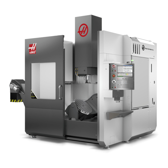
You can find specific details about the UMC family, including information that is beyond the scope of this document, at www.HaasCNC.com. UMC-750 Workstations F2.1: This diagram illustrates the UMC-750 three operator zones. • A: Operator Station. • B: Check and Maintain Lubricants.
-
Page 34: Axis Definitions
Axis Definitions Axis Definitions F2.2: This diagram illustrates the (5) axes available on the UMC-750 / UMC-750SS. -35° +110°…
-
Page 35
Introduction F2.3: This diagram illustrates the (5) axes available on the UMC-750P. + 45° — 45°… -
Page 36: Umc-750 Specifications
Spindle Nose to Table (~ min.) 4″ 102 mm Spindle Nose to Table (~ max.) 24″ 610 mm For detailed machine dimensions, including work envelope information, refer to the UMC-750 Machine Layout Drawing on www.haascnc.com. Table Width 19.7″ 500 mm Length 24.8″…
-
Page 37: Umc-750P Specifications
Introduction T2.2: General Requirements General Requirements Air Required 4 scfm, 100 psi 113 L/min, 6.9 bar Coolant Capacity 75 gal 284 L Power Requirement, Low Voltage 195-260 VAC / 100A Power Requirement, High Voltage 354-488 VAC / 50A Machine Weight 18,000 lb 8165 kg T2.3:…
-
Page 38
UMC-750P Specifications Travels S.A.E Metric Spindle Nose to Table (min.) 5″ 127 mm For detailed machine dimensions, including work envelope information, refer to the UMC-750 Machine Layout Drawing on www.haascnc.com. Table Width 14.75″ 375 mm Length 33″ 838 mm T-Slot Width 5/8″… -
Page 39
Introduction T2.6: Standard Features Standard Features Tool Center Point Control (TCPC), Dynamic Work Offsets (DWO), Remote Jog Handle*, Second Home*, Macros*, Spindle Orientation (SO)*, Coordinate Rotation and Scaling (COORD)*, TSC-Ready, Wireless Intuitive Probing System (WIPS) *Refer to the Mill Operator’s Manual (96-8210) for information on these features. -
Page 40
UMC-750P Specifications… -
Page 41: Chapter 3 Integrated Coolant Tank
Integrated Coolant Tank Chapter 3: Integrated Coolant Tank Introduction The UMC-750 coolant tank is integrated into the machine base. F3.1: UMC -750 Integrated Coolant Tank…
-
Page 42: Coolant Pump Location
The coolant pumps are on the tool changer side of the machine, behind the chip conveyor. The standard coolant box filter is mounted below the standard coolant pump. F3.2: UMC-750 Coolant Pump Location: [1] Chip Tray, [2] Gate Filter, [3] Coolant Box Filter, [4] Standard Coolant Pump, [5] TSC Coolant Pump Coolant Tank Clean-Out To clean out the coolant tank: Remove the coolant pumps.
-
Page 43
Integrated Coolant Tank F3.3: Coolant Tank Access Panels Add coolant to the tank and install the gate filter, coolant box filter, chip tray, and coolant pumps. Install the coolant tank access panels if you removed them. -
Page 44
Coolant Tank Clean-Out… -
Page 45: Chapter 4 Wireless Intuitive Probing System (Wips)
Refer to page 5 for more information on this process. Normally, you use WIPS to set tool and work offsets, but the UMC-750 includes a master gauge length tool in case you need to set offsets manually (if, for example, a probe stylus breaks or the batteries lose power).
-
Page 46: Machine Rotary Zero Point (Mrzp) Offsets
The Machine Rotary Zero Point (MRZP) Offsets are set at the factory. 4.3.1 Check MRZP Offsets with VPS The MRZP offsets can change over time. To make sure the UMC-750, UMC-750SS MRZP Offsets are correct do the following: Place the tooling ball in the center of the X axis.
-
Page 47
Wireless Intuitive Probing System (WIPS) F4.1: Calibration Tooling Ball Place the work probe in the spindle. Position the work probe over the tooling ball. Navigate to [EDIT]>VPS>PROBING>CALIBRATION>MRZP and select B-Axis Tilt C-Axis Rotary Finish Set and press [ENTER]. Type gage ball diameter and press [ENTER]. Follow the prompts to generate the probe program. -
Page 48
Machine Rotary Zero Point (MRZP) Offsets… -
Page 49: Chapter 5 G234 — Tool Center Point Control (Tcpc)
Like any other work setup, the workpiece must have a work offset applied to it. This tells the Haas CNC control where the workpiece is located on the machine table.
-
Page 50
G234 (TCPC) Off and the B and C Axes Rotated TCPC is invoked in Figure F5.3. The Haas CNC control knows the centers of rotation for the rotary table (MRZP), and the location of the workpiece (active work offset G54). This data is used to produce the desired machine motion from the original CAM-generated program. -
Page 51
G234 — Tool Center Point Control (TCPC) F5.3: G234 (TCPC) On and the B and C Axes Rotated X0, Y0, Z0 X0, Y-1., Z0 G234 Program Example O00003 (TCPC SAMPLE) G00 G17 G40 G80 G90 G94 G98 G53 Z0. T1 M06 G00 G90 G54 B47.137 C116.354 (POSITION ROTARY AXES) G00 G90 X-0.9762 Y1.9704 S10000 M03 (POSITION LINEAR AXES) G234 H01 Z1.0907 (TCPC ON WITH LENGTH OFFSET 1, APPROACH IN… -
Page 52
G234 — Tool Center Point Control (TCPC) (Group 08) These key presses and program codes cancel G234: • [EMERGENCY STOP] • [RESET] • [HANDLE JOG] • [LIST PROGRAM] • M02 – Program End • M30 – Program End and Reset •… -
Page 53: Chapter 6 G254 — Dynamic Work Offset (Dwo)
G254 — Dynamic Work Offset (DWO) Chapter 6: G254 — Dynamic Work Offset (DWO) G254 — Dynamic Work Offset (DWO) (Group 23) G254 Dynamic Work Offset (DWO) is similar to TCPC, except that it is designed for use with 3+1 or 3+2 positioning, not for simultaneous 4- or 5-axis machining. If the program does not make use of the tilt and rotary Axes, there is no need to use DWO.
-
Page 54
G254 — Dynamic Work Offset (DWO) (Group 23) NOTE: For clarity, the illustrations in this section do not depict workholding. The block in the figure below was programmed in the CAM system with the top center hole located at the center of the pallet and defined as X0, Y0, Z0. F6.1: Original Programmed Position X0, Y0, Z0… -
Page 55
G254 — Dynamic Work Offset (DWO) F6.3: Center with DWO On X0, Y0, Z0 G254 Program Example O00004 (DWO SAMPLE) ; G20 ; G00 G17 G40 G80 G90 G94 G98 ; G53 Z0. ; T1 M06 ; G00 G90 G54 X0. Y0. B0. C0. (G54 is the active work offset for) ;… -
Page 56
G254 — Dynamic Work Offset (DWO) (Group 23) These key presses and program codes will cancel G254: • [EMERGENCY STOP] • [RESET] • [HANDLE JOG] • [LIST PROGRAM] • G255 – Cancel DWO • M02 – Program End • M30 – Program End and Reset These codes will NOT cancel G254: •… -
Page 57: Chapter 7 Setting Work And Tool Offsets
Setting Work and Tool Offsets Chapter 7: Setting Work and Tool Offsets Set the B-Axis Work Offset If the fixture or workpiece requires you to adjust the B Axis to achieve the proper alignment for machining, use this procedure to adjust and record the B-Axis work offset. CAUTION: Do not use a B-Axis offset if your program uses Dynamic Work Offsets (G254).
-
Page 58: Set The X-, Y-, And Z-Axis Work Offsets Manually
Highlight the value in the C Axis column. Press [PART ZERO SET] to record the offset. Set the X-, Y-, and Z-Axis Work Offsets Manually NOTE: Use this procedure if the WIPS probe is disabled. NOTE: Refer to the Haas Mill Operator’s Manual for basic offset and toolsetting methods.
-
Page 59
Setting Work and Tool Offsets Jog the X and Y Axes to the zero position established in the program. F7.2: UMC-750 X- and Y-Axis Zero Position Navigate to [OFFSET]>Work. Scroll to the work offset value used in the program (G54 in this example). -
Page 60
Set the X-, Y-, and Z-Axis Work Offsets Manually F7.4: Example Tool Set Plane (Top of the Part) Load the master gage tool included with WIPS into the spindle. F7.5: Master Gage Tool Make sure that the B and C Axes are at the same work zero point set earlier. (G00 G90 G54 B0 C0) -
Page 61
Setting Work and Tool Offsets Select the Z AXIS column of your work coordinate offset. Jog the Z Axis to the tool set plane. Make sure that the end of the gage tool you are using just touches the tool set plane. You will touch-off all of your tools on this surface. -
Page 62: Set The X-, Y-, And Z-Axis Work Offsets With Wips
If you are not using the WIPS system, go to the Set the X-, Y-, and Z-Axis Work Offsets Manually section, starting on page 41. NOTE: Make sure that the tool setting probe and the work probe are calibrated. Refer to the Haas WIPS manual (96-10002) for the calibration procedure. F7.7: UMC-750 Work Offset with WIPS…
-
Page 63
Setting Work and Tool Offsets F7.8: UMC Z-Axis Work Zero Offset Start 0.25″ (6 mm) Load the work probe into the spindle. Make sure that the B and C Axes are at the same work zero point set earlier. (G00 G90 G54 B0 C0). Refer to the Set the B-Axis Work Offset and Set the C-Axis Work Offset sections if these values are not correct. -
Page 64
Set the X-, Y-, and Z-Axis Work Offsets with WIPS F7.9: VPS 11. Single Surface Probe Type -.5 (or -12 if the control is set to metric measurements), and then press [ENTER]. Press [CYCLE START]. The probe measures the distance to the top of the part and records the value in the Z Axis column work offset for G54. -
Page 65: Chapter 8 Rotary Unwind And Setting 247
For example, if the rotary axis has rotated a total of 960 degrees through the course of a program, a rotary axis zero return command without the unwind feature will cause the axis to rotate back through all 960 degrees of rotation before the Haas CNC control considers the axis at home.
-
Page 66
247 — Simultaneous XYZ Motion in Tool Change… -
Page 67: Chapter 9 Maintenance
The most common maintenance tasks are simple and you can do them yourself. You can also ask your HFO about their comprehensive preventive maintenance program for complex maintenance tasks. UMC-750 Maintenance Schedule T9.1: Maintenance Schedule Table…
-
Page 68
UMC-750 Maintenance Schedule Maintenance Item Interval Inspect way covers and lubricate. Monthly Minimum Quantity Lubrication Clean the filter inside the oil reservoir. Annually Oil Skimmer Inspect the oil skimmer pickup tube. Six Months Pneumatics Inspect the spindle air regulator pressure. -
Page 69
Maintenance Maintenance Item Interval Inspect the coolant concentration. Weekly Completely clean the coolant tank and replace Six Months the coolant. Clean the standard coolant filter. Six Months Verify the coolant refill is operating correctly. Six Months Spindle Clean and lubricate the spindle taper. As required. -
Page 70: More Information Online
More Information Online For updated and supplemental information, including tips, tricks, maintenance procedures, and more, visit the Haas Resource Center at diy.HaasCNC.com. You can also scan the code below with your mobile device to go directly to the Resource Center:…
-
Page 71: Index
Index ……… air requirement safety ……….decals ……..door interlock …………..c-axis rotary unwind during operation …………….coolant capacity electrical ……..coolant pumps glass window ………………. location introduction ……………. coolant tank keyswitch operation …………….. access panels maintenance ……
haas руководство оператора (Токарный станок — руководство оператора)
PDF-файл haas руководство оператора (Токарный станок — руководство оператора) Металлорежущее оборудование (121472): Книга — в нескольких семестрахhaas руководство оператора (Токарный станок — руководство оператора) — PDF (121472) — СтудИзба2022-05-032022-05-03Bro_EngineerСтудИзба
Описание файла
PDF-файл из архива «Токарный станок — руководство оператора»,
который расположен в категории «».
Всё это находится в предмете «металлорежущее оборудование» из , которые можно найти в файловом архиве МГТУ им. Н.Э.Баумана.
Не смотря на прямую связь этого архива с МГТУ им. Н.Э.Баумана, его также можно найти и в других разделах. .
Просмотр PDF-файла онлайн
Текст из PDF
Свежие статьи
Популярно сейчас
На чтение 9 мин. Просмотров 2 Опубликовано
Содержание
- HAAS SТ-10. Токарно-револьверный станок с ЧПУ. Паспорт, Характеристики, Руководство
- Токарно-револьверный станок с ЧПУ HAAS SТ-10
- Станок HAAS ST-10. Технические характеристики
- Паспорт станка HAAS ST-10
- СОДЕРЖАНИЕ
- HAAS SТ-10 токарно-револьверный станок с ЧПУ
- Новый токарный центр ST-10 с меньшей занимаемой площадью от Haas Automation
- Свяжитесь с нами
- Результаты поиска
- Web Pages
- Images
- ЗАГРУЗИТЬ ЦЕНОВОЕ ПРЕДЛОЖЕНИЕ НА ЛЮБОЙ СТАНОК HAAS
- Цены на доставку Haas
- Шпиндели
- Револьверная головка и приводной инструмент
- Удаление стружки и СОЖ
- Блок управления Haas
- Инструментарий и зажим
- Крепление
- Доставка
- Гарантия
- ТАБЛИЦА РАБОЧЕЙ ЗОНЫ ТОКАРНОГО СТАНКА HAAS
- ST-10 в эксплуатации
- Токарные многоцелевые станки серии ST-10
HAAS SТ-10. Токарно-револьверный станок с ЧПУ. Паспорт, Характеристики, Руководство
Токарно-револьверный станок с ЧПУ HAAS SТ-10
Универсальный токарный станок HAAS ST-10 повышенной точности предназначен для выполнения самых разнообразных токарных, резьбонарезных и сверлильных работ повышенной точности.
Станок HAAS ST-10. Технические характеристики
Технические характеристики станков это основной показатель пригодности станка к выполнению определенных работ на станке. Для токарно-винторезных станков основными характеристиками является:
- наибольший диаметр D обрабатываемой заготовки (детали) или высота Центров над станиной (равная 0,5 D)
- наибольшая длина L обрабатываемой заготовки (детали)
- Класс точности станка
Ниже приводятся технические характеристики станка HAAS ST-10. Более подробно технические характеристики станка можно посмотреть в паспорте станка HAAS ST-10.
Внимание! Технические характеристики, приведенные в вышестоящей таблице, являются справочными. Станки произведенные разными заводами изготовителями и в разные годы могут иметь характеристики отличающиеся от приведенных в таблице.
Паспорт станка HAAS ST-10
Данное руководство по эксплуатации «Паспорт станка HAAS ST-10 с ЧПУ» содержит сведения необходимые как обслуживающему персоналу этого станка, так и работнику непосредственно связанному работой на этом станке. Это руководство представляет из себя электронную версию в PDF формате, оригинального бумажного варианта. В этой документации содержится Паспорт и Руководство (инструкция) по эксплуатации универсального токарного станка HAAS ST-10.
СОДЕРЖАНИЕ
Скачать паспорт токарного станка с ЧПУ HAAS ST-10 в отличном качестве можно по ссылке расположенной ниже.
 Паспорт токарно-револьверного станка HAAS ST-10. Вариант 1. Скачать бесплатно.
Паспорт токарно-револьверного станка HAAS ST-10. Вариант 2. Скачать бесплатно.
Посмотреть еще дополнительную информацию по «Станок HAAS ST-10» можно по ссылке расположенной ниже:
 Поиск по сайту по теме «Станок HAAS ST-10».
Источник
HAAS SТ-10 токарно-револьверный станок с ЧПУ

HAAS SТ-10 токарно-револьверный станок с ЧПУ — универсальный токарный станок повышенной точности предназначен для выполнения самых разнообразных токарных, резьбонарезных и сверлильных работ повышенной точности.
HAAS ST-10 — это компактный токарный станок с ЧПУ, поэтому занимает малую площадь, однако имеет вместительную зону обработки 355×355 мм с наибольшим диаметром устанавливаемого изделия 412 мм. Он оснащен векторным приводом с мощностью 11,2 кВт и с максимальной частотой вращения 6000 об./мин. в качестве стандартной комплектации.
Гидравлический патрон 165 мм вращается со скоростью до 6000 об/мин, а векторный привод мощностью 11,2 кВт обеспечивает максимальный крутящий момент 101 Нм. Торец шпинделя A2-5 имеет отверстие 58 мм. Наибольший диаметр прутка 44 мм. Скорость быстрых перемещений равна 30,4 м/мин по осям X и Z, а 12-позиционная револьверная головка BOT осуществляет смену инструментов за 0,5 сек.
- Полностью литая чугунная станина;
- Полностью закрытое герметичное защитное ограждение;
- Серводвигатели перемещений по осям с прямой передачей момента;
- Стальные закаленные подшипниковые блоки направляющих;
- ШВП с двойным креплением и предварительно натянутой гайкой;
- Система автоматической смазки направляющих и ШВП;
- Система компенсации тепловых расширений ШВП.
Источник
Новый токарный центр ST-10 с меньшей занимаемой площадью от Haas Automation
Токарная обработка небольших деталей на большом токарном станке обычно не является эффективным использованием активов компании и может оказать отрицательное влияние на конечную стоимость. Токарный станок с ЧПУ ST-10 нового поколения от Haas Automation, Inc. предлагает экономичное решение для токарной обработки небольших деталей, которое занимает маленькую площадь и обладает всеми функциями станка стандартного размера.
Токарный центр Haas ST-10 был разработан с нуля, и в итоге получился исключительно жестким, высокоточным и с высокой температурной стабильностью. Все литые детали были оптимизированы при помощи анализа методом конечных элементов, что позволило создать самые жесткие конструкции при одновременном улучшении потока стружки и СОЖ и упрощении технического обслуживания и сервиса. Шпиндельная головка имеет компактную симметричную конструкцию, обеспечивающую температурную стабильность и жесткость, а конструкция 45-градусного клина значительно увеличивает зону для монтажа инструмента и улучшает поток стружки.
Модель Haas Automation, Inc. оборудована 12-позиционной револьверной головкой BOT, которая осуществляет индексацию инструментов за 0,5 секунды для сокращения времени цикла. Станок обладает максимальной режущей способностью 355 x 355 мм с наибольшим диаметром устанавливаемого изделия 412 мм над поперечным суппортом. Торец шпинделя станка ST-10 — A2-5 имеет отверстие 58 мм с диаметром прутка 44 мм. Он оборудован гидравлическим трехкулачковым патроном 165 мм. Шпиндель станка с векторным двойным приводом мощностью 12,2 кВт вращается со скоростью до 6000 об/мин и обеспечивает крутящий момент 101 Нм при 1300 об/мин. Включение по схеме звезда-треугольник предоставляет широкий диапазон постоянных мощностей для постоянных скоростей подачи при обработке поверхности резанием и достижения скорости подачи 30 м/мин.
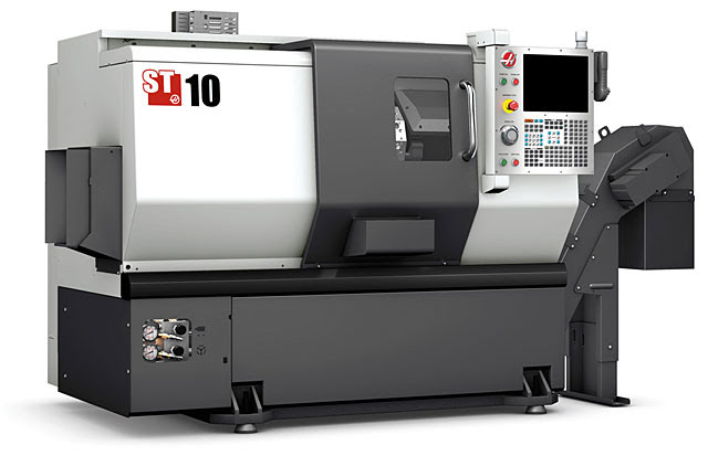
Стандартное оснащение ST-10 включает систему жесткого нарезания резьбы, 15-дюймовый цветной жидкокристаллический дисплей и подключение через USB-порт. Доступное высокопроизводительное оснащение включает приводные инструменты с высоким крутящим моментом и осью C, конвейер ленточного типа для удаления стружки, гидравлическую заднюю бабку, автоматическую измерительную головку для контроля состояния инструментов, автоматический приемник деталей, системы СОЖ высокого давления и многое другое.
Произведенные в США компанией Haas токарно-револьверные станки обеспечены поддержкой всемирной сети фирменных магазинов Haas — самой широкой системы поддержки и сервисного обслуживания в отрасли.
Источник
Свяжитесь с нами
Результаты поиска
Web Pages
Images
ЗАГРУЗИТЬ ЦЕНОВОЕ ПРЕДЛОЖЕНИЕ НА ЛЮБОЙ СТАНОК HAAS
美元价格不包括关税、报关费用、保险费、增值税及运费。
USD prices DO NOT include customs duty, customs fees, insurance, VAT, or freight.
人民币价格包含关税、报关费用、货运保险和增值税, 但不包括运费。
CNY prices include customs duty, customs fees, insurance, and VAT. DOES NOT include freight.
Цены на доставку Haas
Эта цена включает стоимость доставки, экспортные и импортные пошлины, страхование и любые другие расходы, понесенные во время доставки в место во Франции, согласованные с вами в качестве покупателя. Никакие другие обязательные расходы не могут быть добавлены к поставке продукта Haas CNC.
Шпиндели
Револьверная головка и приводной инструмент
- 12-позиционная инструментальная револьверная головка ВОТ
- 12-позиционная инструментальная револьверная головка VDI
Удаление стружки и СОЖ
Блок управления Haas
- Сенсорный экран управления
- М-код медиа дисплея; M130
- HaasConnect: Удаленный мониторинг
- Модуль раннего обнаружения нарушения энергоснабжения
- Интерфейс Ethernet
- Беспроводное подключение для блока управления Haas
- Режим безопасной работы
- HaasDrop
- Жесткое нарезание резьбы метчиком
- Стандартная программная память, 1 гигабайт
- Внутренний разделительный трансформатор высокого напряжения
Инструментарий и зажим
Крепление
Доставка
Гарантия
* Not all options are compatible with each other. Some options may require the purchase of additional options, or may include additional options at no charge. Please use our Build-&-Price tool to determine option compatibility, and configure your machine.
Высокопроизводительные токарные центры Haas серии ST были созданы с нуля для обеспечения гибкости настройки, чрезвычайной жесткости и высокой температурной стабильности.
ST-10 имеет очень маленькую занимаемую площадь, но несмотря на это предоставляет большую рабочую зону. Этот станок представляет лучшее соотношение по цене и качеству в своем классе.
- Очень маленькая занимаемая площадь
- Высокое кол-во оборотов в минуту и быстрота
- Идеален для больших объемов, высокопроизводительной работы
- Сделано в США
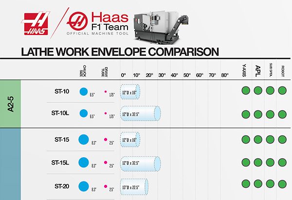
ТАБЛИЦА РАБОЧЕЙ ЗОНЫ ТОКАРНОГО СТАНКА HAAS
РАЗМЕР ПАТРОНА | НАИБОЛЬШИЙ ДИАМЕТР ПРУТКА | РАБОЧАЯ ЗОНА | ОПЦИИ АВТОМАТИЗАЦИИ


ST-10 в эксплуатации
С его большой занимаемой площадью и малым ходом ST-10 просто создан для сложных деталей. Здесь мы видим подпорный штоф, оборачивающийся между центрами. Благодаря отличной износоустойчивости ST-10, мы смогли достичь зеркального качества поверхности, несмотря на коэффициент длины-к-диаметру почти 10:1, без необходимости замедлять подачу/скорость.
Токарные многоцелевые станки серии ST-10
Ознакомьтесь с возможностями и функциями станка ST-10 и остальных станков серии ST-10.

| Наименование параметров | Ед.изм. | Величины |
| Максимальный диаметр точения над станиной | мм |
| Capacities | S.A.E | METRIC |
|---|---|---|
| Размер патрона | 6.5 in | 165 mm |
| Максимальный диаметр обрабатываемой детали | 16.5 in | 419 mm |
| Максимальный диаметр обработки (с револьверной головкой с креплением по стандарту BOT) | 12.00 in | 305 mm |
| Max Cutting Diameter (with VB turret) | 12.00 in | 305 mm |
| Max Cutting Diameter (with VDI turret) | 6.80 in | 173 mm |
| Максимальная длина резания (зависит от крепления) | 16.0 in | 406 mm |
| Наибольший диаметр прутка | 1.75 in | 44 mm |
| Ходы | S.A.E | METRIC |
|---|---|---|
| Ось X | 7.9 in | 200 mm |
| Ось Z | 16.0 in | 406 mm |
| Feedrates | S.A.E | METRIC |
|---|---|---|
| Ускоренные перемещения по оси X | 1200 ipm | 30.5 m/min |
| Быстрые перемещения по оси Z | 1200 ipm | 30.5 m/min |
| Axis Motors | S.A.E | METRIC |
|---|---|---|
| Максимальное осевое усилие вдоль оси X | 3300 lbf | 14679 N |
| Максимальное осевое усилие вдоль оси Z | 3300 lbf | 14679 N |
| Spindle | S.A.E | METRIC |
|---|---|---|
| Торец шпинделя | A2-5 | A2-5 |
| Максимальная мощность | 15.0 hp | 11.2 kW |
| Максимальная скорость | 6000 rpm | 6000 rpm |
| Максимальный крутящий момент | 75.0 ft-lbf @ 1300 rpm | 102.0 Nm @ 1300 rpm |
| Диаметр отверстия шпинделя | 2.31 in | 58.7 mm |
| Turret | S.A.E | METRIC |
|---|---|---|
| Количество инструментов | 12-Station BOT | 12-Station BOT |
| Инструменты для обработки наружных и внутренних диаметров | Any Combination (will vary with turret) | Any Combination (will vary with turret) |
| Втулка расточной оправки (сзади револьверной головки) | 0.75 in | 19.1 mm |
| Общие сведения | S.A.E | METRIC |
|---|---|---|
| Объем СОЖ | 30 gal | 114 L |
| Air Requirements | S.A.E | METRIC |
|---|---|---|
| Требуемое количество сжатого воздуха | 4 scfm @ 100 psi | 113 L/min @ 6.9 bar |
| Встроенный воздушный шланг | 3/8 in | 3/8 in |
| Муфта (пневматическая) | 3/8 in | 3/8 in |
| Минимальное давление воздуха | 80 psi | 5.5 bar |
| Electrical Specification | S.A.E | METRIC |
|---|---|---|
| Скорость вращения шпинделя | 6000 rpm | 6000 rpm |
| Система привода | Direct Speed, Belt Drive | Direct Speed, Belt Drive |
| Мощность, передаваемая шпинделем | 15.0 hp | 11.2 kW |
| Напряжение переменного тока на входе (трехфазный): низкое | 220 VAC | 220 VAC |
| Полная нагрузка, амперы (трехфазный): минимальная | 40 A | 40 A |
| Input AC Voltage (3 Phase) — High* | 440 VAC | 440 VAC |
| Full Load Amps (3 Phase) — High* | 20 A | 20 A |
| Dimensions — Shipping | S.A.E | METRIC |
|---|---|---|
| Спутник для внутренних перевозок | 126 in x 70 in x 81 in | 320 cm x 178 cm x 206 cm |
| Экспортный спутник | 126 in x 70 in x 81 in | 320 cm x 178 cm x 206 cm |
| Масса | 7900 lb | 3585.0 kg |
*Станки Haas предназначены для работы от напряжения сети 220 В перем. тока. Для всех моделей, кроме настольного фрезерного станка CL-1 и CM-1, имеется дополнительный внутренний высоковольтный трансформатор (380–480 В переменного тока).
Примечание. Этот дополнительный высоковольтный внутренний трансформатор не может быть установлен на месте эксплуатации; его необходимо заказывать вместе со станком.
Источник