-
Contents
-
Table of Contents
-
Bookmarks
Quick Links
Related Manuals for Korg TRITON Extreme
Summary of Contents for Korg TRITON Extreme
-
Page 2: About This Manual
References to the TRITON Extreme that can use the BPM/MIDI Sync function. The TRITON Extreme is available in 88-key, 76-key and 61- key models, but both models are referred to without distinc- Example screen displays tion in this manual as “the TRITON Extreme.”…
-
Page 3: Table Of Contents
Keyboard tracking and controller settings 3–6: Filter2 Mod. Table of Contents to modulate the filter 2 cutoff frequency …………..22 3–7: Filter2 LFO Mod. Filter 2 LFO settings to modulate the filter 2 cutoff frequency ……..22 3–8: Filter2 EG Filter 2 EG settings ……..
-
Page 4
2. Combination mode..37 Combination P7: Edit–Arp…….49 Make settings for arpeggiators A and B. 7–1: Setup Assign arpeggiators to each timbre ..49 7–2: Arpegg. A Select an arpeggio pattern and make settings for arpeggiator A …….50 7–3: Arpegg. -
Page 5
3. Sequencer mode ..55 Sequencer P4: Zone/Ctrl…….. 76 Specify the note range and controllers for each track. 4–1: Key Z 1–8 Specify the range of keys sounded by each track …………76 4–2: Key Z 9–16 ………….. -
Page 6
Sequencer P9: Master Effect……98 Sampling P5: Audio CD ……. 138 Make settings for the master effects, the master EQ, and Play back an audio CD, and rip samples from an audio Valve Force. 9–1: Master FX Select master effects and turn them on/ 5–1: Audio CD Play back an audio CD and rip …..138 off, and make chain settings …. -
Page 7
Global P0: Basic Setup………155 7–4: Arpegg. B Select an arpeggio pattern and make Make basic settings that affect the entire TRITON Extreme, settings for arpeggiator B ….. 150 and make AUDIO INPUT settings for other than Sampling 7–5: Scan Zone Specify the range of notes and velocities mode. -
Page 8
7. Media mode … . 175 8. Effect Guide… . . 205 Files, directories, and icons …………175 Overview……….205 0–1: Load Load the selected file or directory into internal memory …….. -
Page 9
021: St. Random Flanger (Stereo Random Flanger) ……228 066: Comp – Param4EQ (Compressor – Parametric 4-Band EQ) ..251 022: St. Env. Flanger (Stereo Envelope Flanger) ……229 067: Comp – Cho/Flng (Compressor – Chorus/Flanger)….251 023: Stereo Phaser …………….229 068: Comp –… -
Page 10
……..285 MIDI applications……..288 ■ About MIDI ………………288 ■ Connecting MIDI devices/computers (MIDI connectors)….288 ■ Messages transmitted and received by the TRITON Extreme ..289 TRITON Extreme MIDI IMPLEMENTATION ..299 Various messages……..302 Data compatibility……..309 Media mode information …… -
Page 12: Program Mode
EXB-MOSS programs will be available. Category [00…15] The TRITON Extreme provides rewritable banks A–E and Selects the program category. H–N, each containing 128 programs (total 1,536). As non- All programs are classified into one of sixteen categories.
-
Page 13
10’s Hold Pitch Stretch [–12…+00…+12] This simultaneously adjusts the Transpose and Tune of the 1 Press the [./10’s HOLD] key to display oscillator. This lets you produce a variety of tonal changes The 10’s place of the program number will be held and variations without loosing the character of the original (fixed). -
Page 14
IFX Balance [–10…0…+10] With the factory settings, the program categories have been given the names of instruments etc., but you can use This adjusts the “Wet/Dry” setting of insert effects 1–5 as a “Program Cat.” (Global P4: 4–1) to modify these category whole. -
Page 15: 0-2: Arpeggio
This lets you sample an external audio signal sent to the L/R bus (specified by “Input” 0–3a), or the sounds sent to the L/ R bus from a performance played on the TRITON Extreme from its keyboard or via MIDI input.
-
Page 16
INDIVIDUAL 1, 2, 1/2 buses from a performance played on down when you begin sampling with the “Trigger” setting the TRITON Extreme from its keyboard or via MIDI input. Sampling START SW. This can be set only if “Trigger” is set to Sampling START Normally when you want to sample a performance in Pro- gram mode, you will select L/R. -
Page 17
Sample Time [min sec] The “Auto +12 dB On” setting will not affect samples that you recorded to the media when “Save to” (0–3b) Specifies the length of time that you want to sample. This is set to MEDIA. You can use “WAVE File Play Level” can be set in units of minutes and 0.001 second. -
Page 18: Audio Inputs Etc
0–3D: Select Director y 1 Select “Select Bank & Smpl No.” to access the dialog box. This lets you select the disk (internal hard disk, etc.) and directory on which the WAVE file created by sampling will be saved, and specify a filename. You will also choose this “Select Directory”…
-
Page 19
1 Select “Auto Sampling Setup” to open the dialog box. c) If you want to change the RAM bank into which the data will be sampled (when using “Save to” RAM), use the page menu command “Select Bank & Smpl No.” (0– 3C). -
Page 20: Program P1: Edit-Basic
If you want to hear the sound that is being sampled, use Program P1: Edit–Basic INDIV. 1, 2 OUT. Connect AUDIO OUTPUT MAIN L, R, INDIV 1, 2 to your mixer or audio system, and moni- Here you can adjust basic program settings, such as oscilla- tor the output.
-
Page 21
When legato is on, multiple note-on message will not retrig- Pelog: This is an Indonesian gamelan scale in which an ger the voice. If one note is already on and another note is octave consists of seven notes. turned on, the oscillator sound, envelope, and LFO will not When “Key”… -
Page 22: 1-2: Osc Basic
1–2: OSC Basic MS Bank Mbyte Explanation 000–424 TRITON Classic preset multisamples The multisample(s) (waveform) or drum kit on which the program will be based can be selected here for oscillator 1 000–999 RAM multisamples (created in Sam- pling mode or loaded in Media mode) and/or oscillator 2.
-
Page 23
multisample play backward. Preset multisamples that have 1–2c: Velocity M.Sample SW Lo → Hi a loop setting and RAM multisamples for which you’ve (Velocity Multisample Switch Low → High) made loop settings in Sampling mode will play backward in one-shot mode. Multisamples that are already set to Reverse OSC1 (OSC1 Velocity Switch) [1…127] will simply play back that way. -
Page 24
4 Press the Done button to execute, and close the dialog ▼ 1–2: Page Menu Command box. Please be aware that the Compare function is not avail- 0–1A able for this command. 1–1A 1–1B 1–2A 1–3: Velo. Zone (Velocity Zone) 1–2A: Sample Parameters Here you can specify the velocity range at which each oscil- lator will sound. -
Page 25: And 2
1–4: Controller (Controller Setup) Program P2: Edit–Pitch These settings specify the functions of the [SW1] key, the [SW2] key, and the B-mode functions of REALTIME CON- Here you can make pitch modulation settings for oscillators TROL knobs [1]–[4] in Program mode. 1 and 2.
-
Page 26
For example if you set this to +12 and move the joystick all If [SW1] key or [SW2] key are set to Porta.SW:CC#65, turning the way to the right, the pitch will rise one octave above the [SW1] key or [SW2] key on/off will apply portamento (“AMS List”… -
Page 27: 2-2: Osc2 P.mod
LFO2: Release (Release Level) [–99…+99] Specifies the amount of pitch change when the release time LFO2 Intensity [–12.00…+12.00] has elapsed. JS+Y Int. (LFO2 JS+Y Int.) [–12.00…+12.00] Time: AMS (LFO2 AMS) [Off, (PEG, FEG, AEG, KT, EXT)] These parameters specify the amount of time over which the Intensity (AMS Intensity) [–12.00…+12.00] pitch change will occur.
-
Page 28
St (AMS1 SW Start) [–, 0, +] At (AMS SW Attack) [–, 0, +] Specifies the direction of change in “Start (Start Level)” Specifies the direction in which “AMS (Time Mod. AMS)” will caused by “AMS1 (Level Mod. AMS1).” If “Intensity affect the “Attack (Attack Time).”… -
Page 29: Program P3: Edit-Filter
Frequency (A Frequency) [00…99] Program P3: Edit–Filter Specifies the cutoff frequency of filter 1A. Resonance (A Resonance) [00…99] Here you can make settings for the filters that will be used by oscillators 1 and 2. You can select either a 24 dB/octave low This emphasizes the overtone components that lie in the pass filter with resonance, or a series connection of a 12 dB/ region of the cutoff frequency specified by “Frequency (A…
-
Page 30
3–2: Filter1 Mod. How cutoff frequency is affected by keyboard location and the Ramp setting (“Intensity to A” and “Intensity to B” = +50) Here you can make settings to specify how keyboard track- ing, controllers, and filter 1 EG intensity will control the Fil- Cutoff frequency High Ramp=+99 ter 1 cutoff frequency “Frequency”… -
Page 31
3–3: Filter1 LFO Mod. Intensity to B [–99…+99] Specifies the depth and direction of the effect that the time- Here you can use the filter 1 LFO to apply cyclic modulation varying changes created by the filter 1 EG will have on the to the cutoff frequency of filter 1 (for oscillator 1) to create filter 1B cutoff frequency (☞“Intensity to A”). -
Page 32: 3-4: Filter1 Eg
Release (Release Level) [–99…+99] 3–3b: LFO 2 Specifies the cutoff frequency that will occur when the release time has elapsed. Adjusts the depth of the cyclic modulation applied by OSC1 LFO2 (set by 5–2) to the cutoff frequency of filters 1A and 1B Time: (☞LFO 1: 3–3a).
-
Page 33: 3-5: Filter2
Br (AMS SW Break) [–, 0, +] Rl (AMS1 SW Release) [–, 0, +] Specifies the direction in which “AMS (Level Mod. AMS)” Specifies the direction in which “AMS1 (Time Mod. AMS1)” will affect “Break (Break Point Level).” When “Intensity will affect the release time.
-
Page 34: Program P4: Edit-Amp
Intensity [–99…+99] Program P4: Edit–Amp Specifies the depth of the effect produced by “AMS (Pan AMS).” Make settings for amp 1 which controls the volume of oscil- For example if “Pan (Amp1 Pan)” is set to C064 and “AMS lator 1, and amp 2 which controls the volume of oscillator 2. (Pan AMS)”…
-
Page 35
Ramp High (KBDTrk Ramp High) [–99…+99] AMS (LFO1 AMS) [Off, (PEG, FEG, AEG, KT, EXT)] With positive (+) values of this parameter, the volume will Selects a source that will control the depth by which “OSC1 increase as you play notes above the “Key High (KBDTrk LFO1”… -
Page 36
Time: Br (AMS SW Break) [–, 0, +] Attack (Attack Time) [00…99] Specifies the direction in which “AMS (Level Mod.AMS)” will change “Break (Break Point Level).” If “Intensity (AMS Specifies the time over which the volume will change after Intensity)” is set to a positive (+) value, setting this parame- note-on until it reaches the attack level. -
Page 37: 4-6: Amp2 Eg
Rl (AMS1 SW Release) [–, 0, +] Program P5: Edit–Common LFO Specifies the direction of the effect that “AMS1 (Time Mod. AMS1)” will have on “Release (Release Time).” With posi- Here you can make settings for the LFO that can be used to tive (+) values of “Intensity (AMS1 Intensity),”…
-
Page 38: 5-2: Osc1 Lfo2
Offset settings and pitch change produced by vibrato 5–1c: Frequency MIDI/Tempo Sync. Pitch offset = –99 offset = 0 offset = +99 MIDI/Tempo Sync. [Off, On] On (checked): The LFO frequency will synchronize to the Pitch at note-on tempo (MIDI Clock). In this case, the values you specified for “Frequency”…
-
Page 39: Program P7: Edit-Arpeggiator
7–1b: Arpeggiator Setup Program P7: Edit-Arpeggiator ☞Refer to OG p.94. Here you can make settings for the arpeggiator used by the program. Pattern* [P000…P004, U000(A/B)…U506(User)] You can make settings so that when you select a program, Selects the arpeggio pattern. these arpeggiator settings will automatically switch to the arpeggiator settings that are memorized in the selected pro- P000…P004…
-
Page 40: 7-2: Scan Zone
Swing [–100…+100(%)] ▼ 7–1: Page Menu Command This parameter shifts the timing of the odd-numbered notes of the arpeggio. 0–1A 7–1A When Resolution = Step 1 7–1A: Copy Arpeggiator This command can be used to copy arpeggio settings from another location to the current program. –50 –25 1 Select “Copy Arpeggiator”…
-
Page 41: Program P8: Edit-Insert Effect
put the sound from (MAIN) L/MONO and R, the pan- Program P8: Edit–Insert Effect ning will not move in realtime while the note is sounding. ☞For details on insert effects, refer to p.205 “8. Effect If you wish to adjust the pan in realtime during a note Guide.”…
-
Page 42: 8-2: Insert Fx
2 In “From” select the source mode, bank, and number of 8–2a: IFX1, 2, 3, 4, 5 the effect to be copied. IFX1, 5 [000…089] You can select a bank by pressing the BANK [A]–[N] keys. IFX2, 3, 4 [000…102] Selects the type of each insert effect.
-
Page 43: 8-3: Ifx 1
BUS Sel. (BUS Select) Program P9: Edit–Master Effect [L/R, 1, 2, 3(Tube), 4(Tube), 1/2, 3/4(Tube), Off] Specifies the bus to which the sound will be sent after pass- ☞For details on the master effects, refer to p.205 “8. Effect ing through the insert effect. Normally you will set this to L/ Guide.”…
-
Page 44
MFX1, 2 On/Off [Off, ON] ▼ 9–1: Page Menu Command Switches the master effects 1, 2 on/off. When off, the output will be muted. This will alternate between on and off each 0–1A time it is pressed. 9–1A CC#94 can be used to switch the MFX on and off. A 9–1B value of 0 will be off, and a value of 1–127 will be the original setting. -
Page 45: 9-2: Mfx 1
9–2: MFX 1 9–5: VALVE FORCE 9–3: MFX 2 Here you can adjust the Valve Force settings. Valve Force is an analog circuit that uses a vacuum tube (a.k.a., “valve”). Makes effect parameter settings for the MFX1 and 2 effects By using Valve Force either alone, in conjunction with an that were selected in the Master FX page (9–2).
-
Page 46
You can also use the VALVE FORCE [OUTPUT LEVEL] Placement: Insert (Use 3/4 BUS) knob to set this. Digital Analog Valve Force You can use MIDI NRPN control change messages to Volume On/Off 3/4 (Tube) BUS AUDIO OUTPUT control the VALVE FORCE [ON/OFF] key and the INDIV. -
Page 47
Send1 [000…127] Send2 [000…127] These specify the levels at which the signal that has passed through Valve Force will be sent to master effects 1 and 2. These parameters are valid if “BUS Sel.” is set to L/R or Off. You can control these parameters using CC#93 and CC#91, on the global MIDI channel specified by MIDI Channel (Global P1). -
Page 48: Combination Mode
2. Combination mode 1 Press the popup button located at the left of “Combina- Combination P0: Play tion Select” to access the Bank/Combination Select menu. In this display page you can select and play Combinations. 2 Press one of the tabs located at the left or right to select a A Combi allows you to use up to eight programs at once.
-
Page 49
Bank/Program (Program Select) mitted. [A…F, G, g(1)…g(9), g(d), H…N] EXT: Playing TRITON Extreme will not cause it to sound, Specifies the program that will be used by the timbre. but it will transmit data via MIDI to control external MIDI Part of the program name is displayed in the line below. -
Page 50
2 Use “Program” to select the copy-source program. ▼ 0–1: Page Menu Command 3 If you check “with Effects,” the insert effect, master effect, and master EQ settings will also be copied. The “Control Channel” of each effect will be set to the MIDI 0–1A channel of the copy-destination timbre. -
Page 51: 0-2: Mixer
The settings that will be automatically made for the If “Status” (0–1c, 2–1b) has been set to INT, MIDI con- combination are the same as when you execute the trol change #10 (panpot) messages can be received to page menu command “Copy From Combi” (0–1F) with control the setting.
-
Page 52: 0-5: Sampling
TRITON Extreme performance. (☞Program P0: 0–3) Adjusts the signal level at the final stage of sampling in The TRITON Extreme can also be used as a 4-in 6-out effect Combination mode. (☞Sampling P0: 0–1d) processor.
-
Page 53: Combination P1: Edit-Program/Mixer
0–5A: Auto Sampling Setup Combination P1: Edit–Program/Mixer This command automatically sets sampling-related parame- ters in Combination mode. This is a helpful convenience when you’re resampling your performance on a combina- tion, or when you’re using a combination as a guide while 1–1: Program/Mixer sampling an external source.
-
Page 54: Combination P2: Edit-Trk Param
If this is set to EXT or EX2, playing the TRITON Extreme will transmit MIDI messages tings. (If the setting is PRG, CC#05 portamento time on the MIDI channel specified here.
-
Page 55: 2-3: Pitch
12 units equal one octave. When “Status” (0–1c, 2–1b) is INT, this parameter will affect the pitches sounded by the TRITON Extreme. When “Status” is EXT, this parameter will affect the 2 In “From” specify the original BPM value. In “To” spec- note numbers of the MIDI note messages that are trans- ify the desired BPM value.
-
Page 56: 2-4: Other
MIDI data on that timbre’s MIDI chan- nel. MIDI transmission and reception settings for the entire 2–4a: Delay, Use Program’s Scale, Scale TRITON Extreme are made in “MIDI Filter” (Global P1: 1– 1b). Delay [ms] (Delay Time) [0000…5000, KeyOff]…
-
Page 57: 3-2: Midi 2
3–2a: Enable JS X as AMS, Enable JS+Y, Specifies whether or not the A-mode MIDI control message Enable JS–Y, Enable Ribbon CC#79 (the TRITON Extreme’s filter EG intensity) and the B- Enable JS X as AMS [Off, On] mode MIDI control message assigned to knob [3] will be transmitted and received.
-
Page 58: Combination P4: Edit-Zone/Ctrl
Bottom Slope [00…72] Combination P4: Edit–Zone/Ctrl Specifies the range of keys (12 is one octave) over which the volume will be reached starting from the bottom key. 0: The volume will be at the original level from the bottom 4–1: Key Z key.
-
Page 59: Timbre
4–4: Controller (Control) 4–2a: Top Velocity, Top Slope, Bottom Slope, Bottom Velocity Here you can set the Combination mode functions of the [SW1] key, [SW2] key, and the B-mode functions of REAL- Top Velocity [1…127] TIME CONTROL knobs [1]–[4]. Specifies the maximum velocity value that will sound each 0–1A timbre 1–8.
-
Page 60: Timbre 2
TRITON Extreme’s Combination P7: Edit–Arp. arpeggiator. If you want the note data generated by the arpeggiator These parameters specify how the arpeggiator will function to be recorded on the external sequencer, turn Local within the combination. Two arpeggiators can run simulta- Control ON, and turn off the echo back function on neously.
-
Page 61: 7-4: Scan Zone
Latch* [Off, On] ▼ 7–1: Page Menu Command Key Sync.* [Off, On] Keyboard* [Off, On] 0–1A These parameters are the arpeggiator settings for the combi- 0–1B nation. (☞“Program P7: Edit-Arpeggiator”) 7–1A * These parameters can also be set from “0–3(4): Arpegg. 0–1C A(B)”.
-
Page 62: Combination P8: Edit-Insert Fx
If you wish to move the pan of a sounding note in real- Combination P8: Edit–Insert FX time and output it from AUDIO OUTPUT (INDIVID- UAL) 1/2 or 3/4, you must set “BUS Select” to IFX1 You can also specify the bus routing for the program used by (or IFX2–IFX5), select 000: No Effect for “IFX1”…
-
Page 63: 8-2: Insert Fx
8–3: IFX 1 2 In the Drum Kit “IFX” popup, select the insert effect to which you want to patch. 8–4: IFX 2 3 To execute the Drum Kit Insert Effect Patch command, press the OK button. To cancel, press the Cancel button. 8–5: IFX 3 To restore the condition of the drum kit, execute IFX1→IFX1, IFX2→IFX2, IFX3→IFX3, IFX4→IFX4, and…
-
Page 64: Combination P9: Edit-Master Fx
9–2: MFX 1 Combination P9: Edit–Master FX 9–3: MFX 2 ☞For details on master effects, refer to p.205 “8. Effect Here you can set the parameters for the MFX 1 and 2 effects Guide.” that were selected in the Master FX page (☞p.217–). 9–1 9–1: Master FX 9–2a…
-
Page 65
9–5: VALVE FORCE Post-IFX “Send1,” “Send2”: as desired Post-IFX “BUS Sel.”: L/R or 1/2 Here you can adjust the settings of the Valve Force analog Don’t set the post-IFX “BUS Sel.” to 3/4(Tube), since vacuum tube circuit. doing will cause a feedback loop that may produce You can apply Valve Force to single or multiple timbres, unpleasant distortion. -
Page 66: Sequencer Mode
In addition to recording MIDI data on these tracks, you can 0–1b record and edit patterns. Patterns you create or the preset patterns provided by the TRITON Extreme can be copied to 0–1c a track, or used with the RPPR function.
-
Page 67
(Tempo)” setting while a song is playing or recording (or Use “Track Name” (5–2) to specify the track name. during standby). When you play the keyboard of the TRITON Extreme Manu (Manual): The “ (Tempo)” setting will be used. and operate its controllers, the internal tone generator REC: Tempo changes will be recorded on the Master Track. -
Page 68
mitted on the MIDI channels of these tracks (whose 0–1(2)c: Track Number, Category, Bank/Program, “Status” is EXT, EX2 or BOTH). PLAY/MUTE/REC, SOLO ON/OFF Master Track: The Master Track manages overall sequencer Track Number (1…8 (9…16)) functions such as tempo and time signature. Select the mas- ter track if you want to use the P5: Track Edit page menu Indicates the MIDI track number. -
Page 69
SOLO ON/OFF [SOLO ON, SOLO OFF] 0–1D: Delete Song This turns the Solo function on/off. This command deletes the currently selected song. Only the track that is set to SOLO ON will sound. Other 1 Select “Delete Song” to access the dialog box. tracks will be muted. -
Page 70
This function makes adjustments depending on the Make sure that the global MIDI channel (Global P1: MIDI, ARPEGGIATOR [ON/OFF] state of the combination. “MIDI Channel”) is set to 01. When you copy a combination that was written with Arpeggiator Run MIDI Channel Correction the arpeggiator turned off, it is assumed that you will… -
Page 71
0–1G: Load Template Song Track 1 of all sixteen preset template songs contains a drum category program. (In preset template songs P02, This command loads a template song as a song. P04, P08, and P15 drum category programs are speci- The built-in sequencer contains sixteen different preset tem- fied for multiple tracks.) plate songs (P00–15) that contain preset settings for pro-… -
Page 72
0–1I: FF/REW Speed 2 In “Location,” specify the location to which you will move when you press the [LOCATE] key. If you specify This allows you to set the speed at which fast-forward or 001:01.000, you will move to the beginning of the song rewind will occur when you press the [FF] key or [REW] when you press the [LOCATE] key. -
Page 73: 0-3: Mixer
0–3: Mixer 1–8 If “Status” (2–1a/2a) is INT or BTH, CC#10 Panpot can (Mixer T01–08) be received to control the panning. When receiving 0–4: Mixer 9–16 (Mixer T09–16) CC#10, a value of 0 or 1 is far left, 64 is center, and 127 is far right.
-
Page 74: 0-7: Sampling
You can sample either an external audio signal, or a perfor- Sequencer mode, not to individual songs. mance played on the TRITON Extreme. The TRITON Extreme can also be used as a 4-in 6-out effect processor. (☞Program P0: 0–3) 0–7c: Recording Level [dB]…
-
Page 75
If you check the “Seq.Event” check box, a note event will automatically be created in the track specified by “Track.” Note-on will occur at the location at which sam- pling began, and note-off will occur at the location at which sampling ended. The note event will be created as in “Recording Setup”… -
Page 76
DAT player etc. connected to the S/P DIF If you select RAM, the data will be written to sample IN jack will be input to the TRITON Extreme. (P0: 0–7a memory (RAM). If you select MEDIA, the data will be “Input,”… -
Page 77
To change the way in which sampling is initiated, Press the OK button to execute “2ch Mix to Media,” or change the “Trigger” setting. If you set this to Thresh- press the Cancel button if you decide to cancel. (☞For old, resampling will begin the instant the input level the parameters and values that will be set, refer to p.66) exceeds the specified value. -
Page 78: 0-8: Preference
MIDI M*** (Auto Punch In Start Measure–Auto Punch In End Mea- data it transmits in one pass into the TRITON Extreme’s sure)” at the right, allowing you to specify the range of mea- sequencer (☞OG p.45).
-
Page 79: You Can Make Metronome Settings
“Track Select.” sion. You can specify a number of repetitions for each song. The TRITON Extreme allows you to create twenty cue lists. This cannot be selected if “Recording Mode” is set to In a single cue list you can freely connect up to 99 songs.
-
Page 80
Meter (Time Signature) [1/4…16/16] “Step” indicates each step number. The “Step” indicated by symbol is the currently-selected or currently-playing This displays the time signature of the currently-playing step. This can be directly selected by “Song” (1–1c) or “Cur- song. rent Step” (1–1d). When stopped, pressing the SEQUENCER (Tempo) [040…240] [START/STOP] key will cause playback to begin from this… -
Page 81
3 To execute the Copy Cue List command, press the OK 1–1d: Insert, Cut, Copy, Current Step button. To cancel, press the Cancel button. When you execute, the setting data of the selected cue list Insert will be deleted, and replaced by the copy-source data. When you press the Insert button, the step data that was 1–1D: Convert to Song (Convert Cue List to Song) temporarily saved in the buffer by the Copy button or Cut… -
Page 82
If “Pan” (0–3a/4a) is RDN, it will be converted to C064. sion. In particular if the cue list uses long songs, or if If “Portamento” (2–3a/4a) is PRG, or if “Bend Range” numerous repeats have been specified, or if many pat- (2–5a/6a) is PRG or a negative value, these will not be terns are used by the songs, you should try executing reflected in the conversion. -
Page 83: Sequencer P2: Trk Param
Selects the Voice Assign Mode (Program P1: 1–1b) of the pro- nal tone generator of the TRITON Extreme will sound, and gram selected for each track 1–16 (☞Combination P2: 2–2a).
-
Page 84: 2-5: Pitch
CC#65 of 127 and CC#05 of 1–127 will be transmitted. ▼ 2–5: Page Menu Command If this is set to PRG, nothing will be transmitted. This data is transmitted and received on the MIDI chan- nel specified for each track by “MIDI Channel” (2–1a/ 0–1A 0–1G 2a).
-
Page 85: Sequencer P3: Midi Filter
MIDI data is received. (The effect dynamic modulation function is not affected by these set- tings.) Settings that regulate MIDI transmission/reception of the TRITON Extreme itself are made in MIDI Filter (Glo- bal P1: 1–1b). If the user-assignable controllers that can be filtered in the MIDI 3 and MIDI 4 pages are set to MIDI control changes, filtering will be performed for these control changes.
-
Page 86: 3-3: Midi
Specifies whether or not MIDI control message CC#1 (the +Y high pass filter cutoff frequency) and the B-mode MIDI con- axis of the TRITON Extreme’s joystick, or assigned to B- trol message will be received. mode of the REALTIME CONTROL knobs [1]–[4]) will be received.
-
Page 87: 3-7: Midi
3–7: MIDI 4 1–8 (MIDI Filter –4 T01–08) Sequencer P4: Zone/Ctrl 3–8: MIDI 4 9–16 (MIDI Filter –4 T09–16) 0–1 4–1: Key Z 1–8 (Key Zone T01–08) 0–1a 0–1b 0–3a 4–2: Key Z 9–16 (Key Zone T09–16) Here you can specify the range of keys that will play tracks 1–16.
-
Page 88: 4-3: Vel Z
4–3: Vel Z 1–8 4–7: Controller (Vel Zone T01–08) (Controller Setup) 4–4: Vel Z 9–16 Here you can set the functions that the [SW1] key, [SW2] key, (Vel Zone T09–16) and the B-mode functions that the REALTIME CONTROL Here you can set the Top/Bottom Velocity parameters to knobs [1]–[4] will have in Sequencer mode.
-
Page 89: Sequencer P5: Track Edit
▼ 5–1: Page Menu Command Sequencer P5: Track Edit 5–1G 0–1A 5–1N 5–1H 5–1A 5–1O 5–1: Track Edit 5–1I 5–1B 5–1P 5–1J 5–1C 0–1I Here you can edit MIDI tracks, and the master track. 5–1K 5–1D 0–1J When editing a MIDI track, you can move, insert, and delete 5–1E 5–1Q individual events of note or control change data, or copy,…
-
Page 90
The following table shows the number of clocks repre- 8 When you are finished with step recording, press the sented by each “Step Time” selection. Done button. If you press the [COMPARE] key, you will return to the condition of before you began step record- ing. -
Page 91
5–1C: Erase Track • Deleting an event Select the event that you wish to delete, and press the This command erases the data from the specified track. Cut button to delete the event. However, it is not possible to erase the master track by itself. •… -
Page 92
5–1F: Erase Measure 1 Use “Track Select” to select the MIDI track (Track 01–16) that contains the measures you want to delete. This command erases the specified type(s) of musical data 2 Select “Delete Measure” to access the dialog box. from the specified range of measures. -
Page 93
1 Use “Track Select” to select the MIDI track (Track 01–16) 2 Select “Repeat Measure” to access the dialog box. that you want to insert data into. 2 Select “Insert Measure” to access the dialog box. 3 In “From Measure” and “To End of Measure,” specify the range of measures that will be repeated. -
Page 94
6 To execute the Copy Measure operation, press the OK 4 “Kind” to the type of musical data (event) that you wish button. To cancel, press the Cancel button. to create. Control change: Control change data will be inserted. In this case, use “#”… -
Page 95
If you wish to erase all control change data from speci- 6 In “Offset,” specify the number of clock ticks by which fied measures, you can also use “Erase Measure” (5–1F) the data will be moved forward or backward relative to and set “Kind”… -
Page 96
2 Select “Shift/Erase Note” to access the dialog box. 3 Specify the range in which note velocity will be modified. “From Measure” and “To End of Measure” specify the measure, and “Beat.Tick” specify the beat and clock. (By default, “From Measure” and “To End of Measure” will be set to the range that you specified in the Track Edit page.) 4 Specify the range of notes that will be affected by the… -
Page 97: 5-2: Track Name
5–2: Track Name 5–3(4)(5)(6)(7)(8)a: Tone Adjust 1–Tone Adjust 6 Here you can assign a name to each track. Destination [LPF Cutoff…Reverse] 5–1 Assigns a parameter to each of the Tone Adjust controls. 0–1a Value [–99…+99, –199…+199, –12.00…+12.00, –1200…+1200, Off…On] 5–1b 0–1b Specifies the value of the parameter selected in “Destina- tion.”…
-
Page 98
Filtr EG A (Filter EG Attack) [–99…+00…+99] Dtun 2 (Detune 2) [–1200…+0000…+1200] Filtr EG D (Filter EG Decay) [–99…+00…+99] Adjusts the tuning of program OSC2. This controls the OSC2 Multisample “Tune” parameter (Program P1: 1–2a). Filtr EG S (Filter EG Sustain) [–99…+00…+99] Filtr EG R (Filter EG Release) [–99…+00…+99]… -
Page 99: Sequencer P6: Pattern/Rppr
Selects the type of pattern. If Preset is selected, it will not be possible to record. You will On the TRITON Extreme you can use preset patterns P000– be able to select and execute the “Copy Pattern,” “Bounce 149, and user patterns U00–99. One song can contain up to Pattern,”…
-
Page 100
6–1D: Erase Pattern ▼ 6–1: Page Menu Command This command erases the data from the selected pattern. 1 Use “Pattern” and “Pattern Select” to specify the pattern. 0–1A 6–1F 2 Select “Erase Pattern” to access the dialog box. 6–1G 6–1A 6–1H 6–1B 6–1I… -
Page 101: 6-2: Pattern Name
4 In To: “Song” and “Pattern,” select the bounce destina- If you press the SEQUENCER [START/STOP] key tion song and pattern. For “Pattern,” only user patterns while the dialog box is open, the selected pattern will U00–U99 can be specified. play back.
-
Page 102: 6-3: Rppr Setup
RPPR patterns on Off (unchecked): That key will sound the currently selected TRITON Extreme, set Local Control OFF. track at the corresponding pitch, just as in normal Sequencer If you want the note data generated by RPPR to be mode.
-
Page 103
Sync [Off, Beat, Measure, SEQ] 2 Set “KEY” to D2, and press the Revert button. The “Pattern (Pattern Bank),” “Pattern Select,” and Specifies the way in which the pattern playback will be syn- “Track” settings that you specified in step 1 will be cop- chronized when you press the specified “KEY.”… -
Page 104: Sequencer P7: Arpeggiator
7–1(2)a: Arpeggiator Assign, Arpeggiator Run A, B Sequencer P7: Arpeggiator Arpeggiator Assign [Off, A, B] Here you can specify how the arpeggiator will operate in This assigns arpeggiator A or arpeggiator B to each track 1– Sequencer mode. These settings can be made for each song. 8, 9–16.
-
Page 105: 7-5: Scan Zone
7–3: Arpegg. A • Alternatively, you could choose Track01 in “Track (Arpeggiator A) Select” to run arpeggiator A for tracks 1 and 2, and use 7–4: Arpegg. B (Arpeggiator B) an external MIDI device connected to the TRITON Extreme’s MIDI IN to send note data to MIDI channel 3 In the Arpegg.
-
Page 106: Sequencer P8: Insert Effect
7–5b: Scan Zone A/B Sequencer P8: Insert Effect Here you can make insert effect settings, and specify the bus etc. for the program used by each track 1–16. Top Key [C–1…G9] ☞For details on insert effects, refer to p.205 “8. Effect Bottom Key [C–1…G9] Guide.”…
-
Page 107
Send1 (MFX1) [000…127] 8–1D: Put Effect Setting to Track Send2 (MFX2) [000…127] This command inserts effect settings into a track as exclusive events. You can use this to make the effect settings change Here you can adjust the send levels from tracks 1–16 to mas- during a song. -
Page 108: 8-3: Insert Fx
8–3: Insert FX 8–4: IFX 1 8–5: IFX 2 Here you can select the type of the insert effects, turn them on/off, and make chain settings. 8–6: IFX 3 8–1 8–7: IFX 4 8–8: IFX 5 Set the parameters for the effects selected for IFX 1–5 in the 8–3a Insert FX page (☞p.217–).
-
Page 109: Sequencer P9: Master Effect
9–2: MFX 1 Sequencer P9: Master Effect 9–3: MFX 2 ☞For details on the master effects, refer to p.205 “8. Effect Here you can set the parameters of the MFX 1 and 2 effects Guide.” that were selected in the Master FX page (☞p.217–). 9–1 9–1: Master FX 9–2a…
-
Page 110: 9-5: Valve Force
9–5: VALVE FORCE Example settings) Set “BUS Select” (8–1(2)b) or post-IFX “BUS Sel.” (8–3a) to Here you can adjust the settings of the Valve Force analog insert Valve Force at the desired location. Use Valve Force vacuum tube circuit. “BUS Sel.” (9–5a) to specify the output destination from Valve Force can be applied to specific tracks, either alone or Valve Force.
-
Page 111
▼ 9–5: Page Menu Command 0–1A Program 9–5A 0–1I 0–1J… -
Page 112: Exclusive Events Supported In Sequencer Mode
Exclusive messages that can be realtime-recorded Exclusive events supported in The following exclusive messages can be realtime recorded. Sequencer mode • Exclusive messages received from an external MIDI device • Parameter changes in Sequencer mode (see table below) You can record and play back exclusive events, and edit •…
-
Page 113
Sequencer mode track parameters and effect parameters can be controlled by MIDI system exclusive parameter change messages. When an external sequencer is connected and you use the TRITON Extreme in Sequencer mode as a 16-track multi-timbral sound module, you can control these parame- ters via MIDI. -
Page 114: Sampling Mode
Program, Combination, and Sequencer modes 1. A performance that makes use of the various functions of On the TRITON Extreme, 48 kHz stereo 16-bit samples from each mode (filters, effects, arpeggiator, sequencer, etc.) can an external device connected to the AUDIO INPUT jacks or be resampled.
-
Page 115: Sampling P0: Recording
CD-R/RW or external SCSI device (☞OG p.117). 0–1: Recording When the TRITON Extreme is turned on, the sample memory (RAM) will contain no multisamples or sam- Here you can select the multisample that you wish to record, ples, so you will first need to load previously-saved specify the index sample, make settings, select the memory data into RAM before you can edit it or play it back.
-
Page 116
You can also select an index by holding down the —-: —No Assign—-: No sample is assigned to the index. [ENTER] key and playing a note on the keyboard. The There will be no sound when you play the keyboard. index that includes this note will be selected. -
Page 117
Sample memory (RAM) consists of six banks, each with 16 In these cases, a stereo multisample will be created auto- Mbytes. The TRITON Extreme comes with one 16 Mbyte of matically using the following criteria. DRAM SIMM board. In this state, RAM1 will always be 1. -
Page 118
Sample Time [min sec] Example 1): Sampling a monaural source connected to AUDIO INPUT 1 without applying internal effects Specifies the amount of time that you wish to sample. This “Input” (0–2a) Analog can be set in 0.001 second increments. This parameter indi- cates amount of remaining memory in the selected memory Input1 “Pan”… -
Page 119
▼ 0–1: Page Menu Command 0–1d: Recording Level [dB] Recording Level [–inf, –72.0… 0.0…+18.0] 0–1A 0–1H This adjusts the signal level at the final stage of sampling. 0–1B 0–1I When you sample, make sure that the level is as high as pos- 0–1C 0–1J sible without allowing the level meter to indicate “CLIP!!.”… -
Page 120
3 Specify the sample number of the copy destination. 2 Select “Delete MS” to access the dialog box. When copying a stereo sample, specify both the L and R channels for the copy destination sample number. 4 If you check “with Sample Data”: Executing the copy will simultaneously copy the sample data (waveform data) as well. -
Page 121
and -R. If you rename up to fourteen characters of the to the following pan settings: “Amp 1 Pan” L000, and multisample of either the L or the R channel, the other “Amp 2 Pan” R127 (Program P4: Amp 1 Lvl/Pan page multisample name will automatically be renamed. -
Page 122
3 To execute the Change Sample Type command, press the if the samples being moved are mapped to (used by) a OK button. To cancel, press the Cancel button. drum kit, those sample numbers will also be automati- When you execute this command, the sample type will cally modified. -
Page 123
4 If “Adjust Multisample Assign in Program” is checked 2 Use “Media select” to select the media into which the and if the multisamples being moved are used in pro- data will be written during sampling. grams, the multisample numbers of the programs will 3 Use the Open button and Up button to move between also be reassigned automatically. -
Page 124
If you select Initialize: If you select Auto Resample through IFX: Press the OK button to initialize the settings, or press the Cancel button if you decide not to execute. (☞For the parameters and values that will be set, refer to p.114) If you select REC Audio Input: 1) Use “IFX”… -
Page 125: 0-2: Input/Setup
DAT etc. connected to the S/P DIF IN jack can be input to according to the settings you make in the dialog box. the TRITON Extreme. The L channel of the S/P DIF input :Settings for analog and S/P DIF (“Input 1” and “Input 2”) will be input as specified by the Input1 setting below, and…
-
Page 126
0 after a pre-count of 4– Sampling START SW: Pressing the SAMPLING [REC] key 3–2–1–0. will cause the TRITON Extreme to enter sampling-standby The output destination and level of the metronome mode, and sampling will begin when you press the SAM- sound are specified by Metronome Setup (0–3c). -
Page 127: 0-3: Preference
ADC OVERLOAD !! 2 If you want to apply an effect, go to the P8: Routing page and set “BUS (IFX) Select” (8–1b) to IFX1–5 to specify The “ADC OVERLOAD !!” indication will appear if the sig- the insert effect that you want to use. Then set “Source nal level from AUDIO INPUT 1 and 2 exceeds the maximum BUS”…
-
Page 128: 0-4: Memory Status
0–4: Memory Status 0–3b: REC Sample Preference Auto Loop On [Off, On] 0–1 0–4a On (checked): The recorded sample will automatically be played with looping turned on (☞“Loop” (2–1c)). Auto +12 dB On [Off, On] This setting is used when you sample into sample memory 0–4b (RAM) with “Save to”…
-
Page 129: Sampling P1: Sample Edit
1–1c: Sample waveform display, Edit Range Start, Sampling P1: Sample Edit Edit Range End, Use Zero, Grid, ZOOM Here you can edit sample data (waveform data). Editing Sample waveform display operations such as deleting unwanted portions of the wave- This displays the waveform of the selected sample. The hor- form, reversing the waveform, or lowering the sampling fre- izontal axis is the sample address (time axis), and the verti- quency can be performed in detail while viewing the…
-
Page 130
will move in steps of one pixel.) In the vertical axis, you can Normally, you will leave “Save to No.” at its default zoom-in from 1X (full range display) to 512X (or 1024X in setting, and execute without checking “Overwrite.” the case of stereo display). -
Page 131
The sample number cannot be specified if “Overwrite” is 2 Select “Clear” to access the dialog box. checked (☞p.119). For stereo samples, use “Save to No.(L)” and “(R)” to specify the save-destination of the L and R chan- nels. 6 To execute the Truncate command, press the OK button. To cancel, press the Cancel button. -
Page 132
2 Select “Insert” to access the dialog box. For stereo samples, use “Save to No.(L)” and “(R)” to specify the save-destination of the L and R chan- nels. 6 To execute the Mix command, press the OK button. To cancel, press the Cancel button. If the buffer into which data was placed by the “Copy”… -
Page 133
2 Select “Paste” to access the dialog box. Normalize Level Adjust –6dB 3 Use “From” to select the copy-source. RAM: Data copied from the specified region in the Sam- 1 Use “Sample Select” (1–1b) to select the sample that you ple Edit page will be pasted into the sample in sample wish to edit, and use “Edit Range Start”… -
Page 134
2 Select “Rate Convert” to access the dialog box. Fade In Fade Out 3 The sampling rate of the selected sample is shown at the right of “Rate.” At the right of the “->” you can select the desired amount of the sampling rate conversion: 2/3, 1/2, 1/3, 1/4 1/6. -
Page 135
SOUND A SOUND B 0–1A 0–1G 0–1B 0–1H 0–1C 0–1I 0–1D 0–1J CROSSFADE LINK 0–1E 1–1M 0–1F 1–1N Volume SOUND A SOUND B 1–1M: Grid This command displays a grid in the “sample waveform dis- Time play.” Crossfaded portion (Sound A gradually diminishes, When you set the Grid to On and execute this command, and sound B gradually increases) vertical dotted lines will appear in the “sample waveform… -
Page 136: Sampling P2: Loop Edit
5 In “Crossfade Length,” specify the length over which the Sampling P2: Loop Edit crossfade will occur. If you specify a % value, the propor- tion in relation to the entire “Front” Sample will be calcu- lated automatically. If you specify 50%, the last half of the “Front”…
-
Page 137
These settings will be preserved if you save the sample least eight addresses apart. This setting will be applied as a Korg format sample file (.KSC, .KMP, .KSF). How- automatically when you set the addresses. ever, these settings are ignored by Korg-format-compat-… -
Page 138
▼ 2–1: Page Menu Command 2–1B 0–1G For these commands, no Compare function is available 0–1H 2–1C that would let you return to the prior state after execut- 0–1I 2–1D ing the command. If you want to retain the original 0–1J 0–1K sample when you edit, uncheck the “Overwrite”… -
Page 139
be calculated automatically. If the “Source BPM” is not set to 120, due to inaccuracies in the start address (or loop 150BPM start address) and end address, change the “Source BPM” to 120. Source BPM: Specifies the tempo at the original key of Played closer together, but pitch is unchanged 90BPM… -
Page 140
In the case of a stereo sample, the L channel sam- Be aware that if you change the “Sensitivity” after ple data will be displayed above, and the R channel sam- adjusting the slice location, the attacks will be re- ple data will be displayed below. -
Page 141
9 Use Time Stretch to adjust the length of the sliced sam- Program: If this check box is checked, the multisample ples. When you press the Stretch button, Time Stretch (a will be converted to a program when you save it. Specify function that expands or shrinks the length of a sample the destination program number. -
Page 142
To use Time Stretch (Sustaining) If you use “Seq.Event” and “Start Measure” 001, the “Tempo” (☞0–1c) of the track data or pattern data that 1 Select the sample that you wish to time-stretch using the is created will be the value specified by “New BPM” if Sustaining method. -
Page 143
as 120 due to inaccuracies in the start address (or loop Start: start address) or end address, adjust “Source BPM” to End: the correct value of 120. Specify the start address and end address of the sample Next, set “New BPM” to 150. The “Ratio” will be calcu- for the currently selected index. -
Page 144
To use Time Stretch (Slice) The tempo of the sample created by execution will be cal- culated automatically from the “Ratio” and “Source 1 Select the sample that you wish to time-stretch using the BPM,” and displayed in “New BPM.” Slice method •… -
Page 145
Start, and End addresses will be indicated by solid lines Before executing the Slice on a long sample, you should (vertical). first divide the sample into measures. In some cases, it In the case of a stereo sample, the L channel sam- may not be possible to assign the sample to the key- ple data will be displayed above, and the R channel sam- board or edit the slice locations. -
Page 146: Sampling P3: Multisample
3 In “Crossfade Length,” specify the length of the sample Sampling P3: Multisample that you wish to crossfade. If you set this as %, “Crossfade Length” will be calcu- Here you can make settings for multisamples. You can create lated automatically. Specify the proportion of the “Cross- indexes for a multisample, and then assign a sample to each fade Length”…
-
Page 147
Top Key [C–1…G9] Specifies the highest key in the zone of the index. The zone This deletes the selected index. At the same time, the con- is defined by this “Top Key” (☞0–1b). tents of the deleted index are copied to the “Insert” buffer. Range Copy This shows the range of the zone that is determined by the… -
Page 148: 3-2: Preference
Sampling P4: Controller Setup 0–1G 0–1L 0–1H 0–1M 0–1I 0–1J 4–1: Controller Setup 3–1A 0–1K Specifies the functions that the [SW1] key, [SW2] key, and the B-mode functions of the REALTIME CONTROL knobs [1]–[4] will have in Sampling mode. In Sampling mode, it is not possible to use AMS to con- trol program parameters.
-
Page 149: 5-1: Audio Cd
AUDIO INPUT jacks. Make settings as described in “Input” Analog (0–2a), and control the CD playback from the TRITON Extreme. You will need to set Input1 (L channel) and Input 2 (R channel) “Level,” “Pan,” and “BUS (IFX/Indiv.) Select”…
-
Page 150
▼ 5–1: Page Menu Command 5–1b: Drive, Track, Index Media (Media select) [CDD: Name] 5–1A Selects the CD-R/RW drive that contains the audio CD that you want to play or rip. 5–1A: Destination Drives other than a CD-R/RW drive cannot be selected Specifies the writing data of the ripped data, and execute here. -
Page 151: Sampling P8: Insert Effect
▼ 8–1: Page Menu Command Sampling P8: Insert Effect Here you can make insert effect settings for use in Sampling 8–1A mode. 8–1B If you want to apply insert effect IFX1–5 to the external audio signal specified by “Input” and sample the result, set 8–1A: Copy Insert Effect the P0: Recording, Input/Setup page Input1 and Input2 ☞Program P8: 8–1A: Copy Insert Effect.
-
Page 152: Sampling P9: Valve Force
8–3: IFX 1 Sampling P9: VALVE FORCE 8–4: IFX 2 8–5: IFX 3 9–1: VALVE FORCE 8–6: IFX 4 Here you can adjust the settings of the Valve Force analog 8–7: IFX 5 vacuum tube circuit. You can apply the Valve Force circuit when sampling or res- Set the effect parameters for the IFX 1, 2, 3, 4 and 5 effects ampling, and you can also use it in conjunction with an that you selected in the Insert FX page (☞p.217–).
-
Page 153
Example settings) ▼ 9–1: Page Menu Command You can insert Valve Force at the desired location by setting Input/Setup “BUS (IFX/Indiv.) Select” (0–2a), “BUS (IFX) Select” (8–1b), or post-IFX “BUS Sel.” (8–2a). VALVE FORCE 9–1A “BUS Sel.” (9–5a) specifies the destination of the output from Valve Force. -
Page 154: Song Play Mode
SMF data and make related settings. When “Jukebox” is checked, you can select SMF files from The TRITON Extreme is able to playback SMF format 0 or the jukebox list in the P3: Jukebox. format 1 data.
-
Page 155
Program Select (Bank/Program) ▼ 0–1: Page Menu Command [A…F, G, g(1)…g(9), g(d), H…N] Selects the program that will be used by each track. 0–1A The lower line will display part of the program name. 0–1B If “Program Select” is selected, you can use the BANK [A]– 0–1C [N] keys and the VALUE controller to select the program. -
Page 156: Set Pan And Volume For Each Track
0–5: Preference 0–1D: Save Template Song This command saves the programs, the track parameters, Here you can make settings for playing SMF files consecu- and the effect settings etc. as a user template song U00–15 tively, and make settings for the metronome. (☞Sequencer P0: 0–1H).
-
Page 157: Song Play P1: Track
This page is displayed only when the EXB-MOSS option has when “Play (Track Select)” (0–1g) is set to a track whose set- been installed. (☞EM) ting is INT, the TRITON Extreme’s internal tone generator will sound, but MIDI messages will not be transmitted to external devices.
-
Page 158: Song Play P2: Controller Setup
▼ 2–1: Page Menu Command Song Play P2: Controller Setup Specifies the functions that the [SW1] key, [SW2] key, and 0–1C the B-mode functions of the REALTIME CONTROL knobs 0–1D [1]–[4] will have in Song Play mode. The functions you spec- 0–1E ify can be used when playing the track selected by “Play (Track Select).”…
-
Page 159: Song Play P3: Select Directory/Jukebox
3–1c: Media Select Song Play P3: Select Directory/ Jukebox Media Select [CF, HDD, CDD, RDD: Name] Selects the media from which data will be played back. The type of media and the volume label are displayed. The contents of this display will depend on the “Jukebox” (☞“Media Select”…
-
Page 160: Song Play P7: Arpeggiator
▼ 3–1: Page Menu Command Song Play P7: Arpeggiator Here you can make arpeggiator settings for use in Song Play 3–1A mode. 3–1B You can assign the arpeggiator to the “Play (Track Select)” track, and play arpeggios with the tempo synchronized to 3–1A: Load Jukebox List SMF playback.
-
Page 161: 7-5: Scan Zone
7–3: Arpegg. A If tracks 1–16 to which arpeggiator A or B are assigned (Arpeggiator A) have a track “Status” (1–1a/2a) of either INT or BTH, 7–4: Arpegg. B (Arpeggiator B) they will be played by note data generated by the arpeggiator regardless of the “Ch”…
-
Page 162: Song Play P8: Insert Effect
7–5b: Scan Zone A/B Song Play P8: Insert Effect Here you can make insert effect settings. You can also spec- ify the bus for the program used by each track 1–16. Top Key [C–1…G9] ☞For details on the insert effects, refer to p.205 “8. Effect Bottom Key [C–1…G9] Guide.”…
-
Page 163: 8-3: Insert Fx
Send1 (MFX1) [000…127] If “Status” (1–1a/2a) is INT or BTH, MIDI control change CC#8, CC#93, and CC#91 will control the pan, Send2 (MFX2) [000…127] send 1 and send 2 after the signal passes through the Specify the send levels from tracks 1–16 to master effects 1 insert effect and will change the setting.
-
Page 164: Song Play P9: Master Effect
9–2(3)a: Ctrl Ch Song Play P9: Master Effect Ctrl Ch [Ch01…16, Gch] ☞For details on the master effects, refer to p.205 “8. Effect Guide.” Specifies the MIDI channel that will control dynamic modulation (Dmod) for the master effects. With a set- ting of Gch, the global MIDI channel “MIDI Channel”…
-
Page 165
Don’t set the post-IFX “BUS Sel.” to any preceding IFX, 9–5a: VALVE FORCE since doing so will cause a feedback loop that may pro- duce unpleasant distortion. Input Trim [000…127] Ultra Boost [000…127] In the same way, you can insert Valve Force into the input from Audio Input. -
Page 166: Global Mode
In Global mode you can make settings that affect the entire If “Convert Position” is set to PreMIDI, the note num- instrument, such as master tuning, MIDI, and memory pro- bers transmitted from the TRITON Extreme will be tect. affected by this setting.
-
Page 167
1 Select “Write Global Setting” to access the dialog box. affect the data received via MIDI, but will not affect the transmitted data. When you use the TRITON Extreme’s keyboard to play the internal tone generator, the “Convert Position” set- ting will make no difference. -
Page 168: Protect Settings
DAMPER jack, here’s how you memory.”) can adjust the sensitivity if the damper effect is not applied The TRITON Extreme contains preloaded data and appropriately. demo song data for the EXB-MOSS. If the EXB-MOSS is Since the half-damper pedal is highly sensitive, please installed, you’ll be able to select this data and load it in…
-
Page 169
High (+12 dB): Choose this setting if you are playing back a 00. 08 R/T 63. 08 R/T Wave file on the TRITON Extreme and sending it from S/P 00. 09 R/T 63. 09 R/T DIF OUT to be recorded on an external digital audio device. -
Page 170: 0-3: Input/Sampling
[Off, On] When this setting is at Normal, the WAVE file playback level on the TRITON Extreme is set approximately 12 dB lower This setting protects the internal user arpeggio pattern than the maximum digital output level in order to match the memory.
-
Page 171
If audio cables are not connected to the AUDIO INPUT DAT etc. connected to the S/P DIF jack will be input to the 1 and 2 jacks, the input to the TRITON Extreme via the TRITON Extreme. Use Input1 (below) to make settings for… -
Page 172: Sampling Mode
• When controlling timbres or effects that have been set to is received from the TRITON Extreme’s keyboard or from an Gch in various modes external MIDI device. By connecting the TRITON Extreme •…
-
Page 173
Select the Internal setting when using the TRITON Extreme a channel that corresponds to a track whose “Status” by itself, or when you want the TRITON Extreme to be the (Sequencer P2: 2–1a/2a) is set to INT or BTH will switch master (controlling device) so that another connected exter- programs on that track. -
Page 174
Alternate Modulation Source (AMS), it can Data dump transmission procedure receive polyphonic after touch to control individual notes. 1 Connect the TRITON Extreme to the device that will Enable Control Change [Off, On] receive the data dump. -
Page 175
TON Extreme. * More time will be required if the song data contains If you want the TRITON Extreme to receive data that was exclusive events, since these must be converted. previously transmitted to a MIDI device, you must set… -
Page 176: Global P2: Controller
If a Korg DS-1H (sold separately) damper pedal is connected, Selects the User Octave Scale that you want to edit. the pedal switch polarity will be (↓), so select (–) KORG Stan- dard for this setting. If you have connected a damper pedal Tune [–99…+99]…
-
Page 177: Global P4: Category Name
3–1b: User All Notes Scale Global P4: Category Name Tune [–99…+99] Makes independent pitch settings for each of the 128 notes. Adjust the pitch of each of the 128 notes (C–1 – G9) in one- 4–1: Program Cat. cent steps. This adjustment is relative to equal temperament. 4–2: Comb Cat.
-
Page 178: Global P5: Drum Kit
5–1a: Drum Kit, KeySelect, Assign, Velocity Sample Global P5: Drum Kit Here you can create drum kits by assigning a drum instru- Drum Kit [000(A/B)…143(User)] ment (drum sample) to each key. Selects the drum kit that you wish to edit. A drum kit that you create or edit here can be selected in Program mode P1: Edit Basic “Drum Kit”…
-
Page 179
This parameter will not change the playback direction Bank Drumsample Explanation of a sample for which “Rev” (Sampling P2: 2–1c) is 000…416 TRITON Classic preset drum samples checked. 0000…3999 User drum samples (create in Sampling Level [–99…+99] mode, or load in Media mode) Best 0000…0389 Specifies the volume. -
Page 180: 5-2: Voice/Mixer
5–1D: Copy Key Setup ▼ 5–1: Page Menu Command This command copies the settings of an individual key to another key. You can also copy settings from two or more 5–1A contiguous keys at once. 5–1B 1 Select “Copy Key Setup” to access the dialog box. 5–1C 5–1D 5–1A: Write Drum Kits…
-
Page 181: Global P6: User Arpeggio
Here you can create user arpeggio patterns. (Program P1: 1–1b) is checked (Hold On). In the case of a In this page, the TRITON Extreme will sound as it did in the drum program, you will normally select Hold On. In this mode you were in before entering Global mode.
-
Page 182: Pattern
6–1a: Arpeggio Select, , Pattern, Length, Octave, 6–1b: Arpeggio Pattern Setup Resolution, Sort, Latch, Key Sync., Keyboard These parameters are not valid for preset patterns Arpeggio Select [A, B] P000–P004. If you have moved here from Combination, Sequencer or Arpeggio Tone Mode [Normal, Fixed Note] Song Play mode and edit an arpeggio pattern, you must This selects the Tone type of the arpeggio pattern.
-
Page 183: 6-2: Pattern Edit
Example) Be aware that when you execute “Copy Arpeggio Pat- We will use a “Arpeggio Tone Mode” Fixed Note pattern tern,” all settings of the currently selected arpeggio pat- on drums. Tone 1 is assigned a note number that will tern will be overwritten.
-
Page 184
Velocity [001…127, Key] 6–2B: Copy Step Key: The Tone of the step will sound with the velocity at This command copies the settings of a specific step. The set- which the key was played. tings of two or more adjacent steps can also be copied 001–127: The specified velocity value will always be used. -
Page 186: Media Mode
file will be treated as an undefined file when it delete files, and format media. This mode also lets you edit is reloaded back into the TRITON Extreme, and will be han- Wave files, assemble these Wave files into a track list, and dled as a Standard MIDI File.
-
Page 187: 0-1: Load
If the page menu command “Translation” (0–1B) is turned on, the DOS filename of a .KMP (Korg multisample parame- ter) file or .KSF (Korg sample) file that is loaded will be replaced in the display by the multisample name or sample…
-
Page 188
Then press the directory win- tory window. However, this is valid only if the current direc- dow in the LCD screen to make the TRITON Extreme rec- tory is a DOS directory. ognize the media, and select the appropriate directory. -
Page 189
If the power has just been turned on, or you want to reproduce the state that was saved, select Clear. .KSC Allocation Internal memory of Internal memory of .KSC file to be loaded the TRITON Extreme the TRITON Extreme after loading before loading KSC000 KSC000… -
Page 190
3) Load Program Bank [Bank A…E, H…N]: 1 In “To,” specify the loading destination bank. 2 To load the data, press the OK button. To cancel without selected icon loading, press the Cancel button. All program data of the selected bank will be loaded into the bank you specify. -
Page 191
The selected drum kit can be played from the keyboard 3 To load the data, press the OK button. To cancel without even before you load it. This is convenient when you loading, press the Cancel button. want to audition the drum kit to be loaded. (☞p.176) 14) Load Global Setting: selected icon 2 In “To Drum Kit”… -
Page 192
The TRITON Extreme does not support all of the GS/ XG sound maps or messages. Depending on the content of the data, it may not play back correctly, but the data itself will be maintained if “Exclusive”… -
Page 193
About the sample memory (RAM) The TRITON Extreme is shipped from the factory with 16 Mbytes of sample memory (RAM). (One 16 Mbyte SIMM is installed) By installing SIMM modules into any and all of the three 72 pin slots, you can expand the sample memory Example) A folder contains the following files, and you… -
Page 194
Choose “Clear” if you want to reproduce the state in Loading AIFF files and WAVE files which the data had been saved, for example immediately The TRITON Extreme can load AIFF format or WAVE for- after power-on. mat files, which are formats used to save audio data on per- 2 If the current directory contains a .PCG file or .SNG file of… -
Page 195
“-L” and “-R,” the “-L” and “-R” will automatically The selected WAVE file will be loaded as a sample. be moved to the end of the TRITON Extreme’s sample name (15th and 16th characters). When you load two files whose sample names are iden- tical except for ending in “-L”… -
Page 196
(Program P1: 1–2d) meets the conditions described group zone, oscillator, pitch, filter, amp/pan, and EG will above in 1. be converted into a TRITON Extreme program, or into 3) Program: Programs whose “Oscillator Mode” (Program programs and a combination. (Multisamples will also be P1: 1–1a) is set to Single or Double and whose “OSC 1/2… -
Page 197
Content loaded from the .SNG file 5 Use “Append to: Combination” to specify the loading- destination bank and number for the combinations in the 1) Song: Songs whose “Program Select (Bank/Program)” .PCG file. When you execute, only the applicable combi- (Sequencer P0: 0–1b, 2b) uses programs that meet the nations will be loaded into consecutive numbers starting conditions described above in paragraphs 2) or 3) of… -
Page 198: 0-2: Save
Insert the next volume of media and press the LCD 0–2 screen to make the TRITON Extreme detect the media, or use “Media Select” (0–1c) to specify the save-destination media. 3 Press the Select button to continue saving. If the “No ▼…
-
Page 199
1 Select “Save PCG & SEQ” to access the dialog box. Samples) When this command is executed, the following list of multi- sample and sample data will be saved to media as Korg for- mat .KMP files, .KSF files, and a .KSC file that collects these files. -
Page 200
One Sample: The selected sample will be saved as a .KSF device that supports Standard MIDI Files. However if file. you intend to playback the data on the TRITON Extreme, The filename will be the .KSF filename name. we recommend that you use “Save SEQ” to save the data, Initially, the filename will automatically be set to the first… -
Page 201
• +12 dB (Sampling 2–1c) This command saves a track list that you created in the Samples that are handled by the TRITON Extreme as ste- Make Audio CD page. The drive and directory locations that reo will be exported as two independent L and R files. -
Page 202: 0-3: Utility
3 “Copy” will show the name of the selected file or direc- 0–3: Utility tory. If you wish to change the file or directory that will be Here you can rename, copy, or delete the selected media or copied, use the text edit button to move to the text input file, create a new directory, format, and set the date and dialog box, and specify the filename that you wish to time.
-
Page 203
ISO9660 format. drive so that it can be used as multiple drives (parti- If a file that was saved by the TRITON Extreme to CD-R is to tions), this data will also be erased. Be sure to double- be loaded by another device, you must execute this com- check before you format. -
Page 204
5 Press the OK button to execute the Rate Convert command, or press the Cancel button to cancel without executing. The “Rate Convert” command will require approxi- 2 Use a USB cable to connect the TRITON Extreme to your mately 80 seconds of processing time for a one-minute computer. -
Page 205: 0-4: Make Audio Cd
Finalize operation must be executed after all the desired audio tracks have been written to the CD-R/RW disc. 1 Use a USB cable to connect the TRITON Extreme to your On the TRITON Extreme, the page menu command “Write computer.
-
Page 206
Free [00:00…, —:—] If you select a 44.1 kHz or 48 kHz WAVE file, you can press the SAMPLING [START/STOP] key to play it Displays the time that remains on the media inserted in the back. In this case, the lower line will indicate “(Sam- CD-R/RW drive selected by “Media Select.”… -
Page 207
0–4B: Write to CD Two seconds of silence will be added to the end of each track except the last track. When this command is executed, the WAVE files specified in the audio track list will be written as audio CD tracks. If 0–4C: Finalize Audio CD desired, you can also finalize the disc at this time. -
Page 208: 0-5: Play Audio Cd
CD. Input2: Connect the audio output of your CD-ROM/R/RW drive to the TRITON Extreme’s AUDIO INPUT 1, 2 jacks. Level [0…127] It is convenient to use this method to verify a CD that you [L000…C064…R127]…
-
Page 209: 0-6: Edit Wave
Wave files that exceed the capacity of Range Start” and “Edit Range End.” the TRITON Extreme’s sample memory (RAM); approxi- Only 44.1 kHz or 48 kHz WAVE files can be played back mately 8,388,588 samples, or 2 minutes 54 seconds of mon- using the SAMPLING [START/STOP] key.
-
Page 210
Loop On/Off [Off, On] 0–6A: Save WAVE Parameter Specifies whether the WAVE file waveform will be looped. This command saves the state of the WAVE parameters On (checked): The waveform will play repeatedly from (“Loop On/Off,” “LoopS,” “End” 0–6b) to the WAVE file. “LoopS”… -
Page 211
(For details on this command and the procedure, refer to refer to “0–6A: Save WAVE Parameter” steps 2 and 3 .) “Sampling P1: 1–1D: Copy.”) 0–6K: Volume Ramp 0–6F: Insert This command modifies the data values (volume) of the This command inserts the data in the edit buffer (obtained “Edit Range Start”–“Edit Range End”… -
Page 212
0–6M: Time Stretch (Sustaining) 6 To execute the Time Stretch command, press the OK but- ton. Time Stretch is a function that modifies the tempo by length- The Time Stretch dialog box will appear. ening or shortening the length of the data without affecting the pitch. -
Page 213
0–6N: Transfer WAVE to Track 0–6O: Mono to Stere The selected Wave file will be placed in a MIDI track of the This command performs on a Wave file the same function as song in the same way as with In-Track Sampling. performed by the Sampling mode P0: Recording page menu The WAVE file will be loaded into sample memory (RAM), command “Sample Mono To Stereo.”… -
Page 214: 0-7: Media Info
▼ 0–7: Page Menu Command 0–7: Media Info (Media Information) This displays information on the media that is selected by 0–7A “Media Select” (0–1c). 0–7A: Scan USB device 0–7 This command mounts a USB device. 0–7a 1 Select “Scan USB device.” The currently-connected USB devices will be re-scanned.
-
Page 216: Effect Guide
032–040 Other modulation and pitch-shifting effects, such as rotary speaker and pitch shifter or the TRITON Extreme can be used as a 4-in (AUDIO 041–051 Early reflection and delay effects INPUT 1, 2, and S/P DIF IN L, R) 6-out effect processor. The TRITON Extreme can also be used as a vocoder effect (093: 052–057…
-
Page 217: Insert Effects (Ifx 1, 2, 3, 4, 5)
The TRITON Extreme does not have an input level Insert Effects (IFX 1, 2, 3, 4, 5) meter to detect the effect input level. If the input level is too low, the S/N ratio may decrease. On the other hand, if the input level is too high, clipping may occur.
-
Page 218: Routing
2. Routing — Settings for drum programs — If you have selected “Drums” for “Oscillator Mode” (Pro- You can use up to five channels (IFX 1, 2, 3, 4, and 5) for the gram P1: 1–1a) of a Program, the “Use DKit Setting” box Insert Effects in any mode.
-
Page 219
In the following example, the “Chain” check box between For example, assume that the snare sound is routed to IFX1, IFX1 and IFX2 is checked so that the IFX1 output is sent to and the kick sound is routed to IFX2, and you wish to use an IFX2. -
Page 220: Mixer
The following illustration shows an example of bus settings In these modes, you can also use the TRITON Extreme as a in which the samples assigned to a multisample are resam- 4-in/6-out effect processor to modify the external audio pled with IFX1 applied. Set “BUS (IFX) Select” (Sampling input, or use the external audio in conjunction with the P8: 8–1b) to IFX1.
-
Page 221: Controlling The Insert Effects Via Midi
Using the Dynamic Modulation (Dmod) function enables you to control all effect parameters in real-time during per- formance from the controllers of the TRITON Extreme or a connected MIDI sequencer. You can also control the Pan (CC#8),” “Send1,” and “Send2” parameters in the same way.
-
Page 222: Master Effects (Mfx1, 2)
FX page in each mode will toggle between ON and OFF. When OFF is selected, the output signals will be muted. The TRITON Extreme can also turn MFX 1 and 2 off separately from the setting of the ON/OFF button by receiving MIDI control change message CC#94 and CC#95 respectively.
-
Page 223
Send1 responds to CC#93 and Send2 responds to “Send1 (MFX1)” and “Send2 (MFX2)” will be effective. (At CC#91 on MIDI Global channel “MIDI Channel” (Glo- this time, the actual send levels use these Send 1 and 2 val- bal P1: 1–1a). At this time, the actual send level uses the ues multiplied by the Send1 and 2 settings for Program value of the Send 1 and 2 settings for Oscillators 1 and oscillators 1 and 2.) -
Page 224: Mixer
You can use the Dynamic Modulation (Dmod) function to control all Master Effects parameters in real-time from the 25:75, 100% with the Wet setting, and 0% with the Dry set- TRITON Extreme’s controllers or from an external MIDI ting). The signals with the “Return1” and “Return2” settings sequencer.
-
Page 225: Main Output
Main Output Valve Force The main L/MONO and R outputs of the TRITON Extreme Valve Force is an analog circuit that uses a 12AU7 (ECC82) are output from the AUDIO OUTPUT (MAIN) L/MONO vacuum tube. The single vacuum tube supports stereo-in/ and R jacks, the S/P DIF OUT (MAIN) jack, and the head- stereo-out processing.
-
Page 226: In/Out
Sampling mode 2–3. Sampling mode If “Placement” is set to Final: Placement: Insert (Use 3/4 BUS) The signal is sent through Valve Force at the last stage of the Digital Analog L/R output. Use this setting to send the sound of a multi- Valve Force Volume On/Off…
-
Page 227: Effect/Mixer Block Diagram
Effect/Mixer Block Diagram Program mode Effect / Mixer Block Diagram in Program Mode P8: Insert Effect P9: Master Effect IFX / Indiv.Out BUS Select Send2 Send1 L/R BUS Oscillator 1 BUS Select = IFX1 Oscillator 2 BUS Select Analog Input 1 = L/R BUS Select Analog Input 2…
-
Page 228: Filter/Dynamic
Filter/Dynamic Pre LEQ Gain [dB] –15.0…+15.0dB Sets the gain of Low EQ Pre HEQ Gain [dB] –15.0…+15.0dB Filter and dynamics control effects Sets the gain of High EQ Output Level 0…100 ☞ Sets the output level of the compressor Off…Tempo 000: No Effect Selects the modulation source for the compressor output level –100…+100…
-
Page 229: 004: Multiband Limiter
Envelope Select L/R Mix, L Only, R Only, L/R Individually Limiter — Attack / Release Selects from linking both channels, controlling only from left channel, Threshold only from the right channel, or controlling each channel individually ☞ Ratio 1.0:1…50.0:1, Inf:1 ☞…
-
Page 230: 005: Stereo Gate
c: Threshold, d: Attack, d: Release Wet/Dry Dry, 1:99…99:1, Wet This parameter sets the signal level below which Gate is applied Sets the balance between the effect and dry sounds when “Envelope Select” is set to L/R Mix, L Only, or R Only. Off…Tempo The Attack and Release parameters set the Gate attack time and Selects the modulation source of the effect balance…
-
Page 231
007: St. Parametric 4EQ Output Level 0…50 ☞ Sets the output level (Stereo Parametric 4-Band EQ) Off…Tempo Selects the modulation source for the output level This is a stereo 4-band parametric equalizer. You can select –50…+50 peaking type or shelving type for Band 1 and 4. The gain of Sets the modulation amount of the output level Band 2 can be controlled by dynamic modulation. -
Page 232: 008: St. Graphic 7Eq (Stereo Graphic 7 Band Eq)
009: St. Wah/Auto Wah d: Band2 Dynamic Gain Src, d: Amt [dB], f: Gain [dB] You can control the gain of Band 2 using the modulation source. (Stereo Wah/Auto Wah) Parametric 4EQ — Band2 Dynamic Gain Control -mod +15dB This stereo wah effect allows you to create sounds from vin- Band2 Cutoff tage wah pedal simulation to auto-wah simulation, and much +6dB…
-
Page 233: 010: St. Random Filter (Stereo Random Filter)
010: St. Random Filter a: Frequency Bottom, a: Frequency Top The sweep width and direction of the wah filter are determined (Stereo Random Filter) by the “Frequency Top” and “Frequency Bottom” settings. Sweep Mode=D-mod This stereo band pass filter uses a step-shape waveform and Frequency Frequency random LFO for modulation.
-
Page 234: 011: St. Exciter/Enhncr (Stereo Exciter/Enhancer)
When “LFO Waveform” is set to Random, the “LFO Step Freq” Enhancer Depth 0…100 parameter uses a random LFO cycle. Sets the determines to what degree the Enhancer effect is applied Random Filter LFO LFO Frequency Off…Tempo Selects the modulation source of the Enhancer width –100…+100 LFO Step Freq Sets the modulation amount of the Enhancer width…
-
Page 235: 013: Talking Modulator
Fixed Frequency [Hz] 10.0…80.0Hz LFO Frequency [Hz] 0.02…20.00Hz ☞ Sets the oscillator frequency when OSC Mode=Fixed Sets the LFO speed Fx:009, Off…Tempo Off…Tempo Selects the modulation source for the oscillator frequency when OSC Selects the modulation source of LFO speed Mode=Fixed –20.00…+20.00Hz –80…+80Hz…
-
Page 236: 014: Stereo Decimator
014: Stereo Decimator 015: St. Analog Record (Stereo Analog Record) This effect creates a rough sound like a cheap sampler by low- ering the sampling frequency and data bit length. You can This effect simulates the noise caused by scratches and dust also simulate noise unique to a sampler (aliasing).
-
Page 237: Pitch/Phase Mod
e: L Pre Delay [msec], f: R Pre Delay [msec] Pitch/Phase Mod. Setting the left and right delay time individually allows you to control the stereo image. Pitch/phase modulation effects 017: St. Harmonic Chorus 016: Stereo Chorus (Stereo Harmonic Chorus) This effect adds thickness and warmth to the sound by modu- This effect applies chorus only to higher frequencies.
-
Page 238: 018: Multitap Cho/Delay (Multitap Chorus/Delay)
g: High/Low Split Point Wet/Dry Dry, 1:99…99:1, Wet This parameter sets the frequency that splits the high and low Sets the balance between the effect and dry sounds range. Only the high range will be sent to the chorus block. –100…+100 Sets the modulation amount of the effect balance h: Feedback…
-
Page 239: 020: Stereo Flanger
020: Stereo Flanger g: High Damp [%] This parameter sets the amount of damping of the feedback in the This effect gives a significant swell and movement of pitch to high range. Increasing the value will cut high-range harmonics. the sound. It is more effective when applied to a sound with a lot of harmonics.
-
Page 240: 022: St. Env. Flanger (Stereo Envelope Flanger)
022: St. Env. Flanger 023: Stereo Phaser (Stereo Envelope Flanger) This effect creates a swell by shifting the phase. It is very effective on electric piano sounds. You can add spread to the This Flanger uses an envelope generator for modulation. You sound by offsetting the phase of the left and right LFOs from will obtain the same pattern of flanging each time you play.
-
Page 241: 024: St. Random Phaser (Stereo Random Phaser)
024: St. Random Phaser 025: St. Env. Phaser (Stereo Random Phaser) (Stereo Envelope Phaser) This is a stereo phaser. The effect uses a step-shape waveform This stereo phaser uses an envelope generator for modula- and random LFO for modulation, creating a unique phasing tion.
-
Page 242: 026: St. Biphase Mod. (Stereo Biphase Modulation)
026: St. Biphase Mod. 027: Stereo Vibrato (Stereo Biphase Modulation) This effect causes the pitch of the input signal to shimmer. Using the AutoFade allows you to increase or decrease the This stereo chorus effect adds two different LFOs together. shimmering speed.
-
Page 243: 028: St. Auto Fade Mod. (Stereo Auto Fade Modulation)
“AUTOFADE Src”=Gate1, “LFO Frequency [Hz]”=1.0 Feedback –100…+100 ☞ “LFO Frequency Mod”=AUTOFADE, “Amt”=3.0 Sets the feedback amount Fx:020 High Damp [%] 0…100% The effect is off when a value for the dynamic modulation ☞ Sets the feedback damping amount in the high range Fx:020 source specified for the “AUTOFADE Src”…
-
Page 244: 030: Doppler
Voice2: Level 0…100 LFO Frequency [Hz] 0.02…20.00Hz ☞ Sets the Voice2 output level Sets the LFO speed Fx:009, L6…R6 Off…Tempo Sets the Voice2 stereo image Selects the modulation source of LFO speed Wet/Dry Dry, 1:99…99:1, Wet –20.00…+20.00Hz Sets the balance between the effect and dry sounds Sets the modulation amount of LFO speed Off…Tempo BPM/MIDI Sync…
-
Page 245: 031: Scratch
031: Scratch f: Direct Mix With Always On, a dry sound is usually output. With Always This effect is applied by recording the input signal and mov- Off, dry sounds are not output. With Cross Fade, a dry sound is ing the modulation source.
-
Page 246: Mod./P.shift
b: LFO Phase [degree] Mod./P.Shift This parameter determines the difference between the left and right LFO phases. A higher value will simulate the auto-pan effect in which the sound is panned between left and right. Other modulation and pitch shift effects 033: St.
-
Page 247: 034: Stereo Auto Pan
“Depth”=100, “Envelope Amount”=–100 nel will cross over each other. You need to input different sounds to each channel in order for Shimmer this parameter to be effective. Level Dry Envelope LFO Frequency[Hz]=8.0 Envelope Amount[Hz]= –7.0Hz Depth=100 Stereo Auto Pan — LFO Phase Envelope Amount= –100 LFO Phase = 0 degrees LFO Phase = 90 degrees…
-
Page 248: St. Ring Modulator (Stereo Ring Modulator)
Tremolo Shape –100…+100 LFO Frequency [Hz] 0.02…20.00Hz ☞ Sets the degree of the tremolo LFO shaping Fx:020 Sets the LFO speed of the oscillator frequency modulation ☞ Fx:009, Tremolo Depth 0…100 Sets the tremolo modulation depth Off…Tempo Selects the modulation source of LFO speed Off…Tempo Selects the modulation source for the tremolo modulation depth –20.00…+20.00Hz…
-
Page 249: 037: Detune
037: Detune Mode Slow, Medium, Fast ☞ Switches Pitch Shifter mode Using this effect, you can obtain a detune effect that offsets Pitch Shift [1/2tone] –24…+24 ☞ the pitch of the effect sound slightly from the pitch of the Sets the pitch shift amount by steps of a semitone input signal.
-
Page 250: Pitch Shift Mod. (Pitch Shift Modulation)
039: Pitch Shift Mod. 040: Rotary Speaker (Pitch Shift Modulation) This effect simulates a rotary speaker, and obtains a more real- istic sound by simulating the rotor in the low range and the This effect modulates the detuned pitch shift amount using an horn in the high range separately.
-
Page 251: Er/Delay
When “Sw” = Moment, the speaker is rotating. It stops only when ER/Delay you press the pedal or operate the joystick. Rotation will occur when the value of the modulation Early reflection and delay effects source is less than 64, and will stop when the value is 64 or greater.
-
Page 252: 042: Auto Reverse
042: Auto Reverse When “Envelope Select” is set to D-mod, the input signal will be recorded only when the value of the modulation source selected This effect records the input signal and automatically plays it by the Src parameter is 64 or higher. When “Envelope Select”…
-
Page 253: 044: Stereo/Cross Delay
044: Stereo/Cross Delay 045: St. Multitap Delay (Stereo Multitap Delay) This is a stereo delay, and can by used as a cross-feedback delay effect in which the delay sounds cross over between the The left and right Multitap Delays have two taps respectively. left and right by changing the feedback routing.
-
Page 254: St. Modulation Delay (Stereo Modulation Delay)
046: St. Modulation Delay e: LFO Sync, e: Src, f: L LFO Phase [degree], f: R LFO Phase [degree] (Stereo Modulation Delay) The LFO can be reset via a modulation source. The “Src” parameter sets the modulation source that resets the This stereo delay uses an LFO to sweep the delay time.
-
Page 255: 048: St. Auto Panning Dly(Stereo Auto Panning Delay)
a: Control Target Panning Freq (Frequency) [Hz] 0.02…20.00Hz This parameter selects no level control, delay output control Sets the panning speed (effect balance), or feedback amount control. Panning Depth 0…100 Sets the panning width a: Polarity, b: Threshold, b: Offset, c: Attack, d: Release Off…Tempo The “Offset”…
-
Page 256: 050: St. Bpm Delay (Stereo Bpm Delay)
High Damp [%] 0…100% L Feedback –100…+100 ☞ Sets the damping amount in the high range Fx:043 Sets the feedback amount for the left channel Low Damp [%] 0…100% Off…Tempo ☞ Sets the damping amount in the low range Fx:043 Selects the modulation source of feedback amount Input Level Dmod [%] –100…+100…
-
Page 257: Reverb
Reverb High Damp [%] 0…100% ☞ Sets the damping amount in the high range Fx:043 Low Damp [%] 0…100% ☞ Reverb effects Sets the damping amount in the low range Fx:043 Input Level Dmod [%] –100…+100 These effects simulate the ambience of reverberation in con- ☞…
-
Page 258: 056: Reverb Room
056: Reverb Room Mono – Mono Chain This room-type reverb emphasizes the early reflections that make the sound tighter. Changing the balance between the Effects that combine two mono effects connected in early reflections and reverb sound allows you to simulate series nuances, such as the type of walls of a room.
-
Page 259: 059: P4Eq — Wah (Parametric 4-Band Eq — Wah/Auto Wah)
059: P4EQ – Wah 060: P4EQ – Cho/Flng (Parametric 4-Band EQ – Wah/Auto Wah) (Parametric 4-Band EQ – Chorus/Flanger) This effect combines a mono-type four-band parametric This effect combines a mono-type four-band parametric equalizer and a wah. You can change the order of the connec- equalizer and a chorus/flanger.
-
Page 260: P4Eq – Phaser (Parametric 4-Band Eq – Phaser)
061: P4EQ – Phaser 062: P4EQ – Mt. Delay (Parametric 4-Band EQ – Phaser) (Parametric 4-Band EQ – Multitap Delay) This effect combines a mono-type four-band parametric This effect combines a mono-type four-band parametric equalizer and a phaser. equalizer and a multitap delay. Wet: Mono In — Mono Out / Dry: Stereo In — Stereo Out Wet: Mono In — Stereo Out / Dry: Stereo In — Stereo Out Left…
-
Page 261: 063: Comp — Wah (Compressor — Wah/Auto Wah)
063: Comp – Wah 064: Comp – Amp Sim (Compressor – Wah/Auto Wah) (Compressor – Amp Simulation) This effect combines a mono-type compressor and a wah. You This effect combines a mono-type compressor and an amp can change the order of the connection. simulation.
-
Page 262: 066: Comp — Param4Eq (Compressor — Parametric 4-Band Eq)
[O] Output Level 0…50 [E] Band3 Cutoff [Hz] 300…10.00kHz ☞ Sets the overdrive output level Fx:006, Sets the center frequency for Band 3 Off…Tempo 0.5…10.0 ☞ Selects the modulation source for the overdrive output level Sets the bandwidth of Band 3 Fx:006 –50…+50 Gain [dB]…
-
Page 263: 068: Comp — Phaser (Compressor — Phaser)
069: Comp – Mt. Delay Wet/Dry Dry, 1:99…99:1, Wet Sets the balance between the effect and dry sounds (Compressor – Multitap Delay) Off…Tempo Selects the modulation source of the effect balance This effect combines a mono-type compressor and a multitap –100…+100 delay.
-
Page 264: 070: Limiter — P4Eq (Limiter — Parametric 4-Band Eq)
070: Limiter – P4EQ 071: Limiter – Cho/Flng (Limiter – Parametric 4-Band EQ) (Limiter – Chorus/Flanger) This effect combines a mono-type limiter and a four-band This effect combines a mono-type limiter and a chorus/ parametric equalizer. You can change the order of the effect flanger.
-
Page 265: 072: Limiter — Phaser
072: Limiter – Phaser 073: Limiter – Mt. Delay (Limiter – Multitap Delay) This effect combines a mono-type limiter and a phaser. You can change the order of the effect connection. This effect combines a mono-type limiter and a multitap delay.
-
Page 266: 074: Exciter — Comp (Exciter — Compressor)
074: Exciter – Comp (Exciter – Compressor) [L] Threshold [dB] –40…0dB ☞ Sets the level above which the compressor is applied Fx:003 This effect combines a mono-type exciter and a compressor. [L] Attack 1…100 ☞ You can change the order of the effect connection. Sets the attack time Fx:003 Release…
-
Page 267: 077: Exciter — Phaser
077: Exciter – Phaser 078: Exciter – Mt. Delay (Exciter – Multitap Delay) This effect combines a mono-type limiter and a phaser. This effect combines a mono-type exciter and a multitap Wet: Mono In — Stereo Out / Dry: Stereo In — Stereo Out delay.
-
Page 268: 079: Od/Hg — Amp Sim (Overdrive/Hi.gain — Amp Simulation)
079: OD/HG – Amp Sim 080: OD/HG – Cho/Flng (Overdrive/Hi.Gain – Amp Simulation) (Overdrive/Hi.Gain – Chorus/Flanger) This effect combines a mono-type overdrive/high-gain dis- This effect combines a mono-type overdrive/high-gain dis- tortion and an amp simulation. You can change the order of tortion and a chorus/flanger.
-
Page 269: 081: Od/Hg — Phaser (Overdrive/Hi.gain — Phaser)
081: OD/HG – Phaser 082: OD/HG – Mt. Delay (Overdrive/Hi.Gain – Phaser) (Overdrive/Hi.Gain – Multitap Delay) This effect combines a mono-type overdrive/high-gain dis- This effect combines a mono-type overdrive/high-gain dis- tortion and a phaser. You can change the order of the effect tortion and a multitap delay.
-
Page 270: 083: Wah — Amp Sim (Wah/Auto Wah — Amp Simulation)
083: Wah – Amp Sim [D] Sampling Freq (Frequency) [Hz] 1.00k…48.00kHz Sets the sampling frequency (Wah/Auto Wah – Amp Simulation) Resolution 4…24 ☞ Sets the data bit length Fx:014 This effect combines a mono-type wah and an amp simula- [D] Output Level 0…100 tion.
-
Page 271: 086: Amp Sim — Tremolo (Amp Simulation — Tremolo)
086: Amp Sim – Tremolo 087: Cho/Flng – Mt. Dly (Amp Simulation – Tremolo) (Chorus/Flanger – Multitap Delay) This effect combines a mono-type amp simulation and a trem- This effect combines a mono-type chorus/flanger and a mult- olo. itap delay. Wet: Mono In — Mono Out / Dry: Stereo In — Stereo Out Wet: Mono In — Mono Out / Dry: Stereo In — Stereo Out Left…
-
Page 272: 088: Phaser — Cho/Flng (Phaser — Chorus/Flanger)
088: Phaser – Cho/Flng 089: Reverb – Gate (Phaser – Chorus/Flanger) This effect combines a mono-type reverb and a gate. This effect combines a mono-type phaser and a chorus/ Wet: Mono In — Mono Out / Dry: Stereo In — Stereo Out flanger.
-
Page 273: Double Size
091: St. Mltband Limiter Double Size (Stereo Multiband Limiter) Double-size effects This is a stereo multiband limiter. (Available for Insert Effects IFX2, 3, and 4) Stereo In — Stereo Out Band-Pass Filters Left Wet / Dry Limiter Envelope — Control 090: Piano Body/Damper Limiter Envelope — Control…
-
Page 274: 093: Vocoder
Wah Sweep Range –10…+10 Formant Shift –2…+2 ☞ ☞ Sets the range of Wah Fx:006, Sets the height of the frequency for the vocoder effect Wah Sweep Src Off…Tempo Response 0…100 Selects the modulation source that controls the Wah Sets the speed of the response to the modulator input Drive Mode Overdrive, Hyper-Gain Noise Level…
-
Page 275: 094: Multitap Cho/Delay (Multitap Chorus/Delay)
094: Multitap Cho/Delay Tap1 Feedback –100…+100 Sets the Tap1 feedback amount (Multitap Chorus/Delay) Off…Tempo Selects the modulation source for the Tap output level, feedback This effect has six chorus blocks with different LFO phases. ☞ amount, and effect balance You can produce a complex stereo image by setting a different –100…+100 delay time and depth for each block.
-
Page 276: 096: Rotary Speaker Od (Rotary Speaker Overdrive)
Input Level Dmod [%] –100…+100 Horn/Rotor Balance Rotor, 1…99, Horn ☞ Sets the modulation amount of the input level Fx:037, Sets the volume level balance between the high-range horn and low- range rotor Off…Tempo ☞ Selects the modulation source for the input level Fx:037 ManualSpeedCtrl Off…Tempo…
-
Page 277: 097: Early Reflections
097: Early Reflections High Damp [%] 0…100% ☞ Sets the damping amount in the high range Fx:043 This early reflection effect has more precise early reflections Low Damp [%] 0…100% ☞ with twice the maximum length of a normal-size effect Sets the damping amount in the low range Fx:043 (Fx:041).
-
Page 278: 100: Lcr Bpm Long Dly (L/C/R Bpm Long Delay)
100: LCR BPM Long Dly a: Time Over? > You can set the delay time up to 2,730msec. If the delay time (L/C/R BPM Long Delay) exceeds this limit, the error message “OVER!!” appears on the dis- play. Set the delay time parameters so that this message will not The L/C/R delay enables you to match the delay time with appear.
-
Page 279: 102: Hold Delay
The effect is off when a value for the modulation source Wet/Dry Dry, 1:99…99:1, Wet specified for the “REC Control Src” parameter is 63 or Sets the balance between the effect and dry sounds smaller, and the effect is on when the value is 64 or higher. Off…Tempo Selects the modulation source of the effect balance c: RST Control Src, e: Manual RST Control…
-
Page 280: Master Eq
Master EQ Master EQ Use P9: Master EQ in Program, Combination, Sequencer, and Song Play modes. You cannot use the Master EQ in Sampling mode. You cannot use the Master EQ for the Insert Effects or Mas- ter Effects. High Left L/Mono Right…
-
Page 282: Appendices
9. Appendices Alternate Modulation Source (AMS) About Alternate Modulation About Alternate Modulation Sources Alternate Modulation can be specified for the following 29 There are 42 Alternate Modulation sources (AMS) that can types, in total, 55 alternate modulation destinations shown control Alternate Modulation destinations. in the diagram below.
-
Page 283: Ams (Alternate Modulation Source) List
Note Number note number (EXT) Velocity velocity (EXT) Poly After (Poly After Touch) polyphonic after touch (transmitted from the TRITON Extreme only as sequence data) (EXT) After Touch after touch (channel after touch) (EXT) JS X (Joy Stick X) joystick X (horizontal) axis…
-
Page 284
Flt KTrk +/+ (Filter Keyboard Track +/+) JS +Y & AT/2 (Joy Stick +Y & After Touch/2) Flt KTrk +/– (Filter Keyboard Track +/–) The effect will be controlled by the joystick +Y (Vertical Flt KTrk 0/+ (Filter Keyboard Track 0/+) upward) and by after touch. -
Page 285: Alternate Modulation Settings
Alternate Modulation settings The effect of alternate modulation on various parameters, and example When you operate an AMS (Alternate Modulation Source), the modulation destination will be affected as shown in the applications table below. By using alternate modulation, you can create complex sys- Pitch (Program P2: 2–1a) tems of modulation in which EG, LFO, keyboard tracks, and Pitch can be controlled by the filter/amp EG, controllers, or…
-
Page 286
• If you select the same controller as an “AMS” and set • If you use a controller such as SW1 or 2 as the “AMS”, separate intensities for Filter A (Low Pass Filter) you can apply the auto-wah effect when desired by “Intensity”… -
Page 287: Dynamic Modulation Source (Dmod)
EG Level — Pitch EG (Program P2: 2–3b) Dynamic Modulation Source (Dmod) Filter EG (Program P3: 3–4b) Amp EG (Program P4: 4–3b) You can control certain effect parameters using the joystick, EG levels can be controlled by keyboard tracking, control- ribbon controller, etc.
-
Page 288: Dynamic Modulation Source List
Dynamic Modulation Source List Source name Explanation dynamic modulation is not used Gate1 note on/off (☞p.277) Gate1+Dmpr (Gate1+Damper) note on + damper on/off (☞p.277) Gate2 note on/off (retrigger) (☞p.277) Gate2+Dmpr (Gate2+Damper) note on + damper on/off (retrigger) (☞p.277) Note Number note number Velocity Velocity…
-
Page 289: About The Bpm/Midi Sync Function
About the BPM/MIDI SYNC function Moving the knob to the 12 o’clock position will produce a effect of 0 as the dynamic modulation source. If “Amt” is a BPM/MIDI SYNC can be used for most effects that have an positive (+) value, rotating the knob toward the right will LFO, such as 009:St.
-
Page 290: Sw1/2 Assign
SW1/2 Assign The following functions can be assigned to the [SW1] or These settings can be made in Program mode for each [SW2] keys. program, in Combination mode for each combination, and in Sequencer mode for each song. In Song Play Set the “Panel Switch Assign”…
-
Page 291: Knob 1
Control the send level to Master Effect2. Simultaneously, CC#91 will be transmitted. MIDI CC#00…CC#95 The specified MIDI control change (CC#) will be transmitted. If the TRITON Extreme is set so as to be controlled by the control change message, the corresponding control will occur.
-
Page 292: Foot Switch Assign
Foot Switch Assign are fixed. Knob1-A: LPF CUTOFF (Filter LPF Cutoff: CC#74) You can assign the function of an assignable switch (Korg Control the low pass filter cutoff frequency of the filter. PS-1 option) connected to the ASSIGNABLE SWITCH jack.
-
Page 293: Foot Pedal Assign
Foot Pedal Assign You can assign the function that will be controlled by an assignable pedal (Korg XVP-10 or EXP-2 option) connected to the ASSIGNABLE PEDAL jack. • This setting is made in Global P2: Controller “Foot Pedal Assign” (2–1a).
-
Page 294: Midi Transmission When The Triton Extreme’s Controllers Are Operated
Knob1…4 B-Assign and SW1/2 Assign settings of each mode. If one of the TRITON Extreme’s controllers is operated dur- ing realtime recording, the corresponding or assigned con- The following page describes operation in each mode. (Only trol change will be recorded.
-
Page 295
The following table shows the relation between the MIDI source) or DMS (dynamic modulation source) that corre- messages that are transmitted when the TRITON Extreme’s spond to each MIDI message. # indicates a fixed function, controllers are operated, and the AMS (alternate modulation and * indicates an assignable function. -
Page 296: Triton Extreme Operations When Control Changes Are
The following table shows the operations that the TRITON TRITON Extreme operations when con- Extreme will perform when control change messages are received, and the relation between settings and controller trol changes are transmitted/received movements on the TRITON Extreme CC# Control…
-
Page 297
(06H=CC#6), 34H=52 (corresponds to –12), and [B0, 26, Corresponds to “Filter A Frequency” (Program P3: Filter 00] (26H=CC#38, 00H=0). 1/2 page). *3The volume of the TRITON Extreme is determined by Corresponds to “Filter B Frequency” (Program P3: Filter multiplying the Volume (CC#07) with the Expression 1/2 page). -
Page 298
CC#77: LFO1 depth (pitch LFO1 intensity) Corresponds to “Pitch LFO1 Intensity” (Program P2: OSC1/2 P.Mod page). CC#78: LFO1 delay Corresponds to “LFO1 Delay” (Program P5: OSC1/2 LFO1 page). CC#79: Filter EG intensity Corresponds to “Filter EG Intensity to A, B” (Program P3: Filter 1/2 Mod. -
Page 299: Midi Applications
MIDI device to the MIDI IN con- “After Touch Curve” 3. nector of the TRITON Extreme. Connecting an external MIDI sequencer or computer etc. If you want to use the TRITON Extreme as an input key- MIDI IN MIDI OUT MIDI keyboard TRITON Extreme…
-
Page 300: Messages Transmitted And Received By The Triton Extreme
When using the TRITON Extreme by itself, leave Local Con- • When the sequencer is played back, musical data of trol turned on. (If this is off when the TRITON Extreme is tracks whose “Status” is BTH, EXT, or EX2 will be used by itself, playing the keyboard will not produce transmitted on the specified MIDI channels.
-
Page 301
8,192 [bb, mm = 00H, 40H] is the center value) “Status” is BTH, EXT, or EX2 when you select the “Pro- When the TRITON Extreme’s joystick is moved in the X axis gram Select” (P0: Program page), when you select a song, (left/right), a pitch bend effect will be applied, and pitch or when you return to the beginning of a measure. -
Page 302
Modulation 1 depth (CC#01) [Bn, 01, vv] The volume of the TRITON Extreme is determined by multi- When you move the TRITON Extreme’s joystick in the +Y plying the value of the Volume message with the value of direction (Vertical upward), Modulation 1 Depth messages the Expression message. -
Page 303
MIDI channel in Program and another instrument connected to the TRITON Extreme. Sampling modes, and on the MIDI channel specified for Valve Force in Combination, Sequencer, and Song Play modes. -
Page 304
(NRPN (Non-registered control change, and how the TRITON Extreme will respond Parameter Numbers) and exclusive messages can be freely in each mode when these are received, refer to “TRITON… -
Page 305
NRPN arpeggiator on/off The TRITON Extreme can receive the following three RPN [Bn, 63, 00, Bn, 62, 02, Bn, 06, mm] messages (tuning, transpose, and pitch bend range). This message will be transmitted when you press the ARPEGGIATOR [ON/OFF] key. When the switch is turned… -
Page 306
Extreme will respond by transmitting an inquiry message TRITON Extreme’s switches. (“Writing to internal mem- that means “I am a Korg TRITON Extreme, with system ver- ory” ☞OG p.114) sion …”… -
Page 307
When you edit individual parameters, parameter The choice of whether the TRITON Extreme will be the mas- change, drum kit parameter change, user arpeggio pattern ter (the controlling device) or the slave (the controlled parameter change messages or song parameter change mes- device) is made by “MIDI Clock”… -
Page 308
The TRITON Extreme supports the GM standard. It also sequencer/computer supports the GM2 sound map (including bank select) with Set the TRITON Extreme to Local Control Off. Set the exter- 256 programs and 9 drum programs provided in ROM nal MIDI sequencer/computer to Echo Back On. With these banks G, g(1)–g(9), and g(d). -
Page 309
For banks that are used in common by GS/XG, GS Reset/XG System ON will be received to automatically • If TRITON Extreme song data that was saved as a format convert to the optimal bank/program map for each. 1 SMF file is loaded into another device, the track… -
Page 310: Triton Extreme Midi Implementation
TRITON Extreme MIDI IMPLEMENTATION…
-
Page 313: Various Messages
Can’t open pattern Continue ? Various messages Meaning: When you finished recording or editing, it was not possible to allocate enough memory to open the pattern that was Put into the track. (When it must be opened automatically.) If you press the Are you sure ? OK button, the pattern data will be deleted, and the recorded or edited content will be saved.
-
Page 314
Meaning: When executing the Media mode utility com- (if possible) to convert the file into a format that is mand “Convert to ISO9660 Format,” an error supported on the TRITON Extreme, and then load occurred while rewriting the UDF area. Action: Use other media. -
Page 315
Action: Media that was formatted or written by a device is not possible. other than the TRITON Extreme may be impossi- Action: Delete other song data etc. to increase the amount ble for the TRITON Extreme to convert into of free memory. -
Page 316
In Global mode, turn off write-protect, and exe- required more than 1,048,576 bytes. Such a file cute the write or load operation once again. cannot be loaded by the TRITON Extreme. MIDI data receiving error Not enough memor y to load Meaning: While receiving MIDI exclusive data, the format Meaning: When you attempted to load a .SNG file or a stan-… -
Page 317
Meaning: This is a dialog box displayed when you load a not be executed because a pattern had been put in TRITON Extreme .PCG file that contains drum kit the destination end measure or the source start banks C/D/User or user arpeggio banks C/D, measure, and had not been opened. -
Page 318
Selected file/path is not correct Meaning: When loading a divided .PCG file, you attempted There is no readable data to load a .PCG file of the same name that was not Meaning: Either the file size is 0 or the file does not contain divided or had differing contents. -
Page 319
You can’t undo last operation Are you sure ? Meaning: Once you enter event editing (even if you leave event editing without actually editing an event), it will no longer be possible to execute a Compare of the previous edit. If you wish to enter event edit- ing, press the OK button. -
Page 320: Data Compatibility
If you save Rack. this state as a .PCG file and load it into the TRITON Extreme, or transmit it to the TRITON Extreme as a MIDI Receive Ext. Realtime Command data dump, the parameter settings will be initialized.
-
Page 321
Extreme as internal data, but are ignored. If this state is will not sound/operate correctly. saved by the TRITON Extreme as a .PCG file or transmit- • TRITON-Rack → TRITON Extreme, TRITON ted via MIDI data dump, the data will be output with the settings that were loaded or received. -
Page 322
The following table shows the bank/number structure for the programs, combinations, drum kits, and arpeggio patterns of the TRITON Extreme, TRITON STUDIO, TRITON, and TRITON-Rack. If data for a bank/number that does not exist on a model is loaded into that model, it will not sound/operate correctly. Care must be taken when loading files, dumping MIDI data, or using MIDI parameter changes between the TRITON Extreme, TRITON STUDIO, TRITON, and TRITON-Rack. -
Page 323
Play Intro invalid on the TRITON-Rack • TRITON Extreme, TRITON STUDIO or TRITON → 5-1. Global mode parameters of the TRITON Extreme, TRITON TRITON-Rack (.SNG file load/MIDI data dump): STUDIO and TRITON These parameter settings are maintained by the TRITON- Rack as internal data, but are ignored. -
Page 324
Limitations on reception of MIDI data dumps between the TRITON Extreme, TRITON STUDIO, TRITON, and TRI- TON-Rack are described by the table below. Table of limitations affecting MIDI data dump reception between the TRITON Extreme, TRITON STUDIO, TRITON-Rack, and TRITON Receiving device Data dump… -
Page 325
[8] Data compatibility with other models 8-2. Parameters that are valid on the TRITON Le but invalid on the TRITON Extreme TRITON Extreme is able to load and simultaneously convert Insert effects (IFX) .PCG/.SNG files that are in KARMA Music Workstation •… -
Page 326: Media Mode Information
AIFF files Common Chunk The number of channels is fixed at 1 (mono). When data is loaded into the TRITON Extreme, the follow- The sample size is fixed at 16 bits. ing four chunks are referenced: Common chunk, Sound Data chunk, Marker chunk, and Instrument chunk. Other Marker Chunk chunks are ignored.
-
Page 327: About Korg Format Files
If the .KSF filename is “INTERNALnnnn”, internal samples Unless stated otherwise, all data is Big Endian. will be used. ● When a Korg format file saved on the TRITON Extreme is ● Relative parameter chunk 2 loaded by the TRINITY, Chunk ID (‘RLP2’)
-
Page 328
.KMP/.KSF files which are to be handled together. 10417/9891/9800/9481/9406/9259/8711/8000/7937/ Lines beginning with # are ignored as comment lines. 7813/7418/7350/7111/7055/6945/6534/6000/5953/ The first line of the file must begin with “#KORG Script Ver- 5564/5513/5333/5291/5208/4945/4900/4741/4703/ sion 1.0” and subsequent lines (except for comment lines) 4630/4356/4000/3968/3906/3709/3675/3556/3527/ consist only of filename. -
Page 329: About Akai Program Files
Key zones can also be crossfaded. If you load an AKAI Program file into the TRITON Extreme with “Advanced Conversion Load” unchecked, a single sample will correspond to each key zone, meaning that a maximum of four multisamples will be used to create a key map in the velocity order of each key group.
-
Page 330: Option Boards/Memory/Calendar Battery
• Avoid touching exposed metal edges of the circuit damage that may occur from improper use or modifica- board, or portions that need not be handled during tion of this product. Nor will Korg Inc. be responsible for installation. any damages resulting from the loss or destruction of •…
-
Page 331: About Option Boards/Memory/Calendar Battery
EXB-MOSS (DSP synthesizer board) battery voltage has run low, the LCD screen will show a This adds to the TRITON Extreme a MOSS tone generator message of “Battery voltage for calendar IC is low” that provides thirteen oscillator algorithms, including Stan- when the power is turned on.
-
Page 332: Installing A Dram Simm
3 Verify the location of the slot into which you will install the DRAM SIMM module. When the TRITON Extreme is shipped from the factory, a 16 Mbyte DRAM SIMM module is installed in the slot located at the rear. If you want to add one or two addi- tional memory modules, install them in the vacant slots.
-
Page 333: Installing The Exb-Moss
While performing the installation, be careful of any sharp or pointed edges of the TRITON Extreme or the option board. 1. Firmly press in at an angle.
-
Page 334
• 88 key model 9 Use the four screws to attach the EXB-MOSS to the corre- Using a screwdriver, remove four screws from the EXB- sponding brackets inside the TRITON Extreme. MOSS cover, and lift up the cover. EXB-MOSS Screw… -
Page 335: Replacing The Calendar Battery
“Battery voltage for cal- endar IC is low” is no longer displayed. While performing this procedure, be careful of any sharp edge or corner of the TRITON Extreme or an You must be sure to perform this check immediately option board.
-
Page 336: Using External Usb Devices
USB storage device (CD-R/RW, removable disk, hard disk, be detected. etc.) and save data from the TRITON Extreme to this media or load data from the media into the TRITON Extreme. 3 Use the Media mode Media Select screen to check the You can connect the USB B connector to your computer, and connection.
-
Page 337: Usb-Midi Driver Installation And Settings
Korg USB-MIDI driver using the same procedure. 1 Use a USB cable to connect the TRITON Extreme’s USB B connector to the USB port of your computer. Make sure that the connectors are oriented correctly, and insert them all the way in.
-
Page 338
5 In response to “Please choose your search and installa- 8 Make sure that KORG TRITON Extreme is displayed as tion options,” you must click “Don’t search. I will choose the Model, and click [Next>] to begin installing the the driver to install,” and then click [Next>]. -
Page 339
1 On the taskbar, click the [Start] button and then [Control Devices], and click the [Hardware] tab. Panel] to open the Control Panel. From the list of devices, select KORG TRITON Extreme From the Control Panel, open [System] and click the and click the [Properties] button. -
Page 340: About The Triton Extreme And Driver Ports
Mac OS X 10.2 or later. Applications on your computer use this port to receive MIDI To set up the TRITON Extreme for use with Mac OS X, fol- messages from the TRITON Extreme (data from the key- low the steps below.
-
Page 341: Packet Writing Support On The Triton Extreme
Deleting a file merely makes the file appear as if it had been deleted, and will not increase the free area. Also, The TRITON Extreme can use packet writing to write to a each time a file is updated, a new file is added, and pro- CD-R/RW of the USB device.
-
Page 342
Such data cannot be read by devices that do not sup- port loading of divided files, such as the TRITON and some computers. In the case of a computer, this CD-R data can be read if you can install ISO9660 level 3 com- patible reader software or packet writing software. -
Page 343: Index
Audio CD 138 Index Audio CD Track List 190 BPM/MIDI SYNC function 278 Detune (BPM Adj. in Page AUDIO OUTPUT (INDIVIDUAL) Menu) Numerics Combination 44 Auto Sequencer 73 000: No Effect 206, 217 Auto +12 dB On 7, 64, 117 Detune BPM Adjust Auto Arpeggiator 156 10’s Hold…
-
Page 344
Chain Copy Valve Force 36 Delete Measure 81 IFX 31, 52, 97, 140, 207 Copy, File, Directory 191 Delete MS 109 MFX 33, 53, 213 Copy, Index 136 Delete Sample 108 Chain Direction 33, 53, 213 Copy, Sample data 120 Delete Song 58 Chain Level 33, 53, 213 Copy, Step, Cue List 70… -
Page 345
.KMP, .KSC, .KSF file 175, 182, 183, Program 34 197, 201 Sequencer 98 Translation 177 Song Play 153 Initialize Steps 173 Korg format 182, 188, 316 Master Track 56 Input (COMBI, PROG, SEQ, S.PLAY, Master Tune 155 MEDIA) 4, 41, 63, 159, 197 (SAMPLING) 114… -
Page 346
Media Pitch Check Medium 193 Arpeggio Pattern Octave Total Size 203 Pitch Offset 172 Octave Motion, Arpeggiator Type 176, 203 Combination Bend Range 44 Media select 7, 112, 139, 148, 176 Octave, Arpeggiator 4, 28, 41, Detune 44 Memory Protect 159 50, 150, 171 Transpose 44 Octave, Drum Kit 12… -
Page 347
Program Change Ribbon controller .SNG file 175, 183, 187 MIDI Filter 162 AMS 272 Solo Combination 45 Dmod 277 SOLO ON/OFF 58, 144 Sequencer 74 MIDI Filter Solo Selected Timbre 39 Combination 46 Punch In Solo Selected Track 58, 144 Sequencer 75 Auto Punch In 67 Song 56, 58, 69… -
Page 348
User drum kit 12, 167 Zone Range 116 User Octave Scale 165 ZOOM 118, 126, 198 Template song User pattern 88 Load Template Song 60, 144 Preset Template Song 60 User Scale 165 Save Template Song 60, 145 User template song 60, 144, 145 User Template Song 60 Tempo 2, 27, 37, 49, 56, 69, 116, 127, 131, 136, 143, 171… -
Page 354
Please also retain your receipt as proof of purchase otherwise your product may be disqualified from the manufacturer’s or distributor’s warranty. KORG INC. 15 — 12, Shimotakaido 1 — chome, Suginami-ku, Tokyo, Japan. 2004 KORG INC. 1602 GTH Printed in Japan…

С
С
С
С
о
о
о
о
д
д
д
д
е
е
е
е
р
р
р
р
ж
ж
ж
ж
а
а
а
а
н
н
н
н
и
и
и
и
е
е
е
е
Комбинации . . . . . . . . . . . . . . . . . . . . . . . . . . . . . . . . . 2
Программы . . . . . . . . . . . . . . . . . . . . . . . . . . . . . . . . . . 6
Мультисэмплы . . . . . . . . . . . . . . . . . . . . . . . . . . . . . . 11
Сэмплы ударных . . . . . . . . . . . . . . . . . . . . . . . . . . . . 14
Наборы ударных . . . . . . . . . . . . . . . . . . . . . . . . . . . . 18
Наборы ударных GM . . . . . . . . . . . . . . . . . . . . . . . . . 35
Пресетные / Пользовательские арпеджиаторные
паттерны . . . . . . . . . . . . . . . . . . . . . . . . . . . . . . . . . . 37
Шаблоны песен . . . . . . . . . . . . . . . . . . . . . . . . . . . . . 39
Пресетные паттерны . . . . . . . . . . . . . . . . . . . . . . . . . 39
Демо песни . . . . . . . . . . . . . . . . . . . . . . . . . . . . . . . . . 39
Korg TRITON Extreme. Список тембров
1
О
Оф
фи
иц
ци
иа
ал
лььн
ны
ый
й и
и ээк
ксск
кл
лю
юззи
иввн
ны
ый
й д
ди
исст
тр
ри
иб
бьью
ют
то
ор
р к
ко
ом
мп
па
ан
ни
ии
и K
Ko
orrgg н
на
а т
теер
рр
ри
ит
то
ор
ри
ии
и Р
Ро
осссси
ии
и,, сст
тр
ра
ан
н
Б
Ба
ал
лт
ти
ии
и и
и С
СН
НГ
Г —
— к
ко
ом
мп
па
ан
ни
ия
я A
A&
&T
T T
Trra
ad
dee..
Д
Да
ан
нн
но
оее р
руук
ко
овво
од
дсст
твво
о п
пр
реед
до
осст
та
аввл
ля
яеет
тсся
я б
беессп
пл
ла
ат
тн
но
о.. Е
Ессл
ли
и ввы
ы п
пр
ри
ио
об
бр
реел
ли
и д
да
ан
нн
ны
ый
й п
пр
ри
иб
бо
ор
р н
нее уу
о
оф
фи
иц
ци
иа
ал
лььн
но
огго
о д
ди
исст
тр
ри
иб
бьью
ют
то
ор
ра
а ф
фи
ир
рм
мы
ы K
Ko
orrgg и
ил
ли
и а
аввт
то
ор
ри
иззо
овва
ан
нн
но
огго
о д
ди
ил
леер
ра
а к
ко
ом
мп
па
ан
ни
ии
и A
A&
&T
T T
Trra
ad
dee,,
к
ко
ом
мп
па
ан
ни
ия
я A
A&
&T
T T
Trra
ad
dee н
нее н
неессеет
т о
от
тввеет
тсст
тввеен
нн
но
осст
ти
и зза
а п
пр
реед
до
осст
та
аввл
леен
ни
иее б
беессп
пл
ла
ат
тн
но
огго
о п
пеер
реевво
од
да
а н
на
а
р
руусссск
ки
ий
й я
яззы
ык
к р
руук
ко
овво
од
дсст
твва
а п
по
ол
лььззо
овва
ат
теел
ля
я,, а
а т
та
ак
кж
жее зза
а о
оссуущ
щеесст
тввл
леен
ни
иее гга
ар
ра
ан
нт
ти
ий
йн
но
огго
о ссеер
рвви
иссн
но
огго
о
о
об
бссл
лууж
жи
ивва
ан
ни
ия
я..
©
© ®
® A
A&
&T
T T
Trra
ad
dee,, IIn
ncc..
Гарантийное обслуживание
По всем вопросам, связанным с ремонтом или сервисным обслуживанием музыкальной рабочей
станции/сэмплера TRITON Extreme, обращайтесь к представителям фирмы Korg — компании A&T Trade.
Телефон для справок (095) 796-9262; e-mail: synth@attrade.ru
Korg TRITON Extreme
Список тембров
Музыкальная рабочая станция/сэмплер
![]()
E 2

Thank you for purchasing the Korg TRITON Extreme music workstation/sampler.
To ensure trouble-free enjoyment, please read this manual carefully and use the instrument as directed.
About this manual
The owner’s manuals and how to use them
The TRITON Extreme come with the following owner’s manuals.
•Quick Start
•Operation Guide
•Parameter Guide
•Voice Name List
Quick Start
Read this manual first. This is an introductory guide that will get you started using the TRITON Extreme. It explains how to play back the demo songs, select sounds, use convenient performance functions, and perform simple editing. It also gives examples of using sampling and the sequencer.
Operation Guide
This manual describes each part of the TRITON Extreme and what it does, how to make connections, basic operation, and a summary of each mode. It also explains, for each mode, the basics of editing your sounds, recording on the sequencer, and sampling. The arpeggiator, effects, and MIDI are also explained. This manual also contains other information such as a troubleshooting guide and specifications.
Parameter Guide
The Parameter Guide contains explanations and other information regarding the operations of the parameters and settings on the TRITON Extreme. The explanations are organized by mode, and page. Explanations and other information on the effects and their parameters are also provided for each effect. Refer to this guide when an unfamiliar parameter appears in the display, or when you need to know more about a particular function.
Voice Name List
This lists the multisamples and drumsamples that are built into the TRITON Extreme, and the factory preset combinations, programs, drum kits, and user arpeggio patterns.
Refer to these lists when you wish to know more about the preloaded sounds.
Conventions in this manual
References to the TRITON Extreme
The TRITON Extreme is available in 88-key, 76-key and 61-key models, but all three models are referred to without distinction in this manual as “the TRITON Extreme.” Illustrations of the front and rear panels in this manual show the 61-key model, but the illustrations apply equally to the 88-key and 76-key models.
Abbreviations for the manuals QS, OG, PG, VNL, EM
The names of the manuals are abbreviated as follows.
QS: Quick Start
OG: Operation Guide
PG: Parameter Guide
VNL: Voice Name List
EM: EXB-MOSS Owner’s Manual (included with the EXB-MOSS option)
Keys and knobs [ ]
References to the keys, dials, and knobs on the TRITON Extreme’s panel are enclosed in square brackets [ ]. References to buttons or tabs indicate objects in the LCD display screen.
Parameters in the LCD display screen “ ”
Parameters displayed in the LCD screen are enclosed in double quotation marks “ ”.
Boldface type
Parameter values are printed in boldface type. Content that is of particular importance is also printed in boldface type.
Procedure steps 1 2 3 …
Steps in a procedure are listed as 1 2 3 …
p.
These indicate pages or parameter numbers to which you can refer.
Symbols  ,
,  ,
,
These symbols respectively indicate cautions, advice, and MIDI-related explanations.
Example screen displays
The values of the parameters shown in the example screens of this manual are only for explanatory purposes, and may not necessary match the values that appear in the LCD screen of your instrument.
MIDI-related explanations
CC# is an abbreviation for Control Change Number. In explanations of MIDI messages, numbers in square brackets [ ] always indicate hexadecimal numbers.
ii

Table of Contents |
|
|
About this manual ………………………………… |
ii |
|
Introduction………………………………………… |
1 |
|
Main features……………………………………………………………. |
1 |
|
Front and rear panel…………………………………………………. |
3 |
|
Names and functions of objects in the LCD screen …… |
8 |
|
Overview of the TRITON Extreme’s modes……………. |
10 |
|
About polyphony …………………………………………………… |
12 |
|
Basic operation……………………………………………………….. |
13 |
|
Setup ………………………………………………. |
15 |
|
Connections ……………………………………………………………. |
15 |
|
Turning the power on/off………………………………………. |
18 |
|
Playing and editing programs |
|
|
(Program Mode) ………………………………… |
19 |
|
Program structure…………………………………………………… |
19 |
|
Playing a program P0: Play…………………………………….. |
20 |
|
Program editing ……………………………………………………… |
23 |
|
Oscillator settings P1: Edit-Basic …………………………….. |
24 |
|
Pitch settings P2: Edit-Pitch ……………………………………. |
26 |
|
Filter settings P3: Edit-Filter……………………………………. |
27 |
|
Amplifier settings P4: Edit-Amp…………………………….. |
28 |
|
LFO settings P5: Edit-Common LFO ………………………. |
29 |
|
Arpeggiator settings P7: Edit-Arpeggiator……………… |
30 |
|
Insert Effect settings P8: Edit-Insert Effect………………. |
30 |
|
Master Effect and Valve Force settings |
|
|
P9: Edit-Master Effect………………………………………….. |
30 |
|
More about Alternate Modulation………………………….. |
30 |
|
Auto Song Setup function ………………………………………. |
30 |
|
Playing and editing combinations |
|
|
(Combination Mode) …………………………… |
31 |
|
Combination structure……………………………………………. |
31 |
|
Playing a combination P0: Play ………………………………. |
32 |
|
Combination editing ………………………………………………. |
33 |
|
Timbre 1–8 program, pan and volume |
|
|
P1: Edit-Program/Mixer……………………………………… |
34 |
|
Settings for status, MIDI channel, and pitch parameters |
|
|
P2: Edit-Trk Param ……………………………………………… |
35 |
|
MIDI filter settings P3: Edit-MIDI Filter …………………. |
36 |
|
Layer, split, and velocity switch settings/Controller |
|
|
settings P4: Edit-Zone/Ctrl …………………………………. |
36 |
|
Arpeggiator settings P7: Edit-Arp. …………………………. |
37 |
|
Insert Effect settings P8: Edit-Insert FX …………………… |
37 |
|
Master Effect and Valve Force settings |
|
|
P9: Edit-Master FX ………………………………………………. |
37 |
|
Auto Song Setup function ………………………………………. |
38 |
|
Producing songs (Sequencer mode) ……….. |
39 |
|
Features of the sequencer……………………………………….. |
39 |
|
The structure of Sequencer mode …………………………… |
40 |
|
Preparations for recording……………………………………… |
41 |
|
Recording methods ………………………………………………… |
43 |
|
Song editing methods…………………………………………….. |
50 |
|
Creating and playing a Cue List …………………………….. |
53 |
|
Creating and recording RPPR (Realtime Pattern Play/ |
|
|
Record) ……………………………………………………………….. |
55 |
|
Recording the sound of a combination or program… 58 |
|
|
Caution and other functions in Sequencer mode ……. |
59 |
|
Sampling (Open Sampling System) ………… |
61 |
|
Features of sampling on the TRITON Extreme ………. |
61 |
|
How Sampling mode is organized …………………………. |
62 |
|
Samples and Multisamples…………………………………….. |
63 |
|
Preparations for sampling ……………………………………… |
64 |
|
Sampling and editing in Sampling mode ……………….. |
68 |
|
Sampling in Program, Combination, or Sequencer |
|
|
modes …………………………………………………………………. |
80 |
|
SMF (Standard MIDI File) playback ………… |
85 |
|
How Song Play mode is structured………………………… |
85 |
|
Playing SMF data …………………………………………………… |
86 |
|
Playback using the Jukebox function ……………………… |
87 |
|
Playing along with SMF data …………………………………. |
88 |
|
Settings for the entire TRITON Extreme |
|
|
(Global mode) …………………………………… |
89 |
|
How Global mode is structured……………………………… |
89 |
|
Basic Setup P0: Basic Setup…………………………………….. |
89 |
|
MIDI-related settings P1: MIDI………………………………. |
90 |
|
Pedal and other controller settings P2: Controller ….. |
90 |
|
Creating original scales P3: User Scale……………………. |
91 |
|
Drum kit settings P5: Drum Kit ……………………………… |
92 |
|
Arpeggiator settings P7: Edit-Arpeggiator……………… |
94 |
|
Effect and Valve Force settings ……………. |
103 |
|
Routing settings and effect settings………………………. |
104 |
|
Valve Force settings ……………………………………………… |
109 |
|
Loading and saving data, creating audio CDs, |
|
|
and editing Wave files |
|
|
(Media mode, etc.)……………………………. |
113 |
|
Types of data that can be saved ……………………………. |
113 |
|
Writing to internal memory………………………………….. |
114 |
|
The pages of Media mode…………………………………….. |
116 |
|
Saving on media Media, Save ………………………………. |
117 |
|
File copying, deleting, and formatting |
|
|
(Media, Utility) …………………………………………………. |
119 |
|
Loading data Media, Load……………………………………. |
121 |
iii

|
Use sampled Wave files to create an audio CD and play |
|
|
it: Media, Make Audio CD, Play Audio CD ………. |
123 |
|
Editing a Wave file: Media, Edit WAVE……………….. |
125 |
|
Viewing information about media: Media, |
|
|
Media Info…………………………………………………………. |
125 |
|
Handling CompactFlash and Microdrive media…… |
125 |
|
Restoring the factory settings ………………. |
127 |
|
Restoring the factory settings ……………………………….. |
127 |
|
Loading the EXB-MOSS data………………………………… |
128 |
|
Other functions ………………………………… |
129 |
|
Setting the function of [SW1] and [SW2] ………………. |
129 |
|
Setting the B-mode functions of REALTIME |
|
|
CONTROLS [1]–[4]……………………………………………. |
129 |
|
Adjusting the contrast (brightness) of the |
|
|
LCD screen ……………………………………………………….. |
129 |
|
Using tap tempo control……………………………………….. |
130 |
|
Shortcuts ………………………………………………………………. |
130 |
|
Appendices……………………………………… |
131 |
|
Troubleshooting …………………………………………………… |
131 |
|
Media that can be used with the TRITON Extreme . 137 |
|
|
Specifications and options ……………………………………. |
138 |
|
Options…………………………………………………………………. |
139 |
|
System requirements for computer connection …….. |
139 |
|
MIDI implementation chart ………………………………….. |
140 |
|
Index…………………………………………………………………….. |
141 |
iv

Introduction
Main features
The TRITON Extreme is a music workstation/sampler that features the HI (Hyper Integrated) synthesis system as its tone generator.
It provides high-quality preset multisamples/programs/ combinations together with a broad range of integrated features such as an effect section, 16-track MIDI sequencer, sampling, dual polyphonic arpeggiators, RPPR, four-channel audio input/six-channel audio output, and song play functionality.
You can modify the sound in realtime by using a wide range of performance controllers such as the joystick, ribbon controller, REALTIME CONTROLS and ARPEGGIATOR knobs, and pedals that you connect.
You can also expand the TRITON Extreme’s capabilities by installing the MOSS modeling synthesizer or by adding more sample memory (RAM).
The TRITON Extreme music workstation is a powerful tool for music production or live performance.
HI (Hyper Integrated) synthesis system
The HI (Hyper Integrated) synthesis system is a PCM tone generator system with full digital signal processing that guarantees pristine sound, and featuring enormous flexibility in musical expression, modulation, and effect routing.
*The TRITON Extreme contains an analog vacuum tube circuit (Valve Force). When you use Valve Force, the signal is converted into analog form at that point.
Tone generator section:
•160 Mbytes of preset PCM ROM contains 962 multisamples and 1,175 drumsamples.
•The TRITON Extreme is shipped with 16 Mbytes of RAM (you can expand this to a maximum of 96 Mbytes), letting you use samples or multisamples you sampled/resampled or loaded in Media mode.
•The sampling frequency is 48 kHz, and the maximum polyphony is 60 voices (a maximum of 120 voices can be used depending on the PCM sounds you use).
Filter/synthesis section:
•Either a 24 dB/oct Resonant Low Pass or a 12 dB/oct Low Pass & High Pass type filter can be used. A wide variety of filter effects can be achieved, from active sounds with aggressive resonance to subtle tones using a high pass filter.
•A broad range of editing parameters gives you precise control over every aspect of the sound.
Effect section:
•Five insert effects (stereo-in/stereo-out), two master effects (mono-in/stereo-out), and a three-band master EQ (stereo-in/stereo-out) can all be used simultaneously. You can select and edit any of 102 types of effect algorithms.
•The effect routing is highly flexible. Effects can be routed freely to the individual inputs and outputs.
Alternate Modulation and
Effect Dynamic Modulation:
•The synthesis section (filter etc.) provides Alternate Modulation capabilities, and the effect section provides Effect Dynamic Modulation. This allows you to freely apply modulation to parameters that affect the pitch, filter, amp, EG, LFO, and effects etc.
•LFO, delay time and other effect parameters can be synchronized to an external MIDI clock. You can also synchronize sounds and effects to the tempo of the internal sequencer or the arpeggiator.
Valve Force circuit:
•This section includes an analog low-frequency boost circuit plus a vacuum tube amp that uses a 12AU7 (ECC82) vacuum tube. One vacuum tube is used to support stereo-in/stereo-out. Proprietary Korg technology is used to generate warm and powerful sound with the rich overtones and smooth distortion typical of vacuum tubes, while retaining clarity and definition.
Programs and combinations
Programs:
•In addition to 1,536 user programs, 256 programs (and 9 drum kits) for GM2 compatibility are provided as ROM presets.
You can use a rich array of editing parameters, effects, Valve Force, and the arpeggiator to modify the 1,536 user programs and create your own original programs. When the TRITON Extreme is shipped from the factory, user memory contains 1,344 high-quality programs that cover a wide range of needs. When the EXB-MOSS option is installed, 128 programs for use with the Korg MOSS tone generator will also be available.
•The TRITON Extreme provides 144 user drum kits as well as 9 ROM drum kits compatible with GM2. The factory settings contain 50 preloaded drum kits that cover a wide range of musical styles.
You can create your own drum kits by assigning each key to any one of the 1,175 drum samples or to an original sample that you sampled or loaded in from media. For the sound assigned to each key, you can make filter and amp settings, and even route the sound to effects or individual audio outputs.
•You can easily create programs using multisamples or samples that you yourself sampled/resampled or loaded in Media mode. You can then use these programs in combinations and songs. You can also use samples as drum instruments in a drum kit.
Combinations:
•The TRITON Extreme provides 1,536 user combinations. Each combination can combine up to eight layered/split/velocity-switched programs, together with settings for effects, the Valve Force circuit, and the two arpeggiators. Combinations let you create very complex sounds that could not be produced by a program alone. You can also use an external sound module as part of a combination. When the TRITON Extreme is shipped, user memory contains a versatile range of 1,280 preloaded combinations.
Introduction
Other Preset Media, etc Effect Global Song Play Sampling Sequencer Combination Program
1

Sequencer
A sophisticated 16-track MIDI sequencer is built in.
•The TRITON Extreme combines dual arpeggiators, RPPR, time slice, in-track sampling, and many other functions, giving you an integrated music production environment with even more potential than an external sequencer would provide. MIDI exclusive message recording/playback is also supported.
•The Cue List function lets you play up to 99 songs in the order you specify. For example you could create separate songs for the intro, melody A, melody B, and the break, etc., and easily try out different song structures using the same material. You can also specify the number of times that each song will repeat. Songs can also be played back consecutively in jukebox style.
•A completed song can be resampled as a Wave file and burned to a CD-R/RW drive (sold separately) connected to the USB A connector to create an original audio CD.
Sampling
The TRITON Extreme features our Open Sampling System that allows sampling and resampling to be performed not only in Sampling mode, but also in Program, Combination, or Sequencer modes.
48 kHz 16-bit linear mono/stereo sampling is supported.
•Sample memory (RAM) of 16 Mbytes is factoryinstalled, allowing approximately 2 minutes 54 seconds of mono sampling (or approximately 1 minute 27 seconds of stereo sampling). Sample memory can be expanded to a maximum of 96 Mbytes, which allows you to record up to six samples of approximately 2 minutes 54 seconds each (mono) or approximately 1 minute 27 seconds each (stereo), for a total 17 minutes 28 seconds of sampling time.
•The media (Option) lets you record up to 80 minutes as a single sample file in either mono or stereo (monaural: approximately 440 Mbytes, stereo: approximately 879 Mbytes). This will create a WAVE file. (In order to play a media sample from the TRITON Extreme’s keyboard, it must be able to be loaded into the sampling memory (RAM).)
In order to sample to media on the TRITON Extreme, you will need to obtain media of the recommended type (sold separately). ( p.137)
Song Play
In Song Play mode you can play SMF (Standard MIDI File) data directly from media. You can also play the keyboard along with the SMF playback, and use the arpeggiator in synchronization with the playback tempo of the SMF. Format 0 and 1 are supported, and you can also use the Jukebox function to edit the playback order of the songs.
Dual polyphonic arpeggiator
•Five preset arpeggio patterns (UP, DOWN, ALT1, ALT2, RANDOM) and 507 user arpeggio patterns are built-in.
•With the factory settings, these contain a wide variety of preload user patterns (489).
•In addition to providing conventional arpeggiator functions, the polyphonic arpeggiator of the TRITON Extreme can respond to the pitches or timing at which you play the keyboard, and produce a diverse range of chords or phrases. This can be used to play a variety of
drum phrases (using the “Fixed Note Mode” that is ideal for drums), bass phrases, or guitar and keyboard backing riffs. The arpeggiator is also effective for use with subtly moving pads, synth sounds, or sound effects.
•In Combination mode, Sequencer mode, and Song Play mode, the TRITON Extreme provides dual arpeggiators that can simultaneously play two arpeggio patterns. You can apply separate arpeggio patterns to drum and bass programs, or use keyboard splits or velocity to switch between arpeggio patterns for an even more dynamic performance.
RPPR
•The TRITON Extreme features Korg’s RPPR (Realtime Pattern Play/Recording) function.
In Sequencer mode, this function allows you to assign preset patterns or user patterns (with a specified playback track) to individual notes of the keyboard, and playback that pattern in realtime simply by pressing the assigned note. Numerous preset patterns, including patterns ideal for drum tracks, are built into the internal memory.
4-channel audio input/
6-channel audio output
•Both analog (2 channel) and digital (2 channel) audio inputs are standard, allowing you to record stereo samples.
The analog inputs have a MIC/LINE level select switch and a level knob, accommodating a wide range of audio sources from mic level to line level.
The built-in digital input supports 48 kHz S/P DIF format digital audio.
The audio input can be routed through effects and/or Valve Force. During sampling, you can apply effects or Valve Force, use the TRITON Extreme as a 4-in/6-out effect processor, or use a vocoder effect that combines the audio input with internal sounds.
•Six channels of audio output are provided.
For analog output, you have the L/MONO and R main stereo output, as well as four independent audio outputs (INDIVIDUAL) 1, 2, 3, and 4. Individual oscillators, drums, timbres/tracks, or the output of an insert effect can be freely routed to any of these outputs.
For digital output, there’s an S/P DIF connector (two channels; L/MONO and R) that supports a sampling frequency of 48 kHz.
TouchView user interface
As its user interface, the TRITON Extreme features the TouchView system with a large 320 × 240 pixel LCD touch-panel that lets you perform functions simply by touching the screen – a revolutionary leap in operability and practicality.
USB connectors allow connection to a CD-R/ RW drive and computer
The TRITON Extreme provides a USB A connector and a USB B connector, allowing you to save data on USB storage media (hard disks, removable disks, CD-R/RW drives).
You can back-up data from media in the CF card slot to your computer, or edit data on your computer and load it into the TRITON Extreme.
2
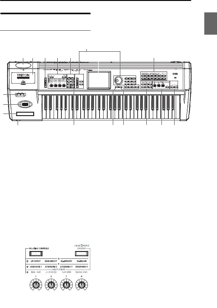
Front and rear panel |
|||||||||
|
Front panel |
|||||||||
|
8 |
|||||||||
|
16 |
17 |
4 |
5 |
6 |
9 |
12 |
|||
|
1 |
|||||||||
|
2 |
|||||||||
|
3 |
|||||||||
|
18 |
7 |
10 |
11 |
13 |
14 |
15 |
|||
|
1. [SW1] key, [SW2] key |
Use the [REALTIME CONTROLS] key to select either the |
||||||||
|
These keys are on/off switches, their function can be |
the A mode, B mode or VALVE FORCE functions for the |
||||||||
|
assigned in Program, Combination, Sequencer, Song Play, |
realtime controllers, and use knobs [1]–[4] to control the |
||||||||
|
and Sampling modes. When on, the key will light ( p.21). |
tone, effects, MIDI control changes and Valve Force in |
||||||||
|
realtime ( p.22, QS p.6). |
2. Joystick
Various program parameters and effect parameters will determine what is being controlled by the joystick. Move the joystick up/down and left/right (+Y, –Y, –X, +X) to vary the effect ( p.21).
3. Ribbon controller
Various program parameters and effect parameters will determine what is controlled by the ribbon controller. Slide your finger to the left or right on this ribbon controller to vary the effect ( p.21).
4. [VOLUME] slider
This adjusts the volume that is output from the AUDIO OUTPUT (MAIN) L/MONO, R jacks and the headphone jack.
5. REALTIME CONTROLS
[REALTIME CONTROLS] key
This key selects either A, B or Valve Force mode for the realtime controllers. The selected mode will light.
VALVE FORCE [ON/OFF] key
Switches the Valve Force function on/off. When on, this key will light.
[1] knob, [2] knob, [3] knob, [4] knob
In A mode, the function of each knob is fixed. [1] is the low pass filter cutoff frequency, [2] is the filter resonance level or the cutoff frequency of the high pass filter, [3] is the filter EG intensity, and [4] is the filter/amp release time.
In B mode, each knob will control the function that was assigned to it in the Program, Combination, Sequencer, Song Play, or Sampling modes.
The Valve Force functions of the knobs are fixed; knob [1] controls the input level to Valve Force, knob [2] controls the mix level of the Valve Force analog ultra-low boost circuit, knob [3] controls input gain to the vacuum tube, and knob [4] controls the output level from Valve Force.
 Depending on the sound you are using, you may hear noise if you turn the Valve Force knobs or edit Valve Force parameters while sound is being produced.
Introduction
Other Preset Media, etc Effect Global Song Play Sampling Sequencer Combination Program
3
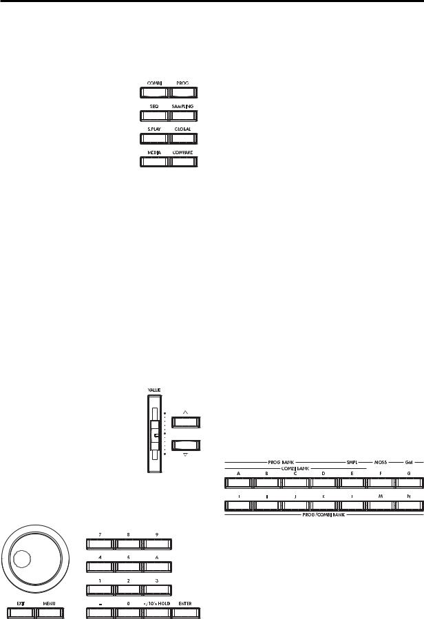
6. Mode keys
Use these keys to enter the desired mode.
When you press a key, the key will light, and you will enter the mode whose key you pressed ( p.10).
[COMBI] key
Combination mode will be selected.
[PROG] key
Program mode will be selected.
[SEQ] key
Sequencer mode will be selected.
[SAMPLING] key
Sampling mode will be selected.
[S.PLAY] key
Song Play mode will be selected.
[GLOBAL] key
Global mode will be selected.
[MEDIA] key
Media mode will be selected.
7. [COMPARE] key
Use this key when you wish to compare the sound of the program or combination that you are currently editing with the un-edited sound already in memory. You can also use this key to make “before and after” comparisons when recording or editing in Sequencer mode ( p.14).
8. VALUE controllers
The following VALUE controllers are used to set the value of the selected parameter ( p.14).
[VALUE] slider
Use this to modify the value of a parameter. This controller is convenient when you wish to make large changes in the value.
This slider can also be used as a modulation source.
[  ][
][  ] keys
These are used to increase or decrease the parameter value in steps of one. These keys are convenient for making fine parameter adjustments.
[VALUE] dial
Use this dial to modify the value of the parameter.
Numeric keys [0] – [9], [ENTER] key, [–] key [./10’s HOLD] key
Use these keys to numerically input a parameter value. Use numeric keys [0]–[9], the [–] key, and the [./10’s HOLD] key to enter the value, and press the [ENTER] key to confirm it. The [./10’s HOLD] key lets you input a value with a decimal point. The [–] key inverts the sign (+/–) of the parameter value.
The [./10’s HOLD] key is also used when you wish to hold the 10’s place while selecting programs or combinations.
By holding down the [ENTER] key while you press a numeric key [0]–[9] you can select up to ten page menu commands from the current page. In Program and Combination modes, you can hold down the [ENTER] key and press the SEQUENCER [REC/WRITE] key to turn on the Auto Song Setup function. ( p.58)
9. LCD screen
The TRITON Extreme features our exclusive TouchView graphic interface, based on a touch-panel LCD screen. By touching on objects that are shown in the LCD screen, you can select pages, tabs, and parameters, and set values ( p.8).
10. [EXIT] key
When in P (page) 1–9 of each mode, pressing the [EXIT] key will move to P (page) 0 of that mode.
When a dialog box is open, this key will cancel the settings made in the dialog box and close the dialog box (corresponds to the Cancel button). If a popup menu or page menu is open, pressing [EXIT] will close the menu.
11. [MENU] key
Use this key to move between pages. When you press the [MENU] key, a list of the pages in the mode will appear in the LCD screen. Press the desired page, and you will move to that page. You can also move to a page by holding down the [MENU] key and pressing the corresponding numeric key [0]–[9] ( p.9, 13).
12. BANK keys
These keys are used to switch the program/combination bank.
PROG BANK:
[A], [B], [C], [D], [E] (SMPL), [F] (MOSS), [G] (GM), [H], [I], [J], [K], [L], [M], [N]
COMBI BANK:
[A], [B], [C], [D], [E], [H], [I], [J], [K], [L], [M], [N]
In Program mode, these keys select the program bank.
In Combination mode, these keys select the combination bank. When assigning a program to the various timbres in a combination, then these keys will select the program bank. In this case, the key of the program bank selected for the timbre will light.
In Sequencer and Song Play modes when the edit cell (highlighted area) is located on the program name of a track, these keys will select the program bank, just as in Combination mode.
4
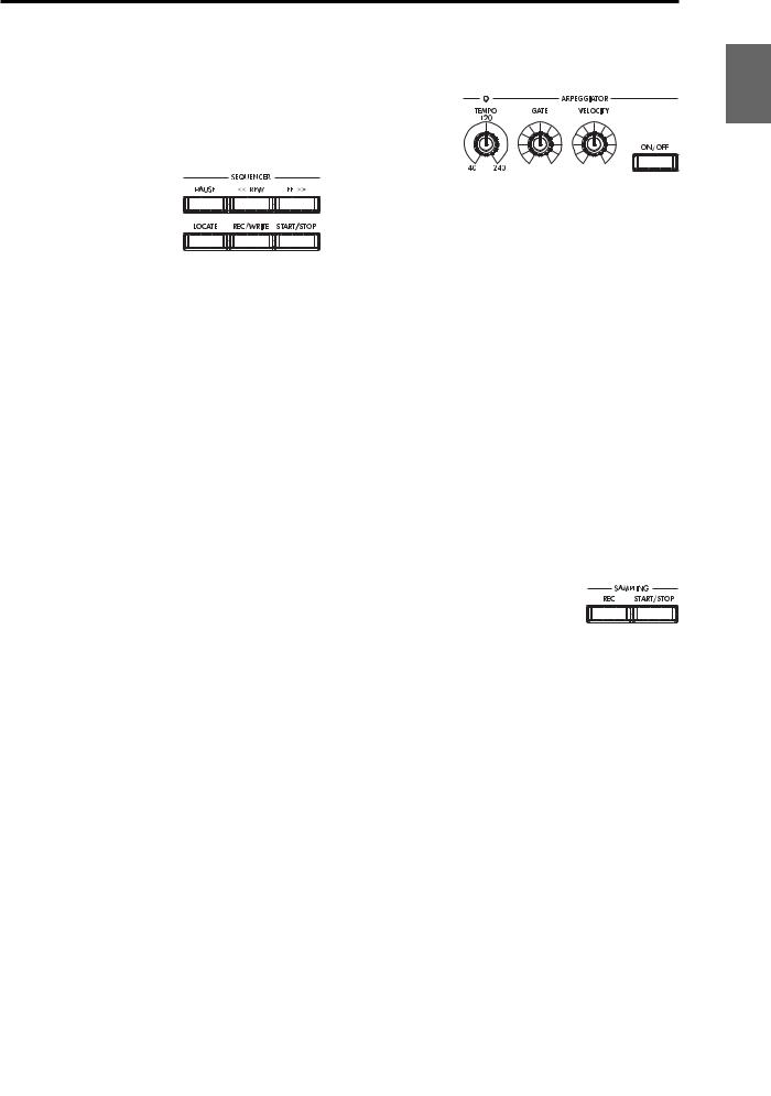
Each time you press the [G] key when selecting a program, the bank selection will step to the next GM(2) bank or GM drum bank in the following order: G, g(1), g(2)– g(8), g(9), g(d), G, g(1) etc …
The F bank can be only be selected in Program mode, and only if the EXB-MOSS option is installed.
13. SEQUENCER
[PAUSE] key
In Sequencer mode, this key pauses the playback of the song or cue list. In Song Play mode, this key pauses SMF playback. When paused, the key will light. Press [PAUSE] once again to resume playback; the key will turn off.
[<<REW] key
In Sequencer mode, this key will rewind the song or cue list. When you press and hold this key, the key will light, and the playback will rewind. (This key will not function during recording.)
[FF>>] key
In Sequencer mode, this key will fast-forward the song or cue list. When you press and hold this key, the key will light, and the playback will fast-forward. (This key will not function during recording.)
[LOCATE] key
In Sequencer mode, this key will advance or rewind the song or cuelist playback to a specified point. In Song Play mode, this key moves to the specified playback location within the SMF data.
SEQUENCER [REC/WRITE] key
In Sequencer mode, pressing this key will make the key light, and if you then press the SEQUENCER [START/ STOP] key, recording will begin ( p.43).
In Program, Combination and Global modes, pressing this key will open a dialog box, and if you then press the OK button, the edited contents will be written ( p.114, 116). In Program or Combination mode, you can hold down the [ENTER] key and press this key to turn on the Auto Song Setup function. ( p.58)
SEQUENCER [START/STOP] key
This is the start/stop key for song or cue list recording and playback in Sequencer mode, and SMF playback in Song Play mode.
During recording and playback, the key will blink at the current tempo.
These keys are also used to play an audio CD in the USBconnected CD-R/RW drive.
SEQUENCER [START/STOP] key : Play/Stop
|
[FF>>] key |
: Fast-forward |
|
[<<REW] key |
: Rewind |
|
[PAUSE] key |
: Pause |
|
[LOCATE] key |
: Move to the specified |
|
location |
14. ARPEGGIATOR
These knobs control the performance of the arpeggiator in realtime ( QS p.11).
[TEMPO] knob
This adjusts the base tempo of the arpeggiator and sequencer. The LED will blink at quarter-note intervals of the current tempo.
[GATE] knob
This adjusts the gate time (note duration) of the arpeggiated notes. At the center position (12 o’clock), the gate time will be the same as the “Gate” parameter of the arpeggiator. Rotating the knob toward the left will shorten the gate time, and rotating it toward the right will lengthen the gate time.
[VELOCITY] knob
This adjusts the velocity (playing strength) of the arpeggiated notes. At the center position (12 o’clock), the velocity will be the same as the “Velocity” parameter of the arpeggiator. Rotating the knob toward the left will decrease the velocity, and rotating it toward the right will increase the velocity.
[ON/OFF] key
This switches the Arpeggiator function on/off. When on, the key will light.
15. SAMPLING
SAMPLING [REC] key
In Sampling, Program, Combination, and Sequencer modes, pressing this key will make the key light, and when you continue by pressing the SAMPLING [START/ STOP] key, sampling will either begin or you will enter the sample-ready mode.
SAMPLING [START/STOP] key
In Sampling, Program, Combination, and Sequencer modes, pressing this key after pressing the SAMPLING [REC] key will either cause sampling to begin, or it will access the sample-ready mode.
In the Sampling P1: Sample Edit page, pressing this key will sound the selected sample.
This key is also used to play back a WAVE file from the media. This function can be used in the directory window of various Media mode pages, in the Media mode Make Audio CD page, and in the “Select Directory” page menu dialog box of the Program, Combination, Sequencer, and Sampling modes.
16. Valve cover
A 12AU7 (ECC82) vacuum tube (a.k.a. “valve”) is built-in.
 The valve cover may break if subjected to impact. Be particularly careful not to subject it to direct impact, since this may also break the vacuum tube. If the valve cover breaks, have it repaired immediately, since failing to do so may cause the vacuum tube or other parts to malfunction.
Introduction
Other Preset Media, etc Effect Global Song Play Sampling Sequencer Combination Program
5

17. Sample memory (RAM) slot cover
You can open this cover and install SIMM boards to expand the sample memory (RAM). A maximum of three 32 Mbyte SIMM boards can be installed as sample memory (RAM). ( PG p.321)
18. Headphone jack
A set of headphones can be connected here (stereo 1/4″ jack).
This allows stereo monitoring of the same signal as the OUTPUT L/MONO and R jacks.
Rear panel
1. AC power supply connector
Connect the included power supply cable here.
After connecting the power supply cable to the TRITON Extreme, connect the other end to an AC outlet ( p.16).
2. [POWER] switch
This switch turns the power on/off ( p.18).
3. AUDIO OUTPUT
Connect these outputs to the input jacks of your amp or mixer. In addition to the L/MONO and R main stereo audio outputs, the TRITON Extreme provides four individual audio outputs. The sound from each oscillator, drum, timbre/track, or insert effect can be freely routed to any output ( p.104–).
(MAIN) L/MONO, R
These are unbalanced phone jacks.
These are the main audio output jacks. By setting “BUS Select” to L/R, the output from an oscillator, an insert effect, an individual drum part, or the metronome can be output to the (MAIN) L/MONO and R jacks.
When making connections in stereo, use L/MONO and R. When making connections in mono, use the L/MONO jack.
(INDIVIDUAL) 1, 2, 3, 4
These are unbalanced phone jacks.
These are individual (independent) audio output jacks. By setting the “BUS Select” to 1, 2, 3(Tube), 4(Tube), 1/2, or 3/4(Tube), an oscillator, an insert effect, an individual drum part, or the metronome etc. can be assigned to be output from the (INDIVIDUAL) 1, 2, 3, 4, jacks.
The output from the 1, 2, 3, 4 jacks is not affected by the [VOLUME] slider.
4. AUDIO INPUT
These two audio inputs are used when recording a mono/ stereo sample from a mic or external audio source, or when applying the TRITON Extreme’s internal effects to an external audio source ( p.64, 107, 111).
The MIC/LINE level select switch ([MIC/LINE] switch) and the level adjustment knob ([LEVEL] knob) allow you to use a wide range of external audio sources, ranging from mic level to line level.
AUDIO INPUT 1/2 jacks
These are unbalanced phone jacks.
[LEVEL] knob
This adjusts the input level of the AUDIO INPUT 1/2 jacks.
[MIC/LINE] switch
This switches the input level of the AUDIO INPUT 1/2 jacks.
5. S/P DIF
OUT(MAIN) jack
This is an optical type S/P DIF format (IEC60958, EIAJ CP-1201) digital output jack.
It outputs a digital version of the same audio signal as the AUDIO OUTPUT (MAIN) L/MONO and R jacks, at sampling rates of 48 kHz.
6
![]()
2
1
Use an optical cable to connect this to the optical digital input jack of a DAT or MD, etc.
The [VOLUME] slider does not adjust the output level of this jack.
IN jack
This is an optical S/P DIF format (IEC 60958, EIAJ CP1201) digital input jack.
Digital audio at a sample rate of 48 kHz can be input here. Use an optical cable to connect this jack to the optical digital output jack of a DAT or other device.
6. USB
USB A connector (for connecting a CD-R/RW drive, etc.)
You can connect an external USB device to this connector. Use this connector to connect storage media such as a hard disk, MO, or CD-RW drive. ( PG p.325)
USB B connector (for connecting to a computer)
You can connect your computer to this connector. This lets you use your computer to access data on the TRITON Extreme’s CompactFlash (Microdrive) card. This connection also lets you send and receive MIDI data between the TRITON Extreme and your computer. ( PG p.325)
What is USB?
USB stands for Universal Serial Bus, and is an interface for transferring data between a computer, a keyboard and/or peripheral devices.
7. MIDI
MIDI THRU connector
Musical data and sound settings etc. that are received at the MIDI IN connector are re-transmitted without change from the MIDI THRU connector.
You can use this to connect multiple MIDI devices ( PG p.288).
MIDI OUT connector
Musical data and sound settings etc. are transmitted from this connector.
Use this to control another MIDI device connected via this port to the TRITON Extreme ( PG p.288).
MIDI IN connector
Musical data and sound settings etc. are received at this connector.
Use this to play the TRITON Extreme from another MIDI device connected to this port ( PG p.288).
|
6 |
7 |
8 |
9 |
10 |
11 |
||||||||||||||||||||||
8. DAMPER jack
An optional switch-type pedal such as the Korg DS-1H damper pedal can be connected here.
If a DS-1H is connected, it will function as a half-damper pedal. If another switch-type pedal is connected, it will function as a damper switch. In order to ensure that the pedal functions correctly, please adjust the polarity and the half-damper sensitivity ( PG p.157, 165).
9. ASSIGNABLE
SWITCH jack
An optional on/off foot switch such as the Korg PS-1 foot switch can be connected here.
In Global mode you can specify the function of this switch. For example, you can use it as a modulation controller, to select programs or combinations, to start/stop the sequencer, or to set the tap tempo. ( p.90).
PEDAL jack
An optional Korg EXP-2 or XVP-10 expression pedal can be connected here.
Its function can be assigned in Global mode, allowing you to use the pedal to control the volume etc. ( p.90)
10. [Contrast adjustment] knob
This adjusts the contrast of the LCD screen.
The optimal setting will depend on the height or angle from which you view the screen display, so please adjust as necessary.
11. CF card slot
You can insert a CompactFlash or Microdrive into this slot. The power must be off when inserting or removing media. For details on how to handle these types of media, refer to p.125.
Eject button
After making sure that the TRITON Extreme’s power is turned off, press this button to remove the media. If the media does not eject when you press this button, do not attempt to remove the media by force. Contact a nearby musical instrument dealer.
Introduction
Other Preset Media, etc Effect Global Song Play Sampling Sequencer Combination Program
7
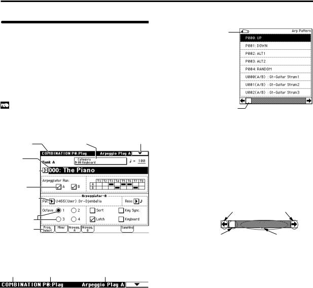
Names and functions of objects in the LCD screen
The TRITON Extreme uses Korg’s TouchView graphical user interface.
By touching objects displayed in the LCD screen, you can select pages, set parameter values, rename programs and combinations, write data, and perform many other operations.
References in the TRITON Extreme’s owner’s manual to the “… button” or “… tab” refer to objects displayed on the LCD screen. References to the “[…] key,” “[…] knob,” “[…] dial,” or “[…] slider” refer to controls on the front or rear panel of the TRITON Extreme.
|
a: Current page |
e: (category) Popup button |
i: Page menu button |
|
b: Edit cell |
||
|
d: Popup button (2) |
||
|
f: Check box |
||
|
c: Popup button (1) |
g:Radio buttons
h:Tab
a: Current page
This indicates the selected page within the current mode. From the left, this shows the mode name, page number, and page name.
|
Mode name |
Page number |
Page name |
b: Edit cell
When you press a parameter in the LCD screen, the parameter or parameter value will sometimes be highlighted (displayed in inverse video). This is called the edit cell, and the highlighted item will be subject to editing. The parameter value of the edit cell can be modified using the VALUE controllers ( p.14) or by using a popup button in the LCD screen. For parameters that accept a note number or a velocity value, you can also hold down the [ENTER] key and play a note on the keyboard to enter the note number or velocity value.
c: Popup button (1) 
When this button is pressed, a popup menu will appear, showing the parameter values that are available for selection.
To input the parameter value, press the desired value in the popup menu.
When a popup menu is displayed, operating a VALUE controller ( p.14) will close the popup menu. If the popup menu is unlocked ( “Pin”), it will close if you touch a location outside the popup menu.
* Popup menu
Pin
Scroll bar
Pin
This switches the popup menu display between locked and unlocked.
When locked, the pin will be shown closed, and the popup menu will remain displayed even after you press a parameter value. When unlocked, the pin will be shown opened, and the popup menu will close immediately when you press a parameter value.
Scroll bar
Use this when you wish to see parameter values that extend beyond what can be displayed in the screen at one time.
Press here to scroll to left or right.
|
Press here and slide to left |
Press here to scroll to |
|
or right to scroll to the |
the corresponding |
|
desired location. |
location. |
d: Popup button (2) 
When you press this button, a tabbed popup menu will appear, allowing you to perform the following selections.
•“Bank/Program Select,” “Bank/Combination Select”: Select programs or combinations by bank
•“Multisample Select”: Select a multisample for a program oscillator by category (ROM multisamples only)
•“Category/Effect Select”: Select an insert effect or master effect by category
To close the tabbed popup menu, press the OK button or Cancel button.
e: (Category) popup button
When you press this button, a tabbed popup menu will appear, allowing you to perform the following selections.
•“Category/Program Select,” “Category/Combination Select”: Select programs or combinations by category To close the tabbed popup menu, press the OK button or Cancel button.
8
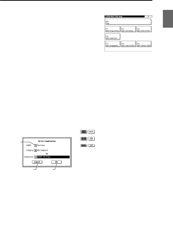
f: Check box
Each time you press a check box, a check mark will be added or removed.
When checked, the parameter will function; when unchecked, the parameter will not function.
g: Radio buttons
Press a radio button to select one value from two or more choices.
h: Tab
Press the tab to select a page.
i: Page menu button
When this button is pressed, a list of page menu commands will appear.
The page menu commands that appear will depend on the currently selected page.
You can also select up to ten page menu commands by holding down the [ENTER] key and pressing a numeric key [0]–[9].
The page menu will close when you press the LCD screen at a location other than the page menu, or when you press the [EXIT] key.
* Dialog box
The dialog box that appears will depend on the currently selected page menu command.
When selecting a program or combination number in a dialog box, use the VALUE controllers ( p.14) to input the number.
To execute, press the OK button. To cancel without executing, press the Cancel button. (The operation will occur when you press and release the button.) The dialog box will close. The [EXIT] key corresponds to the Cancel button, Done button, and Exit button.
Text edit button
 After some commands are executed, the previouslylocked page menu will be unlocked automatically, and the page menu will be closed.
* Text edit button
When you press this button, a text edit dialog box will appear.
Here you can rename text (such as the name of a program, combination, or song etc.) ( p.115).
* Page jump menu
In Combination, Program, Sequencer, Sampling, Song Play, or Global modes, you can press the front panel [MENU] key to view a list of the pages in that mode. (As a reminder, the page you were in before you pressed the [MENU] key will have its top right corner bent over.) By pressing one of the pages shown, you can move to that page. (You can also move to the corresponding page by pressing a numeric key [0]–[9].)
When you press the [EXIT] key, P0 will be displayed.
* Other objects
To modify the parameter value of an object shaped like a slider or knob, press it to move the edit cell to that object, and use the VALUE controllers to modify the value. In addition, there are also buttons similar to the OK button and Cancel button explained in “* dialog box” which execute an operation when they are pressed and released, such as the Done button, Copy button, and Insert button.
Toggle buttons
This type of button will change its function or switch on/ off each time it is pressed.
PLAY/MUTE/REC button in Sequencer and Song Play mode
SOLO ON/OFF button in Sequencer and Song Play mode
ON/OFF button for Insert Effect and Master Effect
Introduction
Other Preset Media, etc Effect Global Song Play Sampling Sequencer Combination Program
9
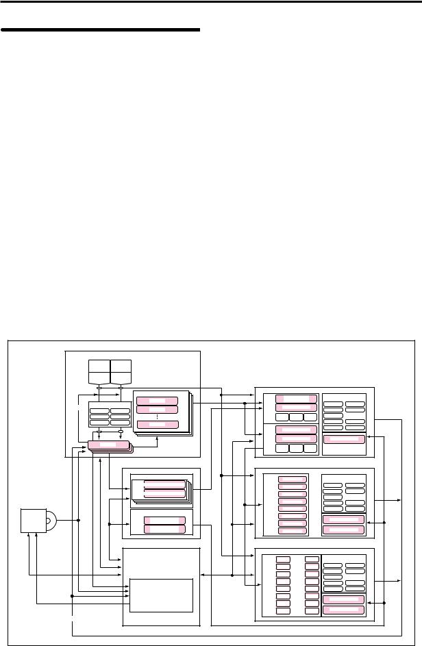
Overview of the TRITON
Extreme’s modes
The TRITON Extreme has a large number of functions that let you play and edit programs and combinations, record and play sequence data, record and play back samples, and manage data on media. The largest unit used to organize these functions is called a mode.
The TRITON Extreme has seven modes.
Program mode
•Select and play programs
You can choose programs from rewritable banks A–F and H–N which contain a total of 1,664 programs, and non-rewritable bank G (256 programs compatible with the GM2 standard, and nine drum programs).
(The 128 programs of bank F can be selected only if the EXB-MOSS option has been installed.)
•Sample or resample.
For example you can sample an external audio source while listening to the performance of the arpeggiator, or resample a performance you play using a program.
•Edit a program
Make settings for the oscillator, filter, amp, EG, LFO, effects, valve force, and arpeggiator.
The following multisamples are available for the oscillator.
•962 internal multisamples (160 Mbytes)
•Multisamples (RAM) that you sampled on the TRITON Extreme or loaded in from media (maximum of 96 Mbytes)
•Create drum programs using a drum kit (created in Global mode)
Combination mode
•Select and play combinations
A combination is a set of two or more programs (up to a maximum of eight), and allows you to produce complex sounds that could not be created by an individual program.
You can choose combinations from rewritable banks A–E and H–N which contain a total of 1,536 combinations.
•Sample or resample.
For example you can sample an external audio source while listening to the performance of the arpeggiators, or resample a performance you play using a combination.
•Edit a combination
Make settings for volume, pan, layer/split etc. for each timbre (program), and make settings for effects, valve force and the two arpeggiators.
SAMPLING MODE
AUDIO INPUT AUDIO INPUT 1 2
|
S/P DIF IN |
S/P DIF IN |
||||||
|
L |
R |
||||||
|
Multisample |
PROGRAM |
||||||
|
OSC 1 |
Insert / Master Effect / |
||||||
|
Multisample |
Multisample — H |
||||||
|
Sample |
Drum Kit |
Valve Force |
MFX 1 |
||||
|
Insert Effect / Valve Force |
Multisample — L |
IFX 1 |
|||||
|
Resampling |
Sample |
IFX 2 |
MFX 2 |
||||
|
IFX 1 |
IFX 4 |
||||||
|
IFX 2 |
IFX 5 |
PITCH1 FILTER1 |
AMP1 |
IFX 3 |
|||
|
IFX 3 |
Valve Force |
Sample |
IFX 4 |
MEQ |
|||
|
OSC 2 |
IFX 5 |
Valve Force |
|||||
|
Multisample — H |
|||||||
|
Multisample — L |
Arpeggiator |
||||||
|
Sample |
|||||||
|
Sample |
|||||||
|
Sample |
PITCH2 FILTER2 |
AMP2 |
|||||
|
Sample |
|
GLOBAL MODE |
COMBINATION |
|||||||||
|
DRUM KIT |
TIMBRE 1 |
PROGRAM |
Insert / Master Effect / |
|||||||
|
Key |
Valve Force |
|||||||||
|
Assign Drumsample / Sample — H |
TIMBRE 2 |
PROGRAM |
IFX 1 |
MFX 1 |
||||||
|
Drumsample / Sample — L |
TIMBRE 3 |
PROGRAM |
IFX 2 |
MFX 2 |
||||||
|
IFX 3 |
||||||||||
|
TIMBRE 4 |
PROGRAM |
IFX 4 |
MEQ |
|||||||
|
ARPEGGIATOR PATTERN |
TIMBRE 5 |
PROGRAM |
IFX 5 |
Valve Force |
||||||
|
CD-R/RW |
Ripping |
Preset Arpeggio |
TIMBRE 6 |
PROGRAM |
Arpeggiator — A |
|||||
|
Pattern: P0 — 4 |
TIMBRE 7 |
PROGRAM |
||||||||
|
User Arpeggio |
TIMBRE 8 |
PROGRAM |
Arpeggiator — B |
|||||||
|
Pattern: U00 — 506 |
||||||||||
|
CD-ROM |
Write Audio CD |
|||||||||
|
MEDIA MODE |
SEQUENCER / SONG PLAY |
|||||||||
|
TRACK 1 |
PROGRAM |
TRACK 9 |
PROGRAM |
Insert / Master Effect / |
||||||
|
Valve Force |
||||||||||
|
TRACK 2 |
PROGRAM |
TRACK 10 |
PROGRAM |
IFX 1 |
MFX 1 |
|||||
|
TRACK 3 |
PROGRAM |
TRACK 11 |
PROGRAM |
IFX 2 |
MFX 2 |
|||||
|
IFX 3 |
||||||||||
|
TRACK 4 |
PROGRAM |
TRACK 12 |
PROGRAM |
IFX 4 |
MEQ |
Only SEQ |
||||
|
Media |
TRACK 5 |
PROGRAM |
TRACK 13 |
PROGRAM |
IFX 5 |
Valve Force |
||||
|
TRACK 6 |
PROGRAM |
TRACK 14 |
PROGRAM |
Arpeggiator — A |
||||||
|
TRACK 7 |
PROGRAM |
TRACK 15 |
PROGRAM |
|||||||
|
TRACK 8 |
PROGRAM |
TRACK 16 |
PROGRAM |
Arpeggiator — B |
||||||
|
Resampling |
10

Sequencer mode
•Use the 16-track MIDI sequencer to record and play songs.
•Record onto the sixteen MIDI tracks individually or all sixteen tracks at once. Exclusive messages can also be recorded and edited.
•Perform sampling/resampling.
An external audio input source can be sampled in synchronization with the song playback. When doing so, you can automatically create a note event that will be used to trigger the resulting sample, letting you record an external audio source just as if you were recording onto an audio track. (This is called the “In-track Sampling” function.)
You can also resample the playback of a song. After resampling your song to media, you can then use Media mode to write the song to a CD-R/RW drive connected to the TRITON Extreme’s USB A connector, creating your own audio CD.
•Make effect and Valve Force settings for a song.
•You can record a performance that uses the arpeggiator(s) into a song or pattern.
•You can use a cue list to create an arrangement using individual songs for each verse, chorus, bridge, etc., and specify the number of repeats for each song.
•You can use a maximum of 20 cue lists, 200 songs, and 100 preset patterns. One song can use as many as 100 patterns.
•The TRITON Extreme can be used as a 16-part multitimbral tone generator.
•Perform using the RPPR (Realtime Pattern Play/ Recording) function, and adjust the various settings.
Song Play mode
•SMF (Standard MIDI File) data can be played back from a media, and you can perform along with the playback.
•Make effect and valve force settings for use in Song Play mode.
•The arpeggiator can be used while you play along with the SMF playback.
•SMF songs can be played back in succession.
You can use the jukebox function to playback songs in any specified order.
Sampling mode
•Sample external audio sources (i.e., record samples). Insert effects, valve force can be applied to the external input sound while you sample.
•Edit the waveform data you sampled or waveform data that you loaded in from media, and set loop points etc.
•Edit multisamples consisting of two or more samples.
•A multisample can be converted into a program, so that a multisample created in Sampling mode can be used in the Program, Combination, Sequencer, or Song Play modes.
•“Rip” (directly sample) digital data from an audio CD in a CD-R/RW drive connected to the USB A connector. You can also play back audio CDs.
Global mode
•Make settings that affect the entire TRITON Extreme, such as master tune and global MIDI channel.
•Create user drum kits (144 kits), user arpeggio patterns (507 patterns), and user scales (16 one-octave scales and 1 all-note scale).
•Create drum kits using the 1,171 internal drum samples (ROM). You can also use RAM samples that you created on the TRITON Extreme or loaded from media.
•Rename program and combination categories.
•Set the function of the assignable pedals and assignable switches.
•Transmit data dumps of MIDI exclusive data.
Media mode
•Data of each mode can be saved and loaded using CompactFlash or Microdrive media.
•Format the above types of media. You can also manage data by copying it, etc.
•Korg, AKAI, AIFF, and WAVE format sample data can be loaded. Sample data can also be saved in Korg format, or exported in AIFF or WAVE formats.
•Songs that you created in Sequencer mode can be saved in SMF format. SMF files can be loaded as Sequencer mode songs.
•You can use the Data Filer function (to save/load MIDI exclusive data).
•Edit Wave files.
•Specify the song order of Wave files and use a CD-R/ RW drive connected to the USB A connector to create an audio CD. You can also play back audio CDs.
•Use a computer connected to the USB B connector to manage (e.g., copy or delete) data on media inserted in the TRITON Extreme’s CF card slot. (USB storage mode)
Introduction
Other Preset Media, etc Effect Global Song Play Sampling Sequencer Combination Program
11

About polyphony
Tone generators and oscillators
Each oscillator in the TRITON Extreme is sounded by one of two Tone Generators.
Each tone generator is connected to the various PCM memories as shown in the diagram below.
Tone Generator 1
•ROM: Internal PCM ROM (32 Mbytes)
•RAM: User sample memory (16 Mbytes, expandable to a maximum of 96 Mbytes)
Tone Generator 2
•Piano:
•New1:
•New2:
•Best:
•OrchS:
•OrchB:
•Vint:
•Synth:
Internal PCM ROM (128 Mbytes)
ROM (Internal PCM ROM) 32 Mbytes
|
RAM |
96 Mbytes* |
|
(User sample memory) |
Piano (Internal PCM ROM) 16 Mbytes
|
New1 ( |
« |
) |
16 Mbytes |
|
|
New2 ( |
« |
) |
16 Mbytes |
|
|
Best |
( |
« |
) |
16 Mbytes |
|
OrchS ( |
« |
) |
16 Mbytes |
|
|
OrchB ( |
« |
) |
16 Mbytes |
|
|
Vint |
( |
« |
) |
16 Mbytes |
|
Synth ( |
« |
) |
16 Mbytes |
|
* = Expandable to a maximum. |
Total 128 Mbytes |
|
Factory settings is 16 Mbytes |
|
Tone Generator 1 |
Tone Generator 2 |
|
|
Maximum 60 oscillators |
Maximum 60 oscillators |
Total maximum 120 oscillators
Each tone generator is able to simultaneously sound up to 60 oscillators (i.e., to play the PCM data connected to that tone generator). Together, the two tone generators are able to sound up to 120 oscillators.
For example up to 60 oscillators can use the ROM, and up to 60 oscillators can use the Piano, making a total of 120 oscillators. However, you can’t play 61 or more oscillators from the ROM alone.
Number of voices in each mode
The maximum number of voices that can be played simultaneously will depend on the oscillator mode of the program.
•For a Single/Drum-mode program, 1 oscillator = 1 voice
•For a Double-mode program, 2 oscillators = 1 voice
Program mode
Single/Drums (“Oscillator Mode”)
Normally, 60 voices can be used.
However a maximum of 120 voices will be available if, for example, ROM or RAM is used for the High MS, and Piano–Synth is used for the Low MS, and you use velocity switching to play the two tone generators.
Double (“Oscillator Mode”)
Normally, 30 voices can be used.
However if OSC1 is sounded by one tone generator and OSC2 is sounded by the other tone generator (e.g., OSC1=ROM, OSC2=Piano–Synth), a maximum of 60 voices can be used. If OSC1 and OSC2 use one tone generator (e.g., OSC1=ROM, OSC2=ROM), then a maximum of 30 voices can be used.
This can also be increased by velocity switch and velocity zone settings.
Combination, Sequencer, and Song Play modes
Depending on the oscillator mode of the programs you are using, the maximum number will vary between 60 voices and 120 voices.
(Example)
For single-mode programs that use ROM or RAM, a total maximum of 60 voices
For single-mode programs that use Piano–Synth, a total maximum of 60 voices
Total 120 voices
For double-mode programs that use ROM or RAM, a total maximum of 30 voices
For double-mode programs that use Piano–Synth, a total maximum of 30 voices
Total 60 voices
Sampling mode
Tone generator 1 is always used in Sampling mode.
Mono samples/multisamples
60 voices.
Stereo samples/multisamples
30 voices.
12
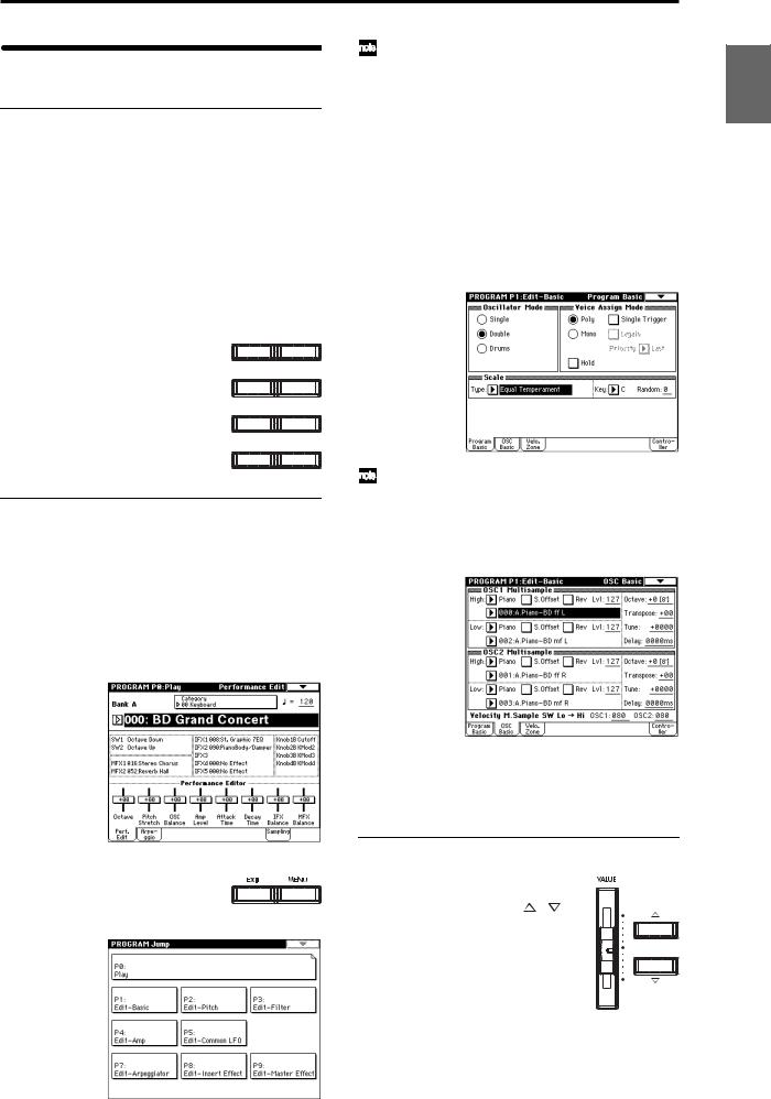
Basic operation
1. Selecting modes
 In order to use a particular function on the TRITON Extreme, you must first select the appropriate mode. Press one of the front panel mode keys ([COMBI] key
– [MEDIA] key) to enter the corresponding mode.
|
[COMBI] key: |
Combination mode |
|
[PROG] key: |
Program mode |
|
[SEQ] key: |
Sequencer mode |
|
[SAMPLING] key: |
Sampling mode |
|
[S.PLAY] key: |
Song Play mode |
|
[GLOBAL] key: |
Global mode |
|
[MEDIA] key: |
Media mode |
|
COMBI |
PROG |
|
SEQ |
SAMPLING |
|
S.PLAY |
GLOBAL |
|
MEDIA |
COMPARE |
2. Selecting pages
Each mode has a large number of parameters, which are organized into pages.
These are further subdivided by tabs into up to eight tab pages.
1Make sure that the desired mode is selected.
To select a mode, press the appropriate mode key ([COMBI] key – [MEDIA] key).
Here we will use Program mode as an example for our explanation. Press the [PROG] key.
2Press the [MENU] key.
The page jump menu will appear.
|
In Media mode there is only one page, so the page |
Introduction |
|
|
jump menu will not appear. |
||
|
3 In the LCD screen, press the desired page. |
||
|
You will jump to the selected page, and it will appear |
||
|
in the display. As an example here, press P1: Edit-Basic. |
||
|
• As a reminder, the page that was selected before you |
||
|
pressed the [MENU] key will have its top right corner |
||
|
bent over. |
||
|
• You can also jump to the corresponding page by |
||
|
pressing a numeric key [0]–[9]. (P0–P9 correspond to |
||
|
numeric keys [0]–[9].) |
Program |
|
|
• By holding down the [MENU] key and pressing a |
||
|
numeric key [0]–[9], you can jump directly to the |
||
|
corresponding page without displaying the page jump |
||
|
menu. |
||
|
Combination |
||
|
Sequencer |
||
|
4 Press one of the tabs located at the bottom of the |
Sampling |
|
|
When you press the [EXIT] key, you will return to P0 |
||
|
from any page. |
||
|
page. |
Play |
|
|
As an example here, press the OSC Basic tab which is |
||
|
the second from the left. |
||
|
Song |
||
|
Global |
||
|
• Some pages have no tabs. |
Effect |
|
|
5 To move to a page with a different ‘P’ number, press |
etc |
|
|
the [MENU] key and continue from step 2 of this |
||
|
procedure. |
Media, |
|
|
3. Setting a parameter |
||
|
The parameter value in the edit cell can |
Preset |
|
|
be set by using the front panel VALUE |
||
|
controllers ([VALUE] slider, [ ][ ] |
||
|
keys, [VALUE] dial, numeric keys [0]–[9], |
||
|
[–] key, [ENTER] key, and [./10’s HOLD] |
||
|
key). As necessary, you can also use the |
Other |
|
|
[BANK] keys and the [COMPARE] key. |
||
|
For some parameters, the value can be set |
||
|
by pressing a popup button to display |
||
|
the popup menu and then selecting a |
||
|
parameter value, or by holding down the [ENTER] key |
||
|
and playing a note on the keyboard to input a note num- |
||
|
ber or velocity value. |
13
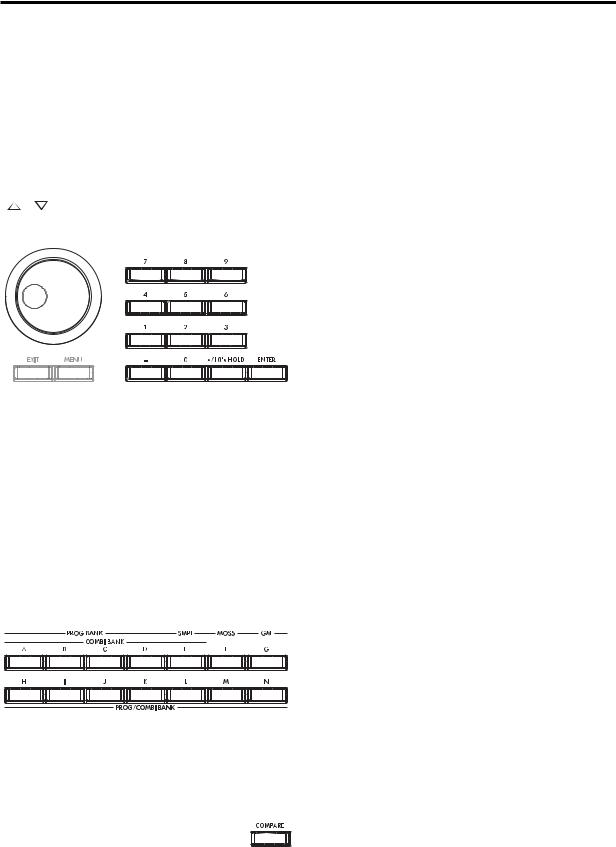
VALUE controllers
[VALUE] slider
Use this when you wish to make major changes in the value.
In Program mode and Combination mode, this slider can also be used as a control source for alternate modulation or dynamic modulation. (This is active in Program or Combination P0: Play when the “Program Select” or “Combination Select” (the large characters in the upper part of the LCD) is selected).
Use these when you wish to make small changes in the value.
[VALUE] dial
Use this when you wish to make large changes in a value.
Numeric keys [0]–[9], [ENTER] key, [–] key, [./10’s HOLD] key
Use these when you know the parameter value that you wish to input.
After using the numeric keys [0]–[9] to input a number, press the [ENTER] key to finalize the parameter value. Use the [–] key to enter negative numbers.
Use the [./10’s HOLD] key to enter a decimal point.
In Program and Combination mode P0: Play page other than the Sampling page, the [./10’s HOLD] key performs the 10’s Hold function. ( p.21, 32)
BANK [A]–[G], [H]–[N] keys
The BANK [A]–[G], [H]–[N] keys are used in Program mode to select the program bank and in Combination mode to select the combination bank. In combination, Sequencer and Song Play modes, these keys are used to select the bank of the program used by each timbre/track.
[COMPARE] key
Use this key when you wish to compare the edits you have made to a program or combination’s sound with the un-edited original (i.e., the sound that is written into memory).
When editing a program or combination, press this key. The LED will light, and the last-written settings for that program number or combination number will be recalled. When you press the [COMPARE] key once again, the LED will go dark and you will return to the settings that you were editing.
If you edit the settings that are recalled by pressing the [COMPARE] key (i.e., the settings that are written into memory), the LED will go dark, and it will not be possible to return to the previous edits by pressing the [COMPARE] key again.
In Sequencer mode, you can use the [COMPARE] key to make “before and after” comparisons immediately after using realtime recording or step recording to record a song, or after performing a track edit operation.
For example, this can be used effectively when realtimerecording a track for a song.
1 Realtime-record a MIDI track. (Take 1)
2 Once again, realtime-record on the same track. (Take 2)
3Press the [COMPARE] key. The LED will light, and take 1 will be recalled.
4Press the [COMPARE] key once again. The LED will go dark, and take 2 will be recalled.
5If at step 3 you once again realtime-record on the same track (take 3), the object of the Compare function will now be take 1. If at step 4 you once again real- time-record on the same track (take 3), the object of the Compare function will be take 2.
In this way, the Compare function lets you recall the previous recording or the previous state of event editing.
 The Compare function is not available Sampling, Song Play, Global, or Media modes.
Popup buttons and popup menus
You can press a popup button to access a popup menu, and then set parameter values ( p.8).
Keyboard input
When inputting a note number or a specific velocity as the value of a parameter, you can use the keyboard to input the setting. Hold down the [ENTER] key and play the note that you wish to enter as a value. The note number or velocity value will be input.
When the Global P5: Drum Kit page is displayed, you can hold down the [ENTER] key and play a note to recall the settings that have been assigned to that note.
In Sampling mode, you can hold down the [ENTER] key and play a note to recall the index that is assigned to that note.
14

Setup
Connections
 Connections must be made with the power turned off. Please be aware that careless operation may damage your speaker system or cause malfunctions.
3. Analog audio input connections
If a passive type guitar (a guitar without an internal preamp) is connected, it will not be possible to sample at an appropriate level due to the impedance mismatch. Such instruments must be connected via a preamp or effect unit.
Effect processor etc.
CD player,
analog record player, etc.
AUDIO OUTPUT/ 

AUX OUT etc.
Mic
5. Connecting pedals
|
8. Connections to MIDI equipment/computers |
DAMPER |
|
ASSIGNABLE |
|
|
SWITCH |
|
|
MIDI OUT |
MIDI cable
PEDAL
|
Power Switch |
MIDI IN |
AUDIO |
INPUT 1, 2 
|
AC power supply |
USB A B S/P DIF |
AUDIO OUTPUT |
||||||||
|
OUT IN |
(INDIVIDUAL) |
(MAIN) |
CF |
|||||||
|
1. Connecting the power |
9. Installing options |
4 |
3 |
2 |
1 |
R L/MONO |
||||
|
CompactFlash |
||||||||||
|
cable |
Microdrive card |
|||||||||
|
Power cable (Included) |
Option EXB-MOSS |
6. Inserting and |
||||||||
|
SIMM |
removing CF card |
|||||||||
|
to an AC outlet |
slot media |
|||||||||
|
USB cable |
||||||||||
|
DAT etc. DIGITAL IN |
||||||||||
|
CD-R/RW, hard disk, |
DIGITAL OUT |
|||||||||
|
4. Digital audio input/output |
||||||||||
|
removable disks etc. |
Computer |
|||||||||
|
7. Connecting a USB device |
connections |
INPUT |
PHONES |
|||||||
|
1 |
2 |
3 |
4 |
5 |
6 |
Monitor
OUTPUT
1 
 2
2 
 3
3 
 4
4 
 5
5 
 6
6 
 7–8
7–8 
 9–10
9–10 
 11–12
11–12 
 13–14
13–14
2. Analog audio output connections
|
Powered monitors, |
Mixer |
|
etc. |
Other Preset Media, etc Effect Global Song Play Sampling Sequencer Combination Program Setup
15
1. Connecting the power cable
1 Turn off the power of the TRITON Extreme.
2Plug the included power cable into the AC power supply connector located on the back of the TRITON Extreme.
3Connect the other end of the power cable to an AC outlet.
Use only the power cable that is included with the TRITON Extreme. Using another power cable may cause malfunctions.
 Make sure that your AC outlet is the correct voltage for your instrument.
2. Analog audio output connections
Connect a set of amplified monitor speakers or your audio system to the TRITON Extreme.
 If you play back the TRITON Extreme through your stereo audio system, be aware that high volumes may damage your speakers. Be careful not to raise the volume excessively.
 Connecting the AUDIO OUTPUT (MAIN) L/MONO, R, (INDIVIDUAL) 1, 2, 3, and 4 jacks to the INPUT jacks of your mixer or powered monitor system.
L/MONO and R are the main outputs. If you are outputting in stereo, make your connections using the (MAIN) L/MONO jack and the R jack. If you are outputting in mono, make your connection to the (MAIN) L/MONO jack.
The (INDIVIDUAL) 1, 2, 3, and 4 jacks are used to output specific sounds independently. For example, you can use these to apply an external effect to the snare sound of a drum kit.
When you are sampling, and want to hear the sounds played by the TRITON Extreme’s sequencer while you sample only the external audio source, send the source to (INDIVIDUAL) 1 and 2. If you want to monitor this sound, you can connect (INDIVIDUAL) 1 and 2 jacks to your mixer, and monitor the sound via your mixer.
Headphones
 If you are using headphones, connect them to the headphone jack of the TRITON Extreme.
The TRITON Extreme’s headphone jack will output the same signal as (MAIN) L/MONO and R.
If you are using (INDIVIDUAL) 1, 2, 3, and 4, connect these jacks to your mixer, and use the headphone jack of your mixer to monitor the sound.
3. Analog audio input connections
You can input external analog audio sources, and sample them or process them with the internal effects and output them from the OUTPUT jacks.
 Connect mics or the OUTPUT jacks of your external audio equipment to the AUDIO INPUT 1 and 2 jacks.
4. Digital audio input/output connections
Digital audio output
The same audio signal present at the TRITON Extreme’s AUDIO OUTPUT (MAIN) L/MONO and R jacks can be output in digital format to a DAT, MD, or digital multitrack recorder that can accept a digital audio input with a sample frequency of 48 kHz.
 Use an optical cable to connect the S/P DIF OUT (MAIN) jack to the optical digital input jack of your DAT, MD, or digital multitrack recorder.
The [VOLUME] slider does not affect the volume of this output jack.
Digital audio input
TRITON Extreme can accept a digital audio input from a DAT or other digital device that can output digital audio at a sampling frequency of 48 kHz. This signal can be input to the L and R channels, then sampled or processed by the internal effects and output from the OUTPUT jacks.
 Use an optical cable to connect the optical digital output jacks of your DAT etc. to the S/P DIF IN jack.
5. Connecting pedals
Foot pedal connections
A foot pedal can be used to control various synthesis and effect parameters.
Connect an optional expression pedal such as the Korg XVP-10 or EXP-2 to the rear panel ASSIGNABLE PEDAL jack.
The function controlled by the foot pedal is specified in Global: P2 “Foot Pedal Assign” ( p.90, PG p.165, 282)
Foot switch connections
A foot switch controls sostenuto, soft pedal on/off, arpeggiator on/off, to select programs or combinations, and to start/stop the sequencer and tap tempo etc.
Connect an optional foot switch such as the Korg PS-1 to the rear panel ASSIGNABLE SWITCH jack.
The function assigned to the foot switch and the polarity of the foot switch can be set in Global: P2 “Foot Switch Assign,” and “Foot Switch Polarity” ( p.90, PG p.165, 281)
Damper pedal connections
This pedal applies a piano style damper effect as you play. Connect an optional footswitch to the DAMPER jack of the TRITON Extreme. If a Korg DS-1H is connected, halfdamper effects can be produced.
The polarity of the pedal is set in Global P2: Controller “Damper Polarity” and the sensitivity is set in Global P0 “Half Damper Calibration.” ( PG p.157, 165)
16
![]()
6.Inserting and removing CF card slot media
You can insert a CompactFlash or Microdrive card into the CF card slot, and use it to save or load song data or sample data.
When using a Microdrive, you can save the sampled data directly to media.
The TRITON Extreme’s CF card slot does not support hot-plugging. You must turn off the power before inserting or removing CF card slot media. Turning off the TRITON Extreme to insert media into the CF slot will cause your unsaved sequence and sample data to be lost; so we suggest you always insert your media before you turn the TRITON Extreme on, in case you want to save any of the data you create.
Inserting media
1 Turn off the power of the TRITON Extreme.
2Make sure that the CF card slot eject button located on the rear panel is pressed inward.
If the eject button is in the outward position, press it in.
3Insert your CompactFlash or Microdrive card into the CF card slot.
Make sure that the card is oriented correctly; the label should be upward, and the connector end inserted first.
 CF card slot
Eject button
CompactFlash
Microdrive
4Push the card in until the media is inserted all the way into the slot.
5 Turn on the power.
To verify that the media was recognized correctly, check that the Media mode “Media Select” display shows CF (CompactFlash) or MD (Microdrive).
( p.119)
If the display indicates Unformatted, you will need to format the card. Newly purchased media or media that has been used by another device must also be formatted before you use it on the TRITON Extreme for the first time. For the formatting procedure, refer to p.119.
Removing media
1 Turn off the power of the TRITON Extreme.
2Press the CF card slot eject button located on the rear panel, and pull the button outward.
3Press the CF card slot eject button inward, and then pull the media out of the connector inside the slot.
4Remove the media from the slot.
Store the media correctly as described in the instructions included with the media.
7. Connecting a USB device
You can connect an external USB device such as a hard disk or CD-R/RW drive to the USB A connector, and transfer data to and from the device.
 Connect the TRITON Extreme’s USB A connector to the USB connector of your external USB device.
If you connect the TRITON Extreme’s USB B connector to your computer, you will be able to transfer data to and from your computer. You can also send and receive MIDI data to/from your sequencer software or similar application.
 Connect the TRITON Extreme’s USB B connector to the USB connector of your computer.
For details on connecting USB devices, refer to PG p.325.
8.Connections to MIDI equipment/ computers
Connections to MIDI equipment
The keyboard, controllers, and sequencer etc. of TRITON Extreme can be used to control an external MIDI tone generator. Conversely, another MIDI keyboard or sequencer can control the tone generator of TRITON Extreme to produce sound.
 Use MIDI cables to connect the MIDI connectors of TRITON Extreme with the MIDI connectors of your external device.
PG p.288 “MIDI applications – Connecting MIDI devices/computers”
Connections to a computer
Your performance on the TRITON Extreme, as well as controller and sequencer data, can be sent to a computer (connected via MIDI interface), and the tone generator of TRITON Extreme can be played from the computer.
 Use a MIDI interface to connect the MIDI connectors of TRITON Extreme to the MIDI connectors of your computer.
 Connect the TRITON Extreme’s USB B connector to the USB connector of your computer.
PG p.288 “MIDI applications – Connecting MIDI devices/computers”
 Some USB-MIDI interfaces may not be able to transmit or receive the TRITON Extreme’s MIDI exclusive messages.
9. Installing options
The functionality of the TRITON Extreme can be extended by installing option boards and/or sample memory. The following two types of options can be installed. For details on installation, refer to PG p.319.
•EXB-MOSS (DSP synthesizer board)
•DRAM SIMM (Memory boards for sample data)
Other Preset Media, etc Effect Global Song Play Sampling Sequencer Combination Program Setup
17
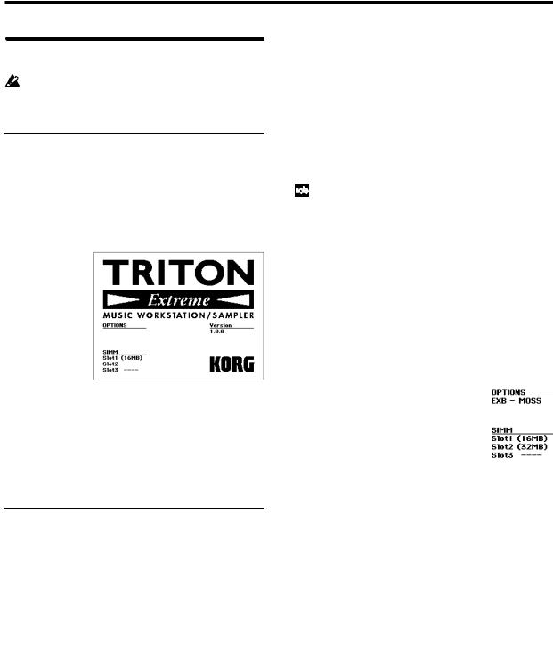
Turning the power on/off
Before you turn on the power, make sure that the desired connections have been made as described in “Connections” ( p.15).
1. Turning the power on
1Press the rear panel [POWER] switch to turn on the power.
The LCD screen will display the name of your model, and the software version.
(The following graphic shows the factory-set LCD screen. The version number is subject to change without notice.)
2 Turn on your powered monitors or stereo amp.
3Raise the TRITON Extreme’s [VOLUME] slider to an appropriate level, and adjust the volume of your powered monitors or stereo amp.
 You must turn off the power before inserting media into the CF card slot. The TRITON Extreme’s CF card slot does not support hot-plugging.
2. Turning the power off
1Set the front panel [VOLUME] slider and the volume of your powered monitor or stereo amp to zero.
2Turn off the power of your powered monitor or stereo amp.
3Press the TRITON Extreme’s [POWER] switch to turn off the power.
 Never turn off the power while data is being written into internal memory.
 If the power is turned off while processing is being performed, memory write operations will not be completed correctly. If this occurs, TRITON Extreme will automatically initialize its internal memory so that it will operate correctly. This is not a malfunction.
While data is being written, the LCD screen will indicate “Now writing into internal memory.” Data is written into internal memory by the following operations.
•Writing (updating) a Program, Combination, Global Setting, Drum Kits, or Arpeggio Patterns
•Loading Program, Combination, Global Setting, Drum Kit, or Arpeggio Patterns data in Media mode
•Receiving a MIDI data dump for Program, Combination, Global Setting, Drum Kit, or Arpeggio Patterns
•When using Sampling mode page menu commands (“Move Sample,” “Move MS,” “Convert To Program,” “Time Slice,” etc.) to simultaneously modify programs or drum kits.
•When sampling to RAM in Program, Combination, or Sequencer mode, if you simultaneously convert the sample to a program.
 Never turn off the power while the CompactFlash etc. media is being accessed. If you turn off the power while media is being accessed, the media may become unusable.
You can set the “Power On Mode” (Global P0: System Preference page) so that the mode and page that had been selected when you turned the power off will appear when the power is turned on. ( p.90)
Information displayed in the LCD screen when various options or SIMM modules are installed
The TRITON Extreme allows you to install separately sold options or sample memory (RAM) boards.
When the power is turned on, the type of installed options will be displayed. After installing an option, be sure to check this display to verify that the option was installed correctly. If the option is not displayed here even though it was installed, it was not installed correctly. Turn off the power and re-install the option. ( For details on installing an option, refer to PG p.319)
OPTIONS
EXB-MOSS: The EXB-MOSS option is installed.
SIMM
Slot 1…3 (** MB): Sample memory (RAM)’s are installed in SIMM slots 1–2. The capacity of each SIMM is shown in parentheses. When shipped from the factory, a 16 MB SIMM is installed in SIMM slot 1.
18
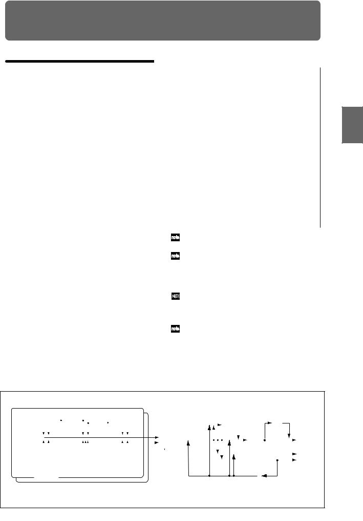
Playing and editing programs
(Program Mode)
Program structure
When the TRITON Extreme is shipped from the factory, it contains 1,344 programs (excluding the GM2 variation programs). You can create your own original programs by editing these factory-set programs, or by initializing a program and starting “from scratch.” You can also create programs using RAM multisamples that you have sampled or loaded in Media mode. In addition, you can play a program and resample your performance, or sample an external audio source while listening to the sound of a program.
Each of the rewritable banks A–E and H–N contain 128 programs (total 1,536). There are also non-rewritable bank G (GM2 capital programs), banks g(1)–g(9) (variation programs), and bank g(d) (drums). When shipped, banks A– D and H–N contain preloaded programs.
Program banks
|
Bank |
Prog. No. |
Explanation |
|
A…D, H…M |
000…127 |
Preloaded programs |
|
E |
000…127 |
User (initial) programs |
|
F |
000…127 |
MOSS programs |
|
G |
001…128 |
GM2 capital programs |
|
g(1)…g(9) |
( VNL) |
GM2 variation programs |
|
g(d) |
( VNL) |
GM2 drum programs |
|
N |
000…127 |
Preloaded programs, |
|
user (initial) programs |
||
For details on the factory-set programs, refer to “VNL.”
 You can select programs from bank F only if the EXBMOSS option is installed.
P0: Play is where you select and play programs, make simple adjustments using the Performance Editor, and adjust the arpeggiator settings.
In the P1: Edit-Basic–P9: Edit-Master Effect pages you can modify the sound by editing the various parameters of the program you selected in P0: Play.
Program structure and corresponding pages
Program mode page structure
|
Page |
Explanation |
|
|
P0: Play |
Select programs, use the Performance Editor to per- |
|
|
form easy editing, select and make settings for |
||
|
arpeggio patterns, make settings for sampling. |
||
|
P1: Edit-Basic |
Set basic program parameters such as oscillator |
|
|
and multisample. Set scale and controllers. |
||
|
P2: Edit-Pitch |
Settings related to the pitch, including the pitch EG. |
|
|
P3: Edit-Filter |
Settings related to the filter (tone), including the fil |
— |
|
ter EG. |
||
|
P4: Edit-Amp |
Settings related to the amplifier (volume), including |
|
|
amp EG and pan. |
||
|
P5: Edit- |
For each of the two LFO’s provided for each oscilla- |
|
|
Common |
tor, select the LFO type and speed, etc. (Settings in |
|
|
LFO |
the pitch, filter, and amp pages will determine how |
|
|
deeply the LFO that you specify here is applied.) |
||
|
P6: |
— |
|
|
P7: Edit- |
Settings for the arpeggiator. (Some of these are |
|
|
Arpeggiator |
shared with the arpeggiator settings of P0, and you |
|
|
may edit them in either location.) |
||
|
P8: Edit-Insert |
Select insert effects and make settings for them. |
|
|
Effect |
Specify the oscillator routing (send levels to the |
|
|
insert effects, master effects, and independent out- |
||
|
puts), make settings for Valve Force. |
||
|
P9: Edit-Master |
Select master effects and make settings for them. |
|
|
Effect |
Make settings for the master EQ and Valve Force. |
|
For details on how to access each mode and page, refer to “Basic operation” ( p.13).
Bank F is available only if the EXB-MOSS option is installed. The page structure and parameter structure of bank F programs are different than for the programs of other banks. Refer to the EXB-MOSS owner’s manual.
All transmission and reception of MIDI data in Program mode is performed on the global MIDI channel. The global MIDI channel is set in Global P1: MIDI “MIDI Channel.”
You can perform sampling/resampling in Program mode ( p.80, QS p.22). You can also apply the TRITON Extreme’s effects to an external audio input, for a wide range of possibilities. ( p.107, 111)
|
Controller |
||||||||||||||||||||||||||||||||||||||||||
|
Program Basic : P1 — 1 |
Setup: |
|||||||||||||||||||||||||||||||||||||||||
|
P1 — 4 |
||||||||||||||||||||||||||||||||||||||||||
|
Arpeggi- |
||||||||||||||||||||||||||||||||||||||||||
|
OSC1 LFO1 : P5 — 1 |
OSC1 LFO2 : P5 — 2 |
ator : P7 |
||||||||||||||||||||||||||||||||||||||||
|
Master |
Valve |
|||||||||||||||||||||||||||||||||||||||||
|
Effect |
Force |
|||||||||||||||||||||||||||||||||||||||||
|
Routing : P8-1 |
1, 2 : P9 |
: P9 |
||||||||||||||||||||||||||||||||||||||||
|
Placement: |
||||||||||||||||||||||||||||||||||||||||||
|
Final |
||||||||||||||||||||||||||||||||||||||||||
|
OSC Basic : P1 — 2,3 |
Filter1(A/B) : P3 — 1 |
Amp1 Level/Pan : P4 — 1 |
Insert |
Master |
AUDIO OUTPUT |
|||||||||||||||||||||||||||||||||||||
|
OSC1,2 |
Effect |
EQ : P9 |
L/MONO, R |
|||||||||||||||||||||||||||||||||||||||
|
1 … 5 : P8 |
||||||||||||||||||||||||||||||||||||||||||
|
OSC1 Pitch Mod. : P2 — 1 |
Filter1 Mod. : P3 — 2 |
Amp1 Mod. : P4 — 2 |
AUDIO OUTPUT |
|||||||||||||||||||||||||||||||||||||||
|
Insert Effect |
INDIVIDUAL |
|||||||||||||||||||||||||||||||||||||||||
|
Filter1 LFO Mod. : P3 — 3 |
Master Effect |
1, 2 |
||||||||||||||||||||||||||||||||||||||||
|
Individual Output |
3, 4 |
|||||||||||||||||||||||||||||||||||||||||
|
Filter1 EG : P3 — 4 |
Amp1 EG : P4 — 3 |
Placement: |
||||||||||||||||||||||||||||||||||||||||
|
Insert(Use Indiv.3/4 BUS) |
||||||||||||||||||||||||||||||||||||||||||
|
OSC 1 |
Valve |
|||||||||||||||||||||||||||||||||||||||||
|
Pitch EG : P2 — 3 |
Force |
|||||||||||||||||||||||||||||||||||||||||
|
: P9 |
||||||||||||||||||||||||||||||||||||||||||
|
OSC 2 |
||||||||||||||||||||||||||||||||||||||||||
 Oscillator / Pitch
 Filter
 Amplifier
  Effect
P1–1 and P2–2 etc. indicate the page tab screens used when editing on the TRITON Exterme.
Other Preset Media, etc Effect Global Song Play Sampling Sequencer Combination Program
19

|
Playing a program |
P0: Play |
Here you can select and play programs. You can use the Performance Editor to make simple edits, and also make settings for the arpeggiator, external audio input, and sampling.
Selecting a program
There are three ways to select a program. For the procedure, refer to the appropriate page.
•Using the controls of the TRITON Extreme
Selecting by bank/program number Selecting by program category Selecting by using 10’s Hold
•Using a connected switch
•Receiving MIDI program change messages
Selecting a program on the TRITON Extreme
Selecting by bank/program number
1Make sure that “Program Select” is selected.
If it is not selected, access the PROGRAM P0: Play page and press the “Program Select” area to highlight it.
Category popup button
Program  Select popup button
Program
Select
2Use the VALUE controllers to select the program number that you wish to play.
You can use the following methods to select a program.
•Turn the [VALUE] dial.
•Press the [ ] or [
 ] key.
•Use numeric keys [0]–[9] to specify the number, and press the [ENTER] key.
3Press a BANK [A]–[N] key to switch banks.
By switching banks you can access programs in different banks. (The key will light, and the selected bank will appear in the left side of the LCD screen.)
For example to select bank B, press the BANK [B] key. (The [B] key will light, and an indication of Bank B will appear in the upper left of the LCD screen.)
The [F] key is only available if the EXB-MOSS option is installed.
Each time the [G] key is pressed, it will advance to the next GM bank in the following order: G→g(1)→g(2)→g(3)→g(4)→(5)→g(6)→g(7)→g(8) →g(9)→g(d)→G … (The LED will light, and an indication of Bank G, g(1)–g(9), or g(d) will appear in the upper left of the LCD screen.)
Selecting by bank
You can select programs from a list organized by program bank.
1Press the “Program Select” popup button.
A tabbed “Bank/Program Select” popup menu will appear.
In the illustration above, bank G is selected. The center area shows the programs contained in that bank.
The Variation button will be displayed only when bank G is selected. Each time you press this button, the bank will change in the following order:
G→g(1)→g(2)…g(8)→g(9)→G…
2Press the tabs located to the left and right sides of the display to select a bank.
3Press one of the program names in the center area to select a program.
The selected program will be highlighted.
4When you are satisfied with the selected program, press the OK button to close the popup menu.
If you press the Cancel button, the selection you made here will be discarded, and you will return to the program that had been selected before you opened the popup menu.
Selecting by category
You can select programs from within a category, such as keyboard, organ, bass, and drums. When shipped from the factory, the preloaded programs are organized into sixteen categories.
1Press the Category popup button.
A tabbed “Category/Program Select” popup menu will appear.
In the illustration above, category 15: Drums is selected. The center area shows the programs contained in that category.
2Press the tabs located to the left and right sides of the display to select a different category.
The name of the selected category will be displayed in full in the upper right.
3Press one of the program names in the center area to select a program.
The selected program will be highlighted.
20
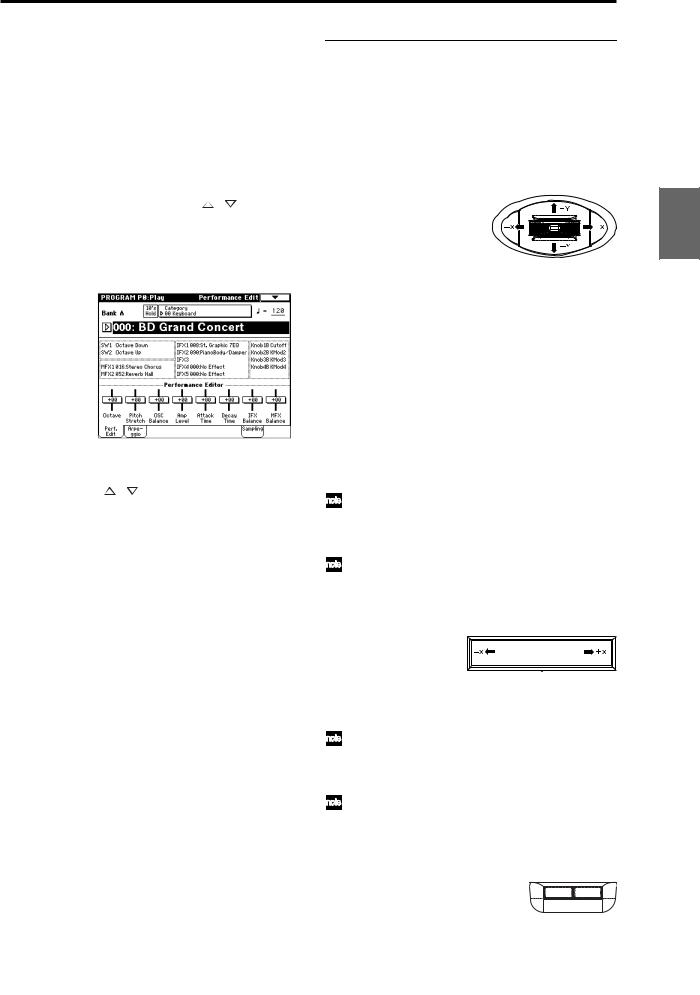
4When you are satisfied with the selected program, press the OK button to close the popup menu.
If you press the Cancel button, your selection will be discarded, and you will return to the program that had been selected when you opened the popup menu.
Using 10’s HOLD when selecting programs
If you press the [./10’s HOLD] key to turn on the 10’s Hold function (the LCD screen will indicate  ), the ten’s place of the program number will be fixed, and you will be able to switch programs simply by pressing a single numeric key. Each time you press a numeric key, the one’s place will change. You can also use the [ ][ ] keys to change the value of the ten’s place.
1Press the [./10’s HOLD] key to make the display indi-
cate  .
.
The ten’s place of the program number will be held (fixed).
2By pressing a numeric key [0]–[9], you can input the one’s place in a single action.
3 You can use the [ ][ ] keys to change the value of ten’s place.
4To cancel the 10’s HOLD function, press [./10’s HOLD] to erase the  display.
Using a footswitch to select programs
You can assign the Program Up/Down function to an on/ off type foot switch (such as the optional PS-1) connected to the rear panel ASSIGNABLE SWITCH jack, and use it to switch combinations. ( p.90)
Selecting programs from a MIDI device
MIDI program change messages can be transmitted from an external MIDI device, and received by TRITON Extreme to select programs.( PG p.290)
Using controllers to modify the sound
The TRITON Extreme provides various controllers – a joystick, the ribbon controller, the SW1 and SW2 switches, and the REALTIME CONTROL [1], [2], [3], [4] knobs – that let you modify the tone, pitch, volume, or effects in realtime while you play.
You can use these controllers to modify the sound while you are playing a program.
Joystick
JS(+X): Move the joystick toward the right to apply an effect.
Normally this is used to control the pitch (bend up).
JS(–X): Move the joystick toward the left to apply an effect.
Normally this is used to control the pitch (bend down).
JS(+Y): Move the joystick away from yourself to apply an effect.
Normally this is used to control the oscillator LFO (vibrato).
JS(–Y): Move the joystick toward yourself to apply an effect.
Normally this is used to control filter LFO (wah).
You can use the Lock function of [SW1] or [SW2] keys to hold the effect in the current position of the joystick. For the procedure, refer to “The lock function” on the following page.
You can use the joystick as a source for alternate modulation or effect dynamic modulation, to control program parameters or effect parameters.
Ribbon controller
0
Move your finger to the left and right on the ribbon controller to apply an effect.
Normally, this is used to control pitch, volume or filter etc.
You can use the Lock function of [SW1] or [SW2] keys to hold the effect even after you release your finger from the ribbon controller. For the procedure, refer to “The Lock function” on the following page.
You can use the ribbon controller as a source for alternate modulation or effect dynamic modulation, to control program parameters or effect parameters.
SW1, SW2
You can use these keys as sources for alternate modulation or effect dynamic modulation to control program parameters or effect parameters.
These switches can also be used to switch the octave, to turn portamento on/off, or to lock the position of the ribbon controller or after touch lock function.
Other Preset Media, etc Effect Global Song Play Sampling Sequencer Combination Program
21
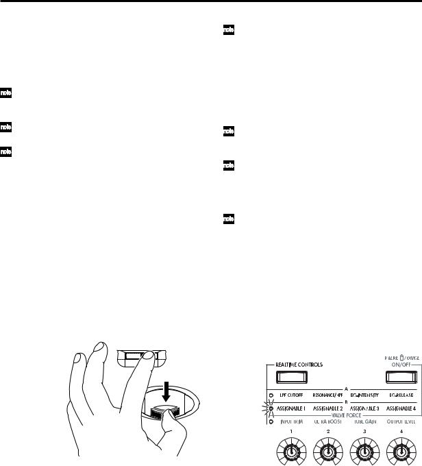
You can specify the way in which the [SW1] and [SW2] keys will operate: either Toggle, when the assigned function will be switched between on and off each time the key is pressed, or Momentary, when the assigned function will be active on only as long as you hold down the switch.
In Program mode, the function of the [SW1] and [SW2] keys can be checked in the P0: Play, Performance Edit page.
When you write a program or combination, the on/ off status of the [SW1] and [SW2] keys is saved.
For details on making these settings, refer to “Setting the function of [SW1] and [SW2]” ( p.129).
Using the Lock function (examples)
Joystick
1Select program bank J001: Acoustic Piano, and play the keyboard.
To select a program, make sure that you are in Program mode, and press the BANK [J] key, numeric key [1], and then the [ENTER] key.
2Move the joystick toward yourself (the –Y direction).
The modulation will deepen, and at the same time, resonance will be applied to give a unique character to the sound.
3While holding the joystick toward yourself, press the [SW2] switch (The [SW2] key will light).
The modulation effect at this point will be maintained. (Lock function)
4Release the joystick, and play the keyboard.
The modulation will stay the same as it was when the [SW2] key was pressed. Moving the joystick toward yourself will not affect the sound.
5Press the [SW2] key once again to release the Lock function.
Ribbon controller
Make sure that the J001: Acoustic Piano program is selected.
1 Press the [SW2] key. (The [SW2] key will light.)
2Touch the ribbon controller, and move your finger to left and right.
Movement in the +X direction will brighten the tone, and movement in the –X direction will darken the tone.
3Take your finger away from the ribbon controller.
The sound will remain as it was before you removed your finger. (Lock function)
4Press the [SW2] key once again to release the Lock function.
22
In the LCD screen, SW2 indicates JS–Y & Ribbon Lock. This means that the [SW2] key is assigned to control the Lock function for the joystick –Y direction and the ribbon controller ( PG p.279). The key will operate in Toggle mode.
If you move the joystick in the –Y direction, press the [SW2] key to turn on the Lock function, then operate the ribbon controller, and finally release both controllers, the sound you modified by the two controllers will be maintained.
In many programs and combinations, the [SW2] key is assigned to control the Lock function for the joystick –Y direction and the ribbon controller.
The Lock function can also be applied to aftertouch. If the [SW1] or [SW2] switch is assigned to After Touch Lock, the effect produced by pressing down on the keyboard can be held by turning on the [SW1] or [SW2] switch.
For details on the [SW1] and [SW2] switch functions, refer to PG p.279.
REALTIME CONTROLS [1], [2], [3], [4]
These knobs can be used to control the filter cutoff frequency and resonance, the amp and filter EG, volume, portamento time, pan, pitch LFO, or the send levels to the master effects, etc. You can also use these knobs to control the Valve Force parameters.
1Press the [REALTIME CONTROLS] key to switch the function of the realtime controllers.
Each time you press the key, A-mode, B-mode or Valve Force will be alternately selected, and the corresponding LED will light.
2 Rotate the desired knob to control the sound, etc.
For details about what is controlled, refer to QS p.6.
[VALUE] slider
When a program number is selected in Program P0: Play page, or when a combination number is selected in Combination mode page P0: Play page, you can use the [VALUE] slider as a source for alternate modulation or effect dynamic modulation, and control program parameters or effect parameters.
Keyboard
Velocity
The force with which you initially strike a note can apply an effect.
Normally this is used to control volume, or the speed or sensitivity of the EG.
After Touch
This effect can be applied by varying the pressure on a key that is already being held down.
Normally this is used to control volume, tone (cutoff frequency), or LFO sensitivity etc.

Note Number
Varying amounts of an effect will be applied depending on the position of the key on the keyboard.
Normally this is used to control volume, tone (cutoff frequency), LFO sensitivity, and EG sensitivity etc.
This can be used as a source for alternate modulation or effect dynamic modulation, to control program parameters or effect parameters.
Foot pedals/Switch
Damper Pedal
An optional switch-type damper pedal such as the Korg DS-1H can be connected to TRITON Extreme. If a DS-1H is connected, it will function as a half-damper pedal. The half-damper function cannot be controlled by other pedals.
Assignable Foot Switch
If an optional foot switch such as the Korg PS-1 is connected to the rear panel ASSIGNABLE SWITCH jack, an assigned function can be switched on/off using the foot switch.
The function of the foot switch is assigned in Global P2: Controller “Foot Switch Assign” ( p.90).
Assignable Foot Pedal
An optional expression pedal such as the Korg EXP-2 foot controller or Korg XVP-10 EXP/VOL pedal can be connected to the rear panel ASSIGNABLE PEDAL jack, and used to apply an effect.
The function of the foot pedal is assigned in Global P2: Controller “Foot Pedal Assign” ( p.90).
Easy program editing
Performance Edit (the Performance Edit tab)
You can use the eight Performance Editor sliders to make overall adjustments to the major parameters of Program P1–9.
For details on what is controlled, refer to QS p.6 or PG p.2.
REALTIME CONTROLS [1], [2], [3], [4]
For details on what is controlled, refer to QS p.6.
Easy arpeggiator editing
Arpeggio tab
Here you can select the arpeggio pattern, and make realtime adjustments to the arpeggio parameters while you perform.
ARPEGGIATOR [ON/OFF] key, [TEMPO] knob, [GATE] knob, [VELOCITY] knob
Use the ARPEGGIATOR [ON/OFF] key to turn the arpeggiator on/off.
The ARPEGGIATOR [TEMPO], [GATE], and [VELOCITY] knobs control the tempo, duration, and strength of the arpeggiated notes.
Program editing
You can edit the preloaded programs (banks A–D, H–N) that the TRITON Extreme is shipped with, or you can start with an initialized program (banks E, N) to create an original program.
The P0: Play page lets you perform basic editing, but more detailed editing can be done in the P1: Edit-Basic–P9: EditMaster Effect pages.
If you wish to save an edited program into internal memory, be sure to Write the program. ( p.114) You can write programs to the 1,536 program memory areas (internal memory) of banks A–E and H–N. You can also save and manage programs on various types of media. ( p.117)
The P1: Edit-Basic–P5: Edit Common LFO parameters are shared by oscillators 1 and 2, and can be copied using the page menu command “Copy Oscillator.” This command is useful when you want to set both oscillators to the same settings, or when you want to copy settings from a different program.
The three elements of sound
Sound can be broken down into three elements: pitch, tone, and volume.
On TRITON Extreme, these elements correspond to the Pitch, Filter, and Amplifier settings of a program. In other words you would adjust the Pitch settings to modify the pitch, the Filter settings to modify the tone, and the Amplifier settings to modify the volume.
In Oscillator (Oscillator: P1: Edit-Basic settings) you select the waveform multisample that determines the basic sound, and specify its pitch. This sound is then modified by the pitch settings (Pitch: P2: Edit-Pitch), filter settings (Filter: P3: Edit-Filter), and amp settings (Amplifier: P4: Edit-Amp) to create the basic sound of the program.
This basic sound can then be modified further by using the insert effects (P8: Edit-Insert Effect settings), master effects, master EQ, and Valve Force (P9: Edit-Master Effect settings) to apply finishing touches.
When arpeggiator settings (P7: Edit-Arpeggiator.) and controller settings (P1: Edit: Basic, Control Setup) are added to this, the final result is called a “program.”
The Compare function
When P1–P9 are selected, pressing the [COMPARE] key (the key will light) will recall the sound as it was written before you edited it.
Pressing [COMPARE] again (the light goes dark) returns you to the version you are editing.
If you edit while the [COMPARE] key is lit, the key will again go dark and your previous unsaved edits will be lost.
Other Preset Media, etc Effect Global Song Play Sampling Sequencer Combination Program
23

Oscillator settings P1: Edit-Basic
Basic settings for the oscillator are made in the P1: EditBasic page. The TRITON Extreme provides two oscillators, and for each oscillator you can select a basic waveform (“multisample”) and set the pitch.
The multisamples provided by the TRITON Extreme include waveforms for musical instruments such as pianos, as well as special waveforms unique to synthesizers. Multisamples reproduce the complex overtone structure and frequency characteristics that allow us to identify a sound as being “piano-like” or “guitar-like” etc..
Program Basic page
Oscillator Mode
This sets the mode of the oscillator. Single uses one oscillator and Double uses two oscillators. In the case of Single the maximum polyphony is 60 notes, and in the case of Double the maximum polyphony is 30 notes. If you wish to use a Drum Kit to create a drums program, select Drums. In the case of Drums, the polyphony is normally
60 notes.
Depending on the multisamples that are selected for each oscillator, the maximum polyphony can be up to
120 notes for Single, up to 60 notes for Double, and up to 120 notes for Drums. ( p.12)
Voice Assign Mode
Select whether the program will sound in Poly (polyphonically) or Mono (monophonically). If this is set to Poly, you will be able to play chords using the program. If this is set to Mono, only one note will sound even if you play a chord. Normally you will set this to Poly, but it is effective to use Mono when you are playing sounds such as a solo instrument, an analog-synth bass or a synth lead. Try switching between Poly and Mono, and listen to the results.
OSC Basic page
In this page you can select the multisample for each oscillator. The TRITON Extreme contains 962 different multisamples. ( VNL)
Data sampled on the TRITON Extreme can also be used as a multisample.
Selecting a multisample
The multisample will determine the basic character of the program.
 Use “High MS Bank” to select the multisample bank, and use “High Multisample” to select the multisample.
You can select preset multisamples if “High MS Bank” is set to other than RAM.
If “High MS Bank” is RAM, you can select multisamples that were sampled on the TRITON Extreme or loaded in from media. Select from 000–999 for “High multisample.”
Multisample bank
|
MS Bank |
Mbyte |
No. |
Explanation |
|
ROM |
32 |
000–424 |
TRITON Classic preset multisam- |
|
ples |
|||
|
RAM |
96 |
000–999 |
RAM multisamples (created in |
|
Sampling mode or loaded in Media |
|||
|
mode) |
|||
|
Piano |
16 |
000–003 |
Preset multisamples for stereo |
|
piano |
|||
|
New1 |
16 |
000–007 |
Preset multisamples for stereo |
|
piano and choir |
|||
|
New2 |
16 |
000–048 |
Preset multisamples for organ, |
|
solo brass, electric guitar, acous- |
|||
|
tic guitar, electric bass, acoustic |
|||
|
bass, etc. |
|||
|
Best |
16 |
000–046 |
Preset multisamples for electric |
|
piano, clavi, brass, woodwinds, |
|||
|
choir, drums, etc. |
|||
|
OrchS |
16 |
000–112 |
Preset multisamples for orchestral |
|
strings |
|||
|
OrchB |
16 |
000–079 |
Preset multisamples for orchestral |
|
brass, woodwinds, percussion, |
|||
|
and harp etc. |
|||
|
Vint |
16 |
000–157 |
Preset multisamples for vintage |
|
analog synths |
|||
|
Synth |
16 |
000–077 |
Preset multisamples for house and |
|
trance music |
|||
If “High MS Bank” is set to ROM, pressing the “High Multisample” popup button will display all internal ROM multisamples, organized into 15 categories. Use the tabs located at the left and right to select the desired category, and select a multisample from within that category.
High Multisample and Low Multisample
If you specify a High and Low multisample for an oscillator, either the High or the Low multisample will sound depending on the velocity of the note (i.e., the strength at which you play the keyboard). This function is called velocity multisample switching.
1Specify different multisamples for “High Multisample” and “Low Multisample.”
2Specify a velocity value for “Velocity M.Sample SW Lo→Hi.”
Notes played on the keyboard at a velocity less than the value you specify will sound the Low multisample; velocities at or above this velocity value will sound the High multisample.
For example if you set “Velocity M.Sample SW Lo→Hi” to 100, playing the keyboard softly will sound the “Low multisample,” and playing strongly will sound the “High multisample.”
24
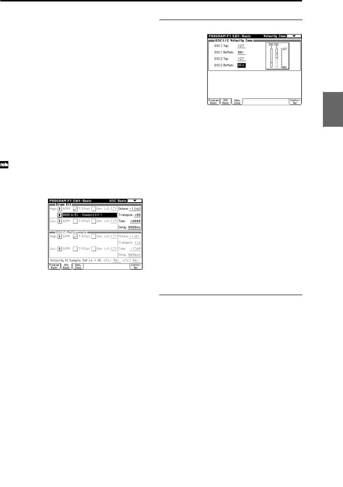
3Adjust the “Lvl” (Level) for High and Low multisamples to set their volume balance.
If you do not wish to use this function, set the “Velocity M.Sample SW Lo→ Hi” value to 001. Only the
High multisample will sound.
Rev (Reverse) check box
If this is checked, the multisample will be played backward. This can produce interesting results when used on sound-effects, etc. Normally you will not check this.
● When “Oscillator Mode” = Double
To use OSC2, set “Oscillator Mode” to Double in the Program Basic page.
In the same way as for OSC1, you can set High and Low multisamples for OSC2.
The playback pitch can be set independently. By using the same multisample with slightly different “Tune” settings, you can “detune” the oscillators to produce a richer sound.
It will be convenient to use the page menu command “Copy Oscillator” to make the oscillator settings match each other.
● When “Oscillator Mode” = Drums
In the Program Basic page, set “Oscillator Mode” to Drums. When this is set to Drums, you will be able to create a drum program.
This will select a drum kit instead of a multisample. TRITON Extreme provides 50 factory preset drum kits that are suitable for a wide variety of music. ( VNL)
Here you can only select a drum kit. To edit or create a drum kit, use Global P5: Drum Kit ( p.92).
The following multisamples or drum kits can be used for the oscillator.
•Preset multisamples (see the table on the preceding page)
•Multisamples that you sampled (RAM)
(Programs can be created from multisamples/samples that you sampled in Sampling mode etc. or loaded from media in Media mode.)
•Nine internal drum kits (ROM)
•144 user drum kits created in Global mode
(Drum samples can be freely assigned to each key to create a drum kit. For the sound of each key, you can make filter and amp settings, and specify routing to the effects and to the individual audio outputs.)
Velocity Zone page
Here you can specify the range of velocities for each oscillator. In the example shown above, the velocity ranges are as follows.
•OSC1 will sound at all velocity values.
•OSC2 will sound only on strongly played notes (64 and above).
•You can use Velocity Multisample Switching in addition to this parameter ( “High Multisample, Low
Multisample”). For this example, set “OSC1” in “Velocity M.Sample SW Lo→Hi” to 032 and “OSC2” to 096. The settings are shown as vertical lines in the velocity zone display.
In this example, the multisamples will sound over four levels.
Velocity values 001–031: sounds only the OSC1 Low multisample.
Velocity values 032–063: sounds only the OSC1 High multisample.
Velocity values 064–095: sounds the OSC1 High multisample and the OSC2 Low multisample.
Velocity values 096–127: sounds the OSC1 High multisample and the OSC2 High multisample.
Controller Setup page
For each program, this tab lets you make settings for the [SW1] and [SW2] key, and for the B-mode of REALTIME CONTROLS knobs [1]–[4] ( p.129, PG p.14, 279, 280)
Other Preset Media, etc Effect Global Song Play Sampling Sequencer Combination Program
25

|
Pitch settings |
P2: Edit-Pitch |
Here you can specify how the pitch of the multisample assigned to each oscillator will change. Pitch EG and LFO settings allow the pitch to varied over time. The OSC1 P.Mod page is valid when “Oscillator Mode” is set to Single or Drums.
OSC1 Pitch Mod. page
Pitch
The “JS (+X)” and “JS(–X)” settings specify the amount of pitch change (in semitones) that will occur when MIDI pitch bend messages are received or when the joystick is moved to left or right. A setting of +12 allows the pitch to be controlled a maximum of one octave upward; a setting of –12 allows the pitch to be controlled a maximum of one octave downward.
“Ribbon” specifies the amount of pitch change (in semitones) that will occur when MIDI control change (CC) #16 messages are received or when the ribbon controller of a TRITON Extreme or other MIDI-connected instrument is moved to left or right. With a setting of +12, the pitch will be raised one octave at the far right of the ribbon controller, and will be lowered by one octave at the far left of the ribbon controller.
Pitch EG
When the “Intensity” value is set to +12.00, the pitch EG specified in the Pitch EG page will produce a maximum of ±1 octave of pitch change.
Portamento
If “Enable” is checked, portamento will be applied. Portamento makes the pitch change smoothly when you play the next note before releasing the previous note. The “Time” parameter specifies the portamento time. As this value is increased, the pitch will change over a longer time. With a value of 000, there will be no portamento.
If Porta.SW CC#65 is assigned as the function of [SW1] or [SW2] key, the portamento effect can be switched on/off by [SW1] or [SW2] key.
LFO 1/2
An LFO can be used to cyclically modulate the pitch (a
“vibrato” effect).
“LFO 1/2 Intensity” sets the depth to which the LFO specified in P5: Edit-Common LFO will affect the pitch. With a setting of +12.00, vibrato will produce a maximum of ±1 octave of pitch change.
“JS+Y Int” specifies the amount of vibrato that the LFO will produce when the joystick is pushed away from yourself.
“Intensity (AMS Intensity)” specifies the depth of vibrato that will be applied by the LFO when an AMS (Alternate Modulation Source) is used. For example if “AMS (LFO1 AMS)” is set to After Touch and you set an appropriate value for “Intensity (AMS Intensity),” vibrato will be applied when you apply pressure to the keyboard or when MIDI aftertouch messages are received.
Pitch EG page
Here you can adjust the settings for the pitch EG. When you wish to create sound effects etc., set the pitch EG to make major changes in pitch over time.
To realistically simulate the slight change in pitch that occurs when a string is plucked or at the attack of a brass or vocal sound, you can use the EG to create a subtle change in pitch at the attack ( PG p.16).
● EG and LFO
By using an EG (envelope generator) to apply time-vary- ing change or by using an LFO (Low Frequency Oscillator) to apply cyclic change to pitch, filter, or amp, you can create changes in the pitch, tone, or volume.
EG (Envelope Generator)
TRITON Extreme provides a Pitch EG, Filter EG, and Amplifier EG, which produce time-varying changes in pitch, tone, and volume respectively.
|
note-on Attack Level |
note-off |
Break Level
|
Level |
||
|
Sustain Level |
Release Level |
|
|
Time |
||
|
Decay Time |
Slope Time |
Release Time |
|
Attack Time |
Start Level
LFO (Low Frequency Oscillator)
For each oscillator, TRITON Extreme provides two LFO’s that can be used to apply cyclical change in pitch, tone, and volume.
Examples of this are vibrato (cyclical change in pitch), wah (cyclical change in tone), and tremolo or auto-pan (cyclical change in volume).
26
![]()
|
Filter settings |
P3: Edit-Filter |
The filter allows you to diminish or emphasize specified frequency areas of the multisample selected for the oscillator.
The tone of the sound will depend significantly on the filter settings.
TRITON Extreme provides Filter 1 for OSC1 and Filter 2 for OSC2. For each of these filters, you can select from two types (Low Pass Resonance or Low Pass & High Pass). Filter 2 can be used if “Oscillator Mode” is set to Double.
|
Level |
Level |
Filter characteristics |
||||||||||||||||||||||
|
This area of |
||||||||||||||||||||||||
|
overtones will |
||||||||||||||||||||||||
|
be diminished |
||||||||||||||||||||||||
|
Filter |
Overtones after |
|||||||||||||||||||||||
|
Overtones included |
||||||||||||||||||||||||
|
in the original multisample |
passing through |
|||||||||||||||||||||||
|
the filter |
||||||||||||||||||||||||
|
Frequency (pitch) |
Frequency (pitch) |
Filter1 page
High pass filter
This type of filter allows the high frequency range to pass and cuts the low frequency range. Use this when you wish to make the sound thinner. However if the cutoff frequency (Frequency) is raised excessively high, the volume will become very low.
 High Pass
Level
 12dB/oct
 Frequency
Resonance
When “Resonance” is set to a higher value, the overtones in the region of the cutoff frequency will be boosted as shown in the diagram below, giving a distinctive character to the sound.
When resonance is applied
Low Pass
Level
Low resonance value 
 High resonance value
Filter1 Mod. page
Filter Type, Filter A, Filter B
Selects the type of filter, and specify the “Frequency” (cutoff frequency) and “Resonance” (resonance level).
•Low Pass Resonance (24 dB/oct low pass filter with resonance): Make settings for filter A.
•Low Pass & High Pass (12 dB/oct low pass filter and 12 dB/oct high pass filter in series connection): Make low pass filter settings in filter A, and high pass filter settings in filter B.
● Filter Type
Low pass filter
This is the most common type of filter, which allows the low frequency range to pass and cuts the high frequency range. When the overtones of the high range are cut, a bright sound will become darker (more mellow).
24 dB/oct and 12 dB/oct refer to the steepness of the cut. 24 dB/oct means that the gain will decrease 24 dB in one octave (i.e., as the frequency doubles). A 12 dB/oct filter would decrease the gain 12 dB in one octave. The 24 dB/ oct filter produces a steeper cut.
Low Pass
Level
12dB/oct
24dB/oct
 Frequency
Controllers and the filter EG can be used to modulate the filter cutoff frequency that was specified in the Filter1 page. By using a controller to vary the tone or by using an EG to create time-varying changes, you can add a rich variety of tonal change to the sound.
Keyboard Track
This varies the cutoff frequency according to the position of the key on the keyboard that you play.
•When “Ramp Low” is set to a positive (+) value, the cutoff frequency will rise as you play lower on the keyboard, making the sound brighter. When set to a negative (–) value, the cutoff frequency will fall as you play lower on the keyboard, making the sound darker.
•When “Ramp High” is set to a positive (+) value, the cutoff frequency will rise as you play higher on the keyboard, making the sound brighter. When set to a negative (–) value, the cutoff frequency will fall as you play higher on the keyboard, making the sound darker.
•“Intensity to A” and “Intensity to B” adjust the effect that keyboard tracking will have on filters A and B ( PG p.18).
Other Preset Media, etc Effect Global Song Play Sampling Sequencer Combination Program
27

Filter EG
Adjusts the effect produced by the filter EG, whose settings are made in the EG page.
•Use the “Velocity to A” and “Velocity to B” settings to specify the effect of velocity on the filter EG.
•Use the “Intensity to A” and “Intensity to B” settings to specify the depth of the filter EG.
•“Into A (AMS Int. to A)” and “Into B (AMS Int. to B)” adjust the effect that AMS will have on the filter EG depth.
These three settings will determine the depth of the tonal change produced by the filter EG.
Filter A/B Modulation
Set this when you wish to produce tonal change by using controllers etc. to vary the cutoff frequency.
Filter1 LFO Mod. page
Indicates settings that allow the LFO to produce cyclic changes in tone (a “wah” effect).
“Intensity to A (LFO Int. to A)” and “Intensity to B (LFO Int. to B)” specify by how much the LFO will change the tone.
“JS-Y Intensity to A” and “JS-Y Intensity to B” specify the depth of the wah effect that will be produced by the LFO when the joystick of TRITON Extreme is moved toward yourself, or when CC#2 is received.
“Intensity to A (LFO1 AMS Int.to A)” and “Intensity to B
(LFO1 AMS Int. to B)” specify the depth of the wah effect that will be produced by the LFO when “AMS (LFO1 AMS)” is used. For example if “AMS (LFO1 AMS)” is set to After Touch, applying pressure to the keyboard of the TRITON Extreme, will produce a wah effect.
Amplifier settings P4: Edit-Amp
These settings affect the volume. Here you can adjust the way in which the Amp EG and LFO produce time-varying and cyclic changes in volume, and how the controllers etc. will affect the volume.
Amp1 applies to OSC1, and Amp2 applies to OSC2. Amp2 can be used if “Oscillator Mode” is set to Double.
For example, the volume of a piano note begins at a high volume the instant you play the note, and then decreases gradually. The volume of an organ note remains constant as long as you continue pressing the key. The volume of a note on a violin or wind instrument can be varied during the note by the musician (i.e., by regulating the amount of pressure on the bow or the force of the breath).
|
Volume |
Piano |
Volume |
Organ |
|
Volume decays gradually |
Volume remains constant |
||
|
until note is released |
|||
|
Time |
Time |
Amp1 Level/Pan page
Filter1 EG page
Indicates settings for the filter EG, which controls timevariant changes in tone. Make settings for the EG here, and set the depth of its effect in the Filter1 Mod. page Filter EG parameter ( PG p.20).
● Filter EG and Amplifier EG
When the Filter EG changes the cutoff frequency, the tone will change. However depending on the volume changes produced by the Amplifier EG, this can be heard in different ways. For example by changing the speed at which the tone and volume begin (attack) or decay, you can significantly vary the character of the tonal change. It is a good idea to adjust the changes of both the Filter EG (tone) and the Amplifier EG (volume) as you proceed with editing. ( “Amp1 EG page”)
Amp Level
Adjusts the volume of the sound that has passed through the oscillator, filter, and amp.
Pan
Specifies the pan (stereo position) after the signal has passed through the oscillator, filter, and amp. Normally you will set this to C064. If “Oscillator Mode” is Double and you wish to create a sense of stereo, set the Amp1 Level/Pan page and Amp2 Level/Pan page parameter “Pan” to left and right for oscillators 1 and 2 respectively. With a setting of Random, the pan will change randomly each time you play a note on TRITON Extreme, producing an interesting effect.
AMS (Pan AMS), Intensity
“Intensity” specifies the depth of the panning effect that will occur when “AMS (Pan AMS)” is in use.
If you set “AMS (Pan AMS)” to Note Number, the pan will change according to the keyboard position at which you play a note on a TRITON Extreme. With a setting of LFO1 or 2, the sound will sweep from side to side (auto pan). Other settings allow you to move the oscillator pan by operating a controller.
Use DKit Setting
This is valid when “Oscillator Mode” is set to Drums. If this is checked, the pan location specified by the Drum Kit for each drum sound will be used. If this is unchecked, all drum sounds will sound at the same location. Preload and GM drum kits are set to stereo settings. Normally you will leave this checked.
28

Amp1 Mod. page
Keyboard Track
This lets you vary the volume relative to the position of the key you are playing on the keyboard.
•When “Ramp Low” has a positive (+) value, the volume will increase as you play lower on the keyboard. With a negative (–) value, the volume will decrease as you play lower on the keyboard.
•When “Ramp High” has a positive (+) value, the volume will increase as you play higher on the keyboard. With a negative (–) value, the volume will decrease as you play higher on the keyboard.
Amp Modulation
“Velocity Intensity” is used by most programs to decrease the volume of softly played notes and increase the volume of strongly played notes, and the Amp Modulation parameter adjusts the depth of this control. Normally you will set Amp Modulation to positive (+) values. As this setting is increased, there will be greater volume difference between softly played and strongly played notes.
LFO1/2
Specifies how the LFO’s will produce cyclic changes in volume (tremolo effect).
The volume will be affected by the LFO(s) for which you set an “LFO1 Intensity”, “LFO2 Intensity” value. “Intensity (AMS Intensity)” adjusts the depth by which the tremolo effect produced by the LFO will be affected when you assign an “AMS (LFO1 AMS, LFO2 AMS).” For example if you set “AMS” to JS-Y: #02, tremolo will be applied when you move the joystick of TRITON Extreme toward yourself, or when CC#02 is received.
Amp1 EG page
Here you can make settings for the amp EG, which changes the volume over time.
Every instrument has its own characteristic curve of volume change. This is part of what gives each instrument its identifiable character. Conversely, by applying a stringstype Amp EG curve to an organ-type multisample, you can produce a sound with a character unlike a typical organ.
Piano
Organ
Strings
LFO settings
P5: Edit-Common LFO
For each oscillator, you can use two LFO (Low Frequency Oscillator) units: LFO1 and LFO2. You are free to select the type of each LFO and set its speed.
The depth of the LFO1 and LFO2 that you specify here is adjusted by the settings of the P2: Edit-Pitch, P3: Edit-Fil- ter and P4: Edit-Amp pages.
OSC1 LFO1, OSC1 LFO2,
OSC2 LFO1, OSC2 LFO2
“Waveform” selects the type of LFO. You can choose from a variety of waveforms, including standard waveforms such as Triangle, Saw, Square, and Sine, as well as Step or Random PG waveforms that produce a sample-and- hold effect ( PG p.26).
You can create a wide variety of effects by adjusting the “Offset,” “Fade,” and “Delay” settings, and by changing the sign (+/–) of the “Intensity” setting in the P2: EditPitch, P3: Edit-Filter and P4: Edit-Amp pages. “Frequency” specifies the speed of the LFO.
Frequency Modulation
“AMS” can be used to vary the LFO speed. This lets you change the LFO speed by operating a controller, or by the EG or Keyboard Track settings.
Frequency MIDI/Tempo Sync.
If “MIDI/Tempo Sync” is checked, the “Frequency” setting will be ignored, and the LFO will synchronize to the tempo of the sequencer and arpeggiator. This lets you produce vibrato, wah, auto-pan, or tremolo effects that remain synchronized to the playback speed of the sequencer or arpeggiator, even if you adjust this playback speed.
Other Preset Media, etc Effect Global Song Play Sampling Sequencer Combination Program
29

Arpeggiator settings
P7: Edit-Arpeggiator
Here you can make arpeggiator settings ( p.94).
Insert Effect settings
P8: Edit-Insert Effect
Here you can select insert effects and make settings for them. You can also specify the oscillator routing (the signal sent to the insert effects, master effects, and independent outputs) ( p.104).
Master Effect and Valve Force settings P9: Edit-Master Effect
Here you can select master effects and make settings for them. The master EQ is also set here ( p.105, 109).
More about Alternate Modulation
Alternate Modulation is a type of modulation that can be used to control various aspects of the sound.
AMS (Alternate Modulation Source) refers to any of the numerous sources that can provide alternate modulation, and includes controllers that you operate physically such as the joystick and realtime controllers, incoming MIDI data, as well as modulators such as the EG or LFO.
Since TRITON Extreme allows you to apply modulation to a modulator, this type of control is referred to as “alternate modulation.”
Intensity is a parameter that sets the degree (speed or depth) to which AMS will control alternate modulation.
Combinations of modulations that are frequently used in synthesizer performance (such as using the joystick to vary the pitch) are also provided as special parameters separate from alternate modulation.
TRITON Extreme provides 29 types of alternate modulation.
In single mode you can use 29 alternate modulation destinations of 29 types, and in double mode you can use 55 alternate modulation destinations of 29 types.
There are 42 AMS sources. (However depending on the type of modulation, some sources cannot be selected.) For details on alternate modulation and AMS, refer to PG p.271.
Suggestions on using alternate modulation
When making settings for alternate modulation, think of the effect that you wish to produce, what type of modulation will be necessary to produce that effect, and what parameter of the oscillator, filter, or amplifier needs to be controlled. Then select a source (“AMS”) and set the “Intensity.” If you proceed logically in this way, you will achieve the desired effect.
For example if you want to “control a guitar-like sound so that it appears to be approaching feedback when the joystick is moved away,” you will make settings so that the joystick controls filter modulation or the resonance level.
Auto Song Setup function
This function automatically applies the settings of the current program to a song.
If inspiration for a phrase or song strikes you while you’re playing a program or combination, you can use this function to start recording immediately.
Hold down the [ENTER] key and press the SEQUENCER [REC/WRITE] key. The “Setup to Record” dialog box will open and ask “Are you sure?”. Press “OK”. You will automatically enter Sequencer mode, and will be in the recordready state. Press the [START/STOP] key to start the sequencer and begin recording.
30

Playing and editing combinations
(Combination Mode)
Combination structure
When the TRITON Extreme is shipped from the factory, it contains 1,280 combinations. You can create your own original combinations by editing these factory-set combinations, or by initializing a combination and starting “from scratch.”
You can play a combination and resample your performance, or sample an external audio source while listening to the sound of a combination.
Each of the rewritable banks A–E and H–N contain 128 combinations (total 1,536). When shipped, banks A–D and H–M contain preloaded combinations.
Combination banks
|
Bank |
Combi. No. |
Explanation |
|
A…D, H…M |
000…127 |
Preloaded combinations |
|
E |
000…127 |
User (initial) combinations |
|
EXB-MOSS combinations |
||
|
N |
000…127 |
User (initial) combinations |
For details on the factory-set combinations, refer to “VNL.”
P0: Play is where you select and play combinations. Here you can also make changes to the contents of each timbre, adjust the volume and pan, and make simple adjustments to the arpeggiator settings.
In the P1: Edit-Prog./Mixer–P9: Edit-Master FX pages you can modify the sound by editing the various parameters of the combination you selected in P0: Play.
Combination mode page structure
|
Page |
Explanation |
|
P0: Play |
Select a combination; select a program for |
|
each timbre; set the status, pan, and level; |
|
|
select and set the arpeggio pattern, make set- |
|
|
tings for sampling. |
|
|
P1: Edit-program/ |
Select a program for each timbre, and set pan |
|
Mixer |
and level. (These are common to the parame- |
|
ters in P0, and can be edited from either |
|
|
page.) |
|
|
P2: Edit-Trk Param |
Set various parameters for each timbre, such |
|
as MIDI, OSC, Pitch etc. |
|
|
P3: Edit-MIDI Filter |
MIDI transmission/reception filter settings for |
|
each timbre. |
|
|
P4: Edit-Zone/Ctrl |
Key zone and velocity zone settings for each |
|
timbre. Make controller settings. If the sepa- |
|
|
rately sold EXB-MOSS option is installed, set |
|
|
related parameters. |
|
|
P5: |
— |
|
P6: |
— |
|
P7: Edit- |
Arpeggiator settings. (These are common to |
|
Arpeggiator |
the parameters in P0, and can be edited from |
|
either page.) |
|
|
P8: Edit-Insert FX |
Select insertion effects and make settings. |
|
Specify the timbre routing (send levels to the |
|
|
insertion effects, master effects, and indepen- |
|
|
dent outputs). |
|
|
P9: Edit-Master FX |
Select master effects and make settings. |
|
Make settings for the master EQ and Valve |
|
|
Force. |
|
For details on how to access each mode and page, refer to “Basic operation” ( p.13).
If the EXB-MOSS option is installed, bank F programs will be available for you to select as a timbre in the combination. For details on the parameters of bank F programs, refer to the EXB-MOSS owner’s manual.
You can perform sampling/resampling in Combination mode ( p.80). You can also apply the TRITON Extreme’s effects to an external audio input, for a wide range of possibilities. ( p.107, 111)
Combination structure and corresponding pages
|
Controller |
||||||||||||||||||||||||||
|
Setup : |
||||||||||||||||||||||||||
|
P4- 4 |
||||||||||||||||||||||||||
|
Timbre1 |
Parameters |
Arpeggi- |
||||||||||||||||||||||||
|
Program |
ator : P7 |
|||||||||||||||||||||||||
|
Master |
||||||||||||||||||||||||||
|
Routing : P8-1 |
Effect |
Valve |
||||||||||||||||||||||||
|
1, 2 : P9 |
||||||||||||||||||||||||||
|
Timbre2 |
Parameters |
Force |
||||||||||||||||||||||||
|
: P9 |
||||||||||||||||||||||||||
|
Program |
||||||||||||||||||||||||||
|
Placement: |
||||||||||||||||||||||||||
|
Final |
||||||||||||||||||||||||||
|
Insert |
Master |
AUDIO OUTPUT |
||||||||||||||||||||||||
|
Timbre3 |
Effect |
EQ : P9 |
L/MONO, R |
|||||||||||||||||||||||
|
Parameters |
1 … 5 : P8 |
|||||||||||||||||||||||||
|
Program |
Timbre |
AUDIO OUTPUT |
||||||||||||||||||||||||
|
INDIVIDUAL |
||||||||||||||||||||||||||
|
1, 2 |
||||||||||||||||||||||||||
|
Timbre4 |
Parameters |
Insert Effect |
3, 4 |
|||||||||||||||||||||||
|
Master Effect |
Placement: |
|||||||||||||||||||||||||
|
Program |
Individual Outputs |
|||||||||||||||||||||||||
|
Insert (Use Indiv.3/4 BUS) |
||||||||||||||||||||||||||
|
Valve |
||||||||||||||||||||||||||
|
Force |
||||||||||||||||||||||||||
|
: P9 |
Timbre8 Parameters
Program
P1–1 and P2–2 etc. indicate the page tab screens used when editing on the TRITON Exterme.
Other Preset Media, etc Effect Global Song Play Sampling Sequencer Combination Program
31

Playing a combination P0: Play
Here you can select and play combinations. You can select the program for each timbre 1–8 and set its status, pan, and level. You can also make settings for the arpeggiator, external audio input, and sampling.
Selecting a combination
You can select a combination in any of the following three ways.
•From the TRITON Extreme
Selecting by bank/combination number Selecting by combination category Selecting by using 10’s Hold
•From a connected foot switch
•By receiving MIDI program changes
Selecting a combination on the TRITON Extreme
Selecting by bank/combination number
1Make sure that “Combination Select” is selected.
If it is not, select the COMBINATION P0: Play page and press “Combination Select” to highlight it.
Category popup button
Combination  Select popup button
Combination
Select
Bank/Program 
(Program Select)
Status
2Use the VALUE controllers to select the combination number that you want to play.
You can use any of the following methods.
•Turn the [VALUE] dial.
•Use the [ ][
][ ] keys.
•Use numeric keys [0]–[9] to specify a number, and press the [ENTER] key.
3Press a BANK [A]–[E] or [H]–[N] key to select a bank.
By switching banks you can select combinations from other banks. (The key will light, and the upper left of the LCD screen will indicate the selected bank.)
For example to select bank [B], press the BANK [B] key. (The [B] key lights, and the upper left of the LCD screen indicates Bank B.)
Selecting a combination by bank
When you press the “Combination Select” popup button, a list of the combinations in each bank will appear, allowing you to choose one of these combinations. ( Refer to the corresponding example for programs on p.20.)
Selecting a combination by category
When you press the Category popup button, a list of combination categories such as keyboard, organ, bass, or drums will appear, allowing you to select a combination from a specified category. With the factory settings, the combinations are organized into sixteen categories. (Refer to the corresponding example for programs on p.20.)
Using 10’s HOLD when selecting a combination
When you press the [./10’s HOLD] key to turn on the 10’s HOLD function (the LCD screen will indicate  ), the ten’s digit of the combination number will be held, and you will able to switch combinations simply by pressing a single numeric key. In this case only the one’s place of the number will change. You can use the [
 ][
][ ] keys to switch the ten’s place. ( Refer to the corresponding example for programs on p.21.)
Selecting a combination using a footswitch
You can assign the Combination Up/Down function to an on/off type foot switch (such as the optional PS-1) connected to the rear panel ASSIGNABLE SWITCH jack, and use it to switch combinations. ( p.90)
Selecting a combination from an external MIDI device
You can transmit a MIDI program change message from an external MIDI device to the TRITON Extreme to switch combinations. ( PG p.290)
For details on the factory-set combinations, refer to the VNL.
Using controllers to modify the sound
You can use the joystick, ribbon controller, SW1, SW2, Realtime Controls [1]–[4], [VALUE] slider, keyboard, and a foot pedal/switch to control the sound.
Refer to the corresponding explanation for programs on p.21.
Easy combination editing
Selecting a program for each timbre 1–8 (Program Select tab)
Switching the program assigned to each timbre 1–8 will change the sound of the combination.
There are three ways to switch programs. For details on each procedure, refer to the appropriate page of explanations.
•Selecting a program from the TRITON Extreme by bank/program number
by program category
•Selecting a program by receiving a MIDI program change
MIDI program changes cannot switch programs for a Timbre whose “Status” is set to other than INT.
For details on the factory-set program names, refer to the VNL.
Status
This specifies the status of MIDI and the internal tone generator for each timbre 1–8. Normally, you will set this to INT if you want the TRITON Extreme’s internal tone generator to sound. Set this to Off for timbres you are not using. If the status is set to Off, EXT, or EX2, that timbre will not sound. The EXT and EX2 settings allow the timbre to control a connected external MIDI device. ( QS p.8, PG p.38)
Mixer tab
Here you can adjust the pan and level for each timbre 1–8. ( QS p.9, PG p.40)
32

Easy arpeggiator editing
Arpeggio Play A/Arpeggio Play B tabs
•You can switch arpeggiators A and B on/off independently.
To turn both arpeggiators on/off, use the ARPEGGIATOR [ON/OFF] key.
The arpeggiator will operate only on timbres to which arpeggiator A or B is assigned.
•The ARPEGGIATOR [TEMPO], [GATE], and [VELOCITY] knobs control the tempo, duration, and strength of the arpeggiated notes. ( QS p.11)
Combination editing
You can edit the preloaded combinations (banks A–D, H– M) with which the TRITON Extreme is shipped, or start with an initialized combination (banks E, N) to create your own original combination.
You can perform simple editing even in the P0: Play page, but the P1: Edit-Program/Mixer–P9: Edit-Master FX pages let you perform more detailed editing.
Original programs using sample waveforms/multisamples you sampled on the TRITON Extreme (or loaded into memory via Media mode) can also be used in a combination.
If a program being edited in Program mode is used in a combination, it will sound according to the settings being edited.
If you wish to save an edited combination in internal memory, you must write it. ( p.114)
You can write combinations to the 1,536 combination memory areas (internal memory) of banks A–E and H–N. You can also save and manage combinations on various types of media. ( p.117)
Suggestions for editing procedure
First use P1: Edit-Program/Mixer to select the program for each timbre, and then use P4: Edit-Zone/Ctrl to specify the range in which each program will sound (layer, split, velocity switch, etc.). Then adjust the volume of each timbre, and set various other parameters.
To add finishing touches to the sound, you can assign insert effect settings (in P8: Edit-Insert FX) and master effect, master EQ and Valve Force settings (in P9: EditMaster FX) that are different from the effect settings of Program mode. In addition, you can make arpeggiator settings (in P7: Edit-Arp.) and controller settings (in P4: Edit-Zone/Ctrl) to create the finished combination.
By using the page menu command “Solo Selected Timbre”, you can listen to the selected timbre only. This is a convenient way to audition the individual sounds of timbres that are layered. ( PG p.39)
Layer, split, and velocity switch
Within a combination, you can use key position and velocity to determine which program will sound.
The programs assigned to each timbre can sound in three ways: as part of a layer, a split, or a velocity switch. A combination can be set to use any one of these methods, or to use two or more of these methods.
Other Preset Media, etc Effect Global Song Play Sampling Sequencer Combination Program
33

Layer
Layer refers to settings which cause two or more programs to sound simultaneously when a note is played.
Program A
Program B
Layer:
Two or more programs sound simultaneously.
Split
Split refers to settings which cause different programs to sound on different areas of the keyboard.
Split:
Different programs will sound in different areas of the keyboard.
Velocity switch
Velocity Switch refers to settings which cause different programs to sound depending on the velocity (keyboard playing dynamics).
|
Program B |
Strong |
Keyboard playing |
|
|
Program A |
Soft |
dynamics |
|
Velocity Switch:
Keyboard playing dynamics (velocity) switches between different programs.
On TRITON Extreme, you can use a different program for each of up to eight timbres, and combine two or more of the above methods to create even more complex setups.
|
Program A |
||||
|
Program B |
Program D |
Strong |
Keyboard playing |
|
|
Program C |
Soft |
dynamics |
||
Example:
B and C/D are split. In the lower keyboard range, A and B are layered. In the higher keyboard range, C and D are switched by velocity and layered with A.
As an additional possibility, you can set the slope for a key zone or velocity zone so that the volume diminishes gradually. This lets you change a split into a keyboard crossfade, or a velocity switch into a velocity crossfade.
|
Program A |
Program B |
Keyboard X-Fade (keyboard |
|
|
crossfade): |
|||
|
As you play from low notes |
|||
|
to high notes, the volume of |
|||
|
A will fade out, and the |
|||
|
volume of B will fade in. |
The Compare function
When one of the P1–P9 pages is selected, you can press the [COMPARE] key (the key will light) to recall the sound that was last written before editing. As you are editing a combi, you can use the [COMPARE] key to listen to the previously saved version (as it was before you began editing). Pressing [COMPARE] again (the light goes dark) returns you to the version you are editing.
If you continue editing when the [COMPARE] key is lit, the key will go dark, and the current setting will now be the sound that is recalled when the [COMPARE] key is dark.
Timbre 1–8 program, pan and volume P1: Edit-Program/Mixer
Here you can assign programs to each timbre 1–8, and set the pan and volume for each one.
These settings can also be made in the Program Select and Mixer pages of P0: Play.
Edit-Program/Mixer page
Category, Program Select (Bank/Program)
Assigns a program to each timbre.
When the “Bank/Timbre Program” select menu is displayed, you can select programs by bank.
When the “Category/Timbre Program” select menu is displayed, you can select programs from the 16 categories. ( p.32)
You can also use the BANK [A]–[N] keys to select the bank of the program.
If you wish to select programs by receiving MIDI program changes, do so in P0: Play.
Pan
Specifies the panning (stereo position) for each timbre. A setting of C064 will reproduce the oscillator pan setting of the program. Adjusting this parameter will move the sound to left or right while preserving the pan relationship between the oscillators. A setting of L001 is far left, and R127 is far right.
Volume
Adjusts the volume of each timbre.
Create the overall sound by adjusting the volume balance between timbres. The “Volume” setting is an important aspect of creating the sound, and this setting will have a significant effect on the overall impression produced by the Combination.
34

|
Settings for status, MIDI channel, |
OSC page |
|
and pitch parameters |
|
|
P2: Edit-Trk Param |
|
|
MIDI Ch page |
Status
Here you can specify the MIDI status of the internal tone generator assigned to each timbre. Normally when playing the internal tone generator of TRITON Extreme, you will set this to INT. Set this to Off for timbres that you are not using. With settings of Off, EXT, or EX2, TRITON Extreme will not sound. With settings of EXT or EX2, you can control an external tone generator connected via MIDI. ( PG p.38, 43)
MIDI Channel
Timbres that you wish to play from TRITON Extreme’s keyboard must be set to the global MIDI channel. Your playing on the keyboard is transmitted on the global MIDI channel, and will sound any timbre that matches this channel. Normally you will set this to Gch. When this is set to Gch, the MIDI channel of the timbre will always match the global MIDI channel, even if you change the global MIDI channel.
On some preloaded combinations that use the arpeggiator, timbres assigned to the arpeggiator may not have a “Status” of INT and “MIDI Ch” of Gch.
The reason for this is that these settings are for timbres that sound only when the arpeggiator is on. This is a very useful technique for creating combinations that use the arpeggiator. Refer to “Arpeggiator settings in Combination and Sequencer modes” ( p.96, PG p.49), and study the relationship between arpeggiator assignments, “Status,” and “MIDI Channel.”
Bank Select (when status=EX2)
This setting is valid when “Status” is set to EX2. It specifies that Bank Select messages will be transmitted from TRITON Extreme.
Force OSC Mode
Normally you will set this to PRG (the oscillator will play as set by the program settings).
If you wish to force a polyphonic program to sound monophonically in this combination, without re-writing the program itself, set this either to MN (Mono) or LGT (Legato). Conversely, set this to Poly if you wish to force a monophonic program to play polyphonically ( PG p.43).
OSC Select
Normally you will set this to BTH (Both).
If the timbre is using a program whose “Oscillator Mode” is Double, and you want only OSC1 or OSC2 (not both) to sound, set this to OSC1 (only OSC1 will sound) or OSC2 (only OSC2 will sound).
Portamento
Normally you will set this to PRG.
If you want to override the portamento setting specified in the program assigned to the timbre to be forced off, set this parameter to Off. Conversely, if you want to force the portamento to be on, or to change the portamento time, set this to a value of 001–127 to specify the portamento time.
Pitch page
Transpose, Detune (BPM Adjust)
These parameters adjust the pitch of the timbre.
•In a layer-type combination, you can set two or more timbres to the same program, and create a richer sound by using “Transpose” to shift their pitch apart by an octave or by using “Detune” to create a slight difference in pitch between the two.
•In split-type combinations, you can use “Transpose” to shift the pitch (in semitone units) of the programs specified for each key zone.
•If you wish to change the playback pitch of a drum program, use “Detune.” If you change the “Transpose” setting, the relationship between notes and drum sounds will change.
Other Preset Media, etc Effect Global Song Play Sampling Sequencer Combination Program
35

●Adjusting the BPM of multisamples or samples created in Sampling mode
If a timbre’s program uses multisamples or samples that you created in Sampling mode (or loaded in Media mode) at a specific BPM value, you can use the page menu command “Detune BPM Adjust” to call up a new BPM value. This changes the BPM by adjusting the playback pitch. ( PG p.44)
Other page
Delay [ms]
Specifies the amount of time before the program assigned to each timbre will sound. Specifies the time from when you play the keyboard until the program will sound.
If you select KeyOff for this parameter, the timbre will sound when the note is released.
Use Program’s Scale, Scale
Specifies the scale for each timbre. If you check “Use Program’s Scale,” the scale specified by the program will be used. Timbres for which this is not checked will use the Scale setting.
MIDI filter settings
P3: Edit-MIDI Filter
For each MIDI Filter item, you can specify whether or not the corresponding MIDI message will be transmitted and received. The checked items will be transmitted and received.
MIDI filter does not turn the function itself on/off, but specifies whether or not that MIDI message will be transmitted and received. For example if portamento is on, portamento will be applied to the sound of TRITON Extreme even if “Portamento SW CC#65” is unchecked.
For example if you selected a bass program for timbre 1 and a piano program for timbre 2 to create a split-type combination, you could make the following settings so that pressing the connected damper pedal would apply the damper effect only to the piano program of timbre 2.
 Set the P3: Edit-MIDI Filter-1 “Enable Damper” parameter
Timbre 1 “Enable Damper”: unchecked
Timbre 2 “Enable Damper”: checked
Layer, split, and velocity switch settings/Controller settings P4: Edit-Zone/Ctrl
Key Zone page (Key zone settings)
Indicates settings such as layer, split, and keyboard crossfade.
Specifies the range of notes that will be sounded by each timbre. Each area that sounds a timbre is referred to as a Key Zone. By setting key zones, you can create a combination in which different programs sound in different areas of the keyboard.
By combining key zones specified for each timbre, you can create layered or split combinations.
The upper and lower limits for the key zone of each timbre are set by the “Top Key” and “Bottom Key” respectively.
For example in the following diagram, timbres 1–3 are set to create a layered and split combination. This is specified by the key zone settings.
Timbres 2 and 3 create a layer. Timbre 1 and timbres 2/3 are split between the B3 and C4 note numbers.
|
Timbre 1 |
Piano |
|
|
Timbre 2 |
Brass |
|
|
Timbre 3 |
Strings |
|
|
C–1 |
B3 C4 |
G9 |
As an example here, we will explain how to create a combination like the one shown above.
1In the P0: Play, Program Select page or the P1: EditProgram/Mixer page, use the “Program Select” area to select the program that will be used for each timbre 1–3.
Select a piano program for timbre 1. Select a brass program for timbre 2. Select a strings program for timbre 3.
2In the MIDI Ch page of P2: Edit-Trk Param, set “Status” to INT for all the timbres that you wish to use, and set “MIDI Channel” to either Gch or to match the global MIDI channel (a “G” will be displayed after the channel number).
3In the Key Zone page of P4: Edit-Zone/Ctrl, set “Top Key” and “Bottom Key.”
Set timbre 1 to a “Top Key” of G9 and a “Bottom Key” of C4.
Set timbres 2 and 3 to a “Top Key” of B3 and a “Bottom Key” of C–1.
36
![]()
|
You can also enter these values by holding down the |
Set timbre 1 to a “Top Velocity” of 127 and a “Bottom |
|
|
[ENTER] key and playing a note on the keyboard. |
Velocity” of |
64. |
|
Set timbre 2 to a “Top Velocity” of 63 and a “Bottom |
||
|
Velocity” of |
1. |
Key Zone Slope
Here you can specify the range of keys over which the original volume will be reached, starting at the top key and bottom key.
In the example above, you could set the “Bottom Key” of timbre 1 to G3, and set the “Top Key” of timbre 2 to G4, so that these two timbres overlap. Next if you set the “Bottom Slope” of timbre 1 to 12, and set the “Top Slope” of timbre 2 to 12 the sound will change gradually, instead of changing suddenly between B3 and C4.
Vel Zone page (Velocity zone settings)
Here you can make settings for velocity switching and velocity crossfading.
For each timbre, you can specify a range of velocities for which it will sound. The range of velocities for which a timbre will sound is called a Velocity Zone. By setting a velocity zone, you can set up a timbre which will be sounded only by notes played within a certain range of velocities, and not by notes played outside this Velocity Zone.
By combining timbres that have differing velocity zone settings, you can create velocity switched combinations.
The upper and lower limits of the velocity zone of each timbre are determined by the “Top Velocity” and “Bottom Velocity” respectively.
The following diagram shows an example of a velocity switched combination in velocity will switch between timbres 1 and 2 to play different programs. Such combinations are created by setting the velocity zone.
|
Timbre 1 |
Brass |
127 |
||
|
64 |
Velocity |
|||
|
Timbre 2 |
Strings |
63 |
switch |
|
|
1 |
||||
As an example, we will explain how to create a combination like the one shown above.
1In the P0: Play, Program Select page or the P1: EditProgram/Mixer, Prog page, use the “Program Select” area to select the program that will be used for each timbre 1 and 2.
Select a brass program for timbre 1. Select a strings program for timbre 2.
2In the MIDI Ch page of P2: Edit-Trk Param, set “Status” to INT for all the timbres that you wish to use, and set “MIDI Channel” to either Gch or to match the global MIDI channel (a “G” will be displayed after the channel number).
3In P4: Edit-Zone/Ctrl, Vel Zone page, set the “Top Velocity” and “Bottom Velocity.”
Velocity Zone Slope
Here you can specify the range of values over which the original volume will be reached, starting from the top velocity and bottom velocity.
In the case of the above example, you could set the velocity zones of the two timbres so that they partially overlap, and set the “Top Slope” and “Bottom Slope” so that the sound changes gradually, instead of changing suddenly between velocity values of 63 and 64.
Control page (Controller settings)
For each combination, you can specify the functions of the B-mode functions of REALTIME CONTROLS knobs [1]– [4], and the [SW1] and [SW2.] ( p.129, PG p.48, 279, 280)
Arpeggiator settings
P7: Edit-Arp.
Indicates settings for the arpeggiator ( p.96).
Insert Effect settings
P8: Edit-Insert FX
Indicates the insert effects, and allows you to adjust their settings.
Specifies the routing for each timbre (i.e., how it is sent to the insert effect, master effects, and individual outputs). ( p.105)
Master Effect and Valve Force settings P9: Edit-Master FX
Indicates the master effects, and allows you to adjust their settings. Here you can also make master EQ and Valve Force settings ( p.106).
Other Preset Media, etc Effect Global Song Play Sampling Sequencer Combination Program
37

Auto Song Setup function
This function automatically applies the settings of the current combination to a new song.
If inspiration for a phrase or song strikes you while you’re playing a combination, you can use this function to start recording immediately.
Hold down the [ENTER] key and press the SEQUENCER [REC/WRITE] key. The “Setup to Record” dialog box will open and ask “Are you sure?”. Press “OK”. You will automatically enter Sequencer mode, and will be in the recordready state. Press the [START/STOP] key to start the sequencer and begin recording.
38

Producing songs (Sequencer mode)
TRITON Extreme contains a 16-track MIDI sequencer. The sequencer acts as a hub, integrating TRITON Extreme’s numerous functions.
 When you turn off the power, the settings made in Sequencer mode and the song data, cue list data, and any user pattern data that you recorded will not be backed up. If you wish to keep this data, you must save it on media before turning off the power, or perform a MIDI data dump to save the data on an external data filer etc.
If you wish to save the programs, track parameters, effects, and arpeggiator function settings etc. selected for a song as a template song, use the page menu command “Save Template Song.”
Immediately after the power is turned on, TRITON Extreme will not contain any cue list data or song data, so if you wish to playback a song on the sequencer, you must first load data from media or receive a MIDI data dump from a MIDI filer ( p.121, PG p.163, 176)
Features of the sequencer
•The sequencer lets you record a maximum of 200,000 events (note data etc.), up to 200 songs, and as many as 999 measures per song.
•Up to 20 cue lists can be created.
A cue list is an arrangement of up to 99 songs that will be played as a chain. You can specify the number of times that each song will repeat. A cue list can also be converted into a single song.
•The arpeggiator function can be used during playback or recording.
•The RPPR (Realtime Pattern Play/Recording) function can be used during playback or recording.
•Sixteen different template songs are built-in, and contain program and effect settings suitable for various musical styles. Up to sixteen original templates that you create can be saved as user template songs.
•Five stereo insert effects, two master effects, stereo master EQ, and a Valve Force can be used for each song.
•Timing resolution is a maximum of /192.
•Sixteen tracks are provided for MIDI data, and a master track contains time signature and tempo data that controls the playback.
•A track play loop function lets you loop specified measures independently for each track.
•150 preset patterns ideal for drum tracks are built in. In addition, you can create up to 100 user patterns for each song. These patterns can be used as musical data within a song, or can be played by the RPPR function.
•Various methods of recording are supported, including realtime recording in which your performance on the keyboard and controllers (including MIDI control events, MIDI exclusive messages) is recorded just as you play, and step recording in which the timing, length, and velocity of each note can be specified in the LCD as you input the pitches from the keyboard.
•The musical data and control events that you recorded can be edited in various ways (including event editing and many other edit commands).
•Exclusive messages (including XG and GS format data) received from an external MIDI device, or parameter changes you create by editing track param-
eters, can now be recorded in realtime on any track. You can also use the page menu command “Put Effect Setting (MIDI Exclusive) to Track” to record effect parameter settings into the desired location.
During playback, you can send this data to an external MIDI device or use it to control song track parameters or effect parameters. Standard MIDI Files (SMF) containing system exclusive messages can be loaded in from disk, preserving the exclusive data.
•“Tone Adjust” parameter let you make temporary adjustments to the sound of the program used by a track, while leaving the original program unchanged. While creating a song, you can use this capability to make changes in realtime by (for example) softening the tone of the bass sound or sharpening the attack of the strings without having to return to Program mode and edit the program itself.
•When the “Status” of a track is set to INT or BTH, an external sequencer can be used to play TRITON Extreme as a multi-timbral tone generator.
When the “Status” of a track is set to BTH, EXT, or EXT2, the sequencer of TRITON Extreme can play external tone generators.
•Playback can be synchronized with an external MIDI device.
•TRITON Extreme’s AMS (Alternate Modulation) capability lets you use control changes for realtime control of the parameters of the programs used in a program. Its MIDI Sync abilities let you synchronize the LFO speed to changes in the tempo.
•Dmod (Dynamic Modulation) functionality lets you control effect parameters in realtime. You can also use MIDI Sync to synchronize the LFO speed or delay time to changes in the tempo.
•You can assign names not only to the song, but also to each pattern and track.
•Combination and Program settings can be copied to a song.
•Sequencer data such as a song or cue list that you create can be saved in TRITON Extreme’s native format, or transmitted as a MIDI data dump.
•A song you created can be converted into SMF (Standard MIDI File) data. SMF songs can also be loaded.
•The “PLAY/MUTE/REC” and “SOLO On/Off” let you instantly play/mute any desired track on the fly.
•You can rewind or fast-forward while listening to the sound.
•The [LOCATE] key lets you move quickly to a desired location.
•Multisamples you create can be played back together with internal programs in Sequencer mode.
The Time Slice function of Sampling mode lets you divide a rhythm loop sample and create performance data that corresponds to the divided samples. In Sequencer mode you can play this performance data, and adjust the playback tempo without affecting the pitch of the rhythm loop sample. You can also exchange the note numbers of the data, or modify the timing to freely re-create new rhythm loops.
•The TRITON Extreme provides an In-Track Sampling function which lets you sample an external audio source while the song plays back, and will automatically create note data to trigger that sample at the appropriate point during the playback of the track.
•When you’ve created a song, you can resample it to media and turn it into an original audio CD by using Media mode to burn the song to a CD-R/RW drive connected to the USB A connector.
Other Preset Media, etc Effect Global Song Play Sampling Sequencer Combination Program
39

The structure of Sequencer mode
Sequencer mode is structured as follows.
Songs
A song consists of MIDI tracks 1–16, a master track, song parameters such as the song name, effect, arpeggiator and RPPR parameters, and 100 user patterns.
A maximum of 200 such songs can be created on TRITON Extreme.
MIDI tracks 1–16 and the master track each consist of setup parameters located at the start location, and musical data within the track.
Setup parameters
MIDI tracks 1–16
Bank/Program No.*, PLAY/MUTE/REC, Pan*, Volume*, Track Play Loop, Loop Start Measure, Loop End Measure, Play Intro, Status, MIDI Channel, Bank Select (When Status=EX2), Force OSC Mode, OSC Select, Portamento*, Transpose**, Detune**, Bend Range**, Delay, Use Program’s Scale, MIDI Filter, Key Zone, Velocity Zone, Track Name, Arpeggiator Assign, IFX/Indiv.Out BUS Select, Send1(MFX1)*, Send2(MFX2)*
Master track
Time signature*, Tempo*
Musical data
MIDI tracks 1–16
Note On/Off, Program Change (including Bank Select), Pitch Bend, After Touch (Poly After), Control Change, Pattern No., System Exclusive
*When you change the setting during realtimerecording, this will be recorded as musical data. This allows the starting settings to be modified during the playback.
Sequencer structure and corresponding pages
**Musical data (MIDI RPN data) can be used to change the starting settings during playback.
For details on control changes and RPN, refer to PG p.285, 293.
Of the above parameters, those that can be edited during realtime recording can be recorded as exclusive data.
Patterns
There are two types of patterns: preset patterns and user patterns.
•Preset patterns: Patterns suitable for drum tracks are preset in internal memory, and can be selected for any song.
•User patterns: Each song can have up to 100 patterns. When using a pattern in a different song, use the Utility menu commands “Copy Pattern” or “Copy From Song” etc. to copy the pattern. The pattern length can be specified in units of a measure.
Each pattern consists of musical data for one track. It is not possible to create patterns that contain multiple tracks. These patterns can be used as track musical data by being placed in a track (page menu command “Put to Track”) or copied to a track (page menu command “Copy to Track”). Alternatively, you can use a pattern with the RPPR function of a song.
Cue List
A cue list allows you to playback multiple songs in succession. The TRITON Extreme allows you to create 20 cue lists. Each cue list allows you to connect a maximum of 99 songs in any order, and to specify the number of times that each song will repeat.
The page menu command “Convert to Song” lets you convert the two or more songs in a cue list into a single song. This allows you to use a cue list to create the backing, then convert the cue list into a song and add solo phrases on unused tracks.
|
In-Track Sampling |
Sample |
Pattern |
Controller |
||||||||||||||||||||||||||||||
|
Sampling memory (RAM) |
U00 … U99 |
||||||||||||||||||||||||||||||||
|
Setup |
|||||||||||||||||||||||||||||||||
|
RPPR |
|||||||||||||||||||||||||||||||||
|
Setup: P6 |
: P4- 4 |
||||||||||||||||||||||||||||||||
|
Track 1 |
Parameter |
Musical |
|||||||||||||||||||||||||||||||
|
settings |
data |
Arpeggi- |
|||||||||||||||||||||||||||||||
|
Track 2 |
Parameter |
Musical |
ator |
||||||||||||||||||||||||||||||
|
settings |
data |
Routing : P8-1 |
: P7 |
||||||||||||||||||||||||||||||
|
Track 3 |
Parameter |
Musical |
|||||||||||||||||||||||||||||||
|
settings |
data |
||||||||||||||||||||||||||||||||
|
Track 4 |
Parameter |
Musical |
Master |
Valve |
|||||||||||||||||||||||||||||
|
settings |
data |
Effect |
Force |
||||||||||||||||||||||||||||||
|
Track 5 |
Parameter |
Musical |
1, 2 : P9 |
: P9 |
|||||||||||||||||||||||||||||
|
settings |
data |
||||||||||||||||||||||||||||||||
|
Track |
Placement: |
||||||||||||||||||||||||||||||||
|
Track 6 |
Parameter |
Musical |
|||||||||||||||||||||||||||||||
|
settings |
data |
Insert |
Master |
Final |
|||||||||||||||||||||||||||||
|
AUDIO OUTPUT |
|||||||||||||||||||||||||||||||||
|
Track 7 |
Parameter |
Musical |
Effect |
EQ |
L/MONO, R |
||||||||||||||||||||||||||||
|
settings |
data |
Insert Effect |
1 … 5 : P8 |
: P9 |
|||||||||||||||||||||||||||||
|
Track 8 |
Parameter |
Musical |
Master Effect |
||||||||||||||||||||||||||||||
|
settings |
data |
Individual Outputs |
AUDIO OUTPUT |
||||||||||||||||||||||||||||||
|
INDIVIDUAL |
|||||||||||||||||||||||||||||||||
|
1, 2 |
|||||||||||||||||||||||||||||||||
|
3, 4 |
|||||||||||||||||||||||||||||||||
|
Track 16 |
Parameter |
Musical |
Placement: |
||||||||||||||||||||||||||||||
|
settings |
data |
||||||||||||||||||||||||||||||||
|
Master |
Insert(Use Indiv.3/4 BUS) |
||||||||||||||||||||||||||||||||
|
Track |
Tempo, Time signature data |
Valve |
|||||||||||||||||||||||||||||||
Force
: P9
Make Audio CD
Resampling (L/R 2ch Mix)
WAVE (Stereo) Media
40

Sequencer mode page structure
|
Page |
Explanation |
|
P0: Play/REC |
Play/record songs, and make associated set- |
|
tings. Select the program for each track. Pan |
|
|
and level settings. Settings for sampling. |
|
|
P1: Cue List |
Play, create, and make settings for cue lists. |
|
P2: Trk Param |
Parameter settings for each track of a song. |
|
MIDI, OSC, Pitch, etc. |
|
|
P3: MIDI Filter |
MIDI message transmission/reception filter |
|
settings for each track of a song. |
|
|
P4: Zone/Ctrl |
Key Zone and Velocity Zone settings for each |
|
track of a song. Controller settings. If the sepa- |
|
|
rately sold EXB-MOSS expansion is installed, |
|
|
settings for related parameters. |
|
|
P5: Track Edit |
Edit musical data for song tracks. Specify track |
|
names. Tone settings for the program of each |
|
|
track. |
|
|
P6: Pattern/RPPR |
Record and edit patterns for a song. Specify |
|
pattern names. RPPR function settings for a |
|
|
song. |
|
|
P7: Arpeggiator |
Arpeggiator settings. |
|
P8: Insert Effect |
Select and make settings for insert effects. Set |
|
the routing, insert effects, master effects, and |
|
|
individual output send amounts for each track |
|
|
of the song. |
|
|
P9: Master Effect |
Select and make settings for the master |
|
effects. Master EQ and Valve Force settings. |
|
For details on how to access each mode and page, refer to “Basic operation” ( p.13).
If the separately sold EXB-MOSS option is installed, bank F programs can also be used in Sequencer mode. For details on the parameters of bank F programs, refer to the EXB-MOSS owner’s manual.
The MIDI transmit/receive settings for each track are made in “MIDI Channel” (P2: Edit-Trk Param, MIDI Ch page).
Insert effects, master effects, and Valve Force settings are controlled on the “Ctrl Ch” (P8, P9).
Sampling or resampling can be performed in Sequencer mode ( p.80). You can also apply the TRITON Extreme’s effects to an external audio input source, for a wide range of possibilities. ( p.107, 111)
Preparations for recording
 Before you begin recording, make sure that the memory protect setting in Global mode is turned off. ( p.90)
Creating a Song
Before we can begin this example, we need to create an empty song where we can record. First, press the [SEQ] key to enter Sequencer mode. Next, press the “Song Select” popup button to the left of the Song number and name (S000: NEW SONG). Press the number corresponding to the first unnamed song. A dialog box will appear.
Press OK to create the new song (or press Cancel to exit).
Track settings
Since we’re going to record a new song in this example, we will start by explaining how to assign a program to each MIDI track, and make basic settings such as volume.
By loading a template song, you can easily make appropriate settings for various styles of music.
1Assign a program to each MIDI track.
In the Sequencer P0: Play/REC, Program T01–08/T09– 16 page, use “Program Select” to assign a program to each MIDI track.
At this time you can press the “Category” popup and select programs by category.
You can copy settings from a combination or program ( p.58).
When assigning a program, you can use “Track Select” to select the track for which you are making assignments, and try playing the sound.
Song Select
Track Select 
2Set the pan and volume of each MIDI track.
In the Sequencer P0: Play/REC, Mixer T01–08/T09–16 page, “Pan” sets the pan of each track, and “Volume” sets the volume of each track.
3Specify the tone generator and MIDI channel that will be played by each MIDI track.
In the Sequencer P2: Trk Param, MIDI Ch T01–08/T09– 16 page, “Status” specifies whether each track will sound the internal tone generator or an external tone generator. “MIDI Channel” specifies the MIDI channel for each track.
If the track “Status” is set to INT, playing the track data or operating the TRITON Extreme’s keyboard or controllers will cause the TRITON Extreme’s internal tone generator to be played.
If “Status” is set to EXT, EX2, or BTH, playing the track data or operating the TRITON Extreme’s keyboard or controllers will cause an external tone generator to be sounded and controlled. (The MIDI channel of the external tone generator must be set to match the “MIDI Channel” of TRITON Extreme tracks that are set to EXT, EX2 or BTH.)
If “Status” is set to BTH, both the external tone generator and the TRITON Extreme’s own tone generator will be sounded and controlled.
Other Preset Media, etc Effect Global Song Play Sampling Sequencer Combination Program
41
 Loading…
(Ocr-Read Summary of Contents of some pages of the Korg TRITON Extreme Document (Main Content), UPD: 13 February 2023)
-
89, 78 5–1: Track Edit Here you can edit MIDI tracks, and the master track. When editing a MIDI track, you can move, insert, and delete individual events of note or control change data, or copy, move, insert, and delete measures or tracks. You can also perform Step Recording in this page. When editing the master track, you can edit the tempo and time signature data. When editing or step-recording, you must first specify the track and region, and then …
-
173, 162 sequencer. MIDI data received from MIDI IN or the data played back by the internal sequencer will not be affected. PostMIDI: Velocity Curve, After Touch Curve, and Trans- pose will be applied to data before it enters the tone genera- tor. This means that the Velocity Curve, After Touch Curve, and Transpose settings will affect the data that is sent to the internal tone generator when you play the TRI…
-
92, 81 Sequencer P0 P1 P2 P3 P4 P5 P6 P7 P8 P9 5–1F: Erase Measure This command erases the specified type(s) of musical data from the specified range of measures. The Erase Measure command can also be used to remove only a specific type of data. Unlike the Delete Measure command, executing the Erase Measure command does not cause the subsequent measures of musical data to be moved forward. 1 Use “Track Select” to select the MIDI track (Track 01–16), master track that conta…
-
20, Program P0 P1 P2 P3 P4 P5 P7 P8 P9 9 If you want to hear the sound that is being sampled, use INDIV. 1, 2 OUT. Connect AUDIO OUTPUT MAIN L, R, INDIV 1, 2 to your mixer or audio system, and moni- tor the output. If you’ve set “Source Audio” to S/P DIF, use “System Clock” (Global P0: 0–2a) to change the system clock. If you want to apply an insert effect to the input source, go to the Program P0: Play, Sampling page, and set Input 1,2 “BUS (IFX/Indiv.) S…
-
302, 291 Appendices [SW2], REALTIME CONTROLS [1]–[4] knobs, Foot Pedal/Switch), MIDI filter settings will apply to the control change number to which each controller is assigned. “Other Control Change” applies to control changes that are not covered by the items of the other check boxes. MIDI CC#00–CC#95 can be selected for the B-mode of REALTIME CONTROLS [1]–[4] knobs. Selecting program/combination banks Bank select (CC#00, CC#32) “Program Change/Bank Select”…
-
6, ProgramCombinationSequencerSamplingSong PlayGlobalMediaEffectAppendices vii Sequencer P9: Master Effect……………………… 98 Make settings for the master effects, the master EQ, and Valve Force. 9–1: Master FX Select master effects and turn them on/ off, and make chain settings ……………….98 9–2: MFX 1 Parameter settings for MFX1 ………………98 9–3: MFX 2 Parameter settings for MFX2 ………………98 9–4: Master EQ Parameter setti…
-
206, 195 0-7 0-10-20-30-40-50-6 Media Free [00:00…, —:—] Displays the time that remains on the media inserted in the CD-R/RW drive selected by “Media Select.” If a CD-R/RW drive is not connected, or if it contains no media, or if the inserted media has already been finalized, this will display —:—. 0–4b: Audio track list Track (01…99) Displays the track numbers of the WAVE files arranged in the audio track list. (☞0–4a “Track (Track Select)”) WAVE …
-
253, 242 044: Stereo/Cross Delay This is a stereo delay, and can by used as a cross-feedback delay effect in which the delay sounds cross over between the left and right by changing the feedback routing. 045: St. Multitap Delay (Stereo Multitap Delay) The left and right Multitap Delays have two taps respectively. Changing the routing of feedback and tap output allows you to create various patterns of complex effect sounds. a: Mode You can change …
-
166, Global P0 P1 P2 P3 P4 P5 P6 155 6. Global mode In Global mode you can make settings that affect the entire instrument, such as master tuning, MIDI, and memory pro- tect. You can also edit user scales, drum kit setups, and user arpeggio patterns. If you want the settings you make in Global mode to be backed up when the power is turned off, you must write them into memory. To write your settings, use the page menu commands “Write Globa…
-
4, ProgramCombinationSequencerSamplingSong PlayGlobalMediaEffectAppendices v 2. Combination mode. . . . . . . . .37 Combination P0: Play…………………………….. 37 Select and play combinations. 0–1: Prog. Select Select a program for each timbre ………..37 0–2: Mixer Specify pan and level ………………………….40 0–3: Arpegg. A Select an arpeggio pattern and make settings for a…
-
165, 154 9–5a: VALVE FORCE Input Trim [000…127] Ultra Boost [000…127] Tube Gain [000…127] Output Level [000…127] These parameters set the input to Valve Force, the amount of ultra-low-frequency boost, the input gain to the vacuum tube, and the output level from Valve Force. For details on these parameters, refer to Program mode. As in Program mode, you can use MIDI NRPN control change messages to control the VALVE FORCE…
-
78, 67 Sequencer P0 P1 P2 P3 P4 P5 P6 P7 P8 P9 0–8: Preference Here you can specify the method that will be used for real- time-recording and adjust the metronome settings. 0–8a: Recording Setup Recording Mode [Over Write…Loop All Tracks] Selects the method of realtime recording. Refer to OG p.43 for the realtime recording. Over Write When recording for the first time, you will normally select this method. To begin recording, pres…
-
136, 125 Sampling P0 P1 P2 P3 P4 P5 P8 P9 5 In “Crossfade Length,” specify the length over which the crossfade will occur. If you specify a % value, the propor- tion in relation to the entire “Front” Sample will be calcu- lated automatically. If you specify 50%, the last half of the “Front” Sample will crossfaded. If the rear sample is short, the “Crossfade Length” can- not be set any longer than the length of the “Rear ”sam- ple. In this case, it will not be possib…
-
303, Korg TRITON Extreme 292 Post insert effect panpot (CC#08) [Bn, 08, vv] (vv: value, where 00 is far left, 64 is center, and 127 is far right) When the above CC# is assigned to the ASSIGNABLE PEDAL or as the B-mode function of a REALTIME CON- TROL knob [1]–[4], operating that controller will transmit Post Insert Effect Panpot messages, and the panning of the sound following the insert effect will change. When this message is received, the result…
-
216, Effect 205 8. Effect Guide The effects section of the TRITON Extreme consists of five Insert Effects, two Master Effects, a stereo, three band Mas- ter EQ, and a Mixer section that controls the effect routings. You can select any of 102 digital Insert Effects or 89 digital Master Effects, as listed below: Classification of 102 effects Select the desired effects 000–089 from IFX 1, 2, 3, 4, and 5, and MFX 1 a…
-
34, Program P0 P1 P2 P3 P4 P5 P7 P8 P9 23 Make settings for amp 1 which controls the volume of oscil- lator 1, and amp 2 which controls the volume of oscillator 2. Pan settings are also made here. 4–1: Amp1 Level/Pan These parameters control the volume and pan of oscillator 1. 4–1a: Amp Level Amp Level (Amp1 Level) [0…127] Sets the volume of oscillator 1. The volume of a program can be controlled by CC#7 (volume) a…
-
19, Korg TRITON Extreme 8 1 Select “Auto Sampling Setup” to open the dialog box. 2 Press a radio button to select the type of settings you want to make. Initialize: Initialize the sampling-related parameters to their default state. Resample Program Play: Sets the sampling related parameters to allow you to play a program and resample your performance. REC Audio Input: Sets the sampling-related parameters to allow you to sample an external audio source while lis- tening to yourself play a program. 3 These se…
-
322, Korg TRITON Extreme Appendices 311 [Note for 1-1. 1-2. 2-1. 2-3. 2-4. 4-3] The following table shows the bank/number structure for the programs, combinations, drum kits, and arpeggio patterns of the TRITON Extreme, TRITON STUDIO, TRITON, and TRITON-Rack. If data for a bank/number that does not exist on a model is loaded into that model, it will not sound/operate correctly. Care must be taken when loading files, dumping MI…
-
280, Effect 269 Master EQ Use P9: Master EQ in Program, Combination, Sequencer, and Song Play modes. You cannot use the Master EQ in Sampling mode. You cannot use the Master EQ for the Insert Effects or Mas- ter Effects. a: Gain[dB], b: Gain[dB], c: Gain[dB] These parameters are linked with the “Master EQ Gain [dB]” (9– 1d) parameter of the Master FX page. d: Low Gain Mod-Src For example, when this parameter is set to KnobM1: #17, you c…
-
257, Korg TRITON Extreme 246 a: BPM, b: Rhythm Pattern With the tempo specified by the “BPM” parameter (or the MIDI Clock tempo if “BPM” is set to MIDI), the length of one beat equals the feedback delay time, and the interval between taps becomes equal. Selecting a rhythm pattern will automatically turn the tap outputs on and off. When “BPM” is set to MIDI, the lower limit of the “BPM” is 44. Reverb effects These effects simulate the amb…

Summary of Content for KORG KORG Collection TRITON Extreme Owner’s Manual PDF
KORG Collection
Owner’s Manual
TRITON Extreme E 1
2
Contents
Introduction ……………………………………………….4
Main Features ……………………………………………………………4
How the TRITON Extreme software synthesizer is
Structured…………………………………………………………………5 PROG (Program) mode ………………………………………………………………….5 COMBI (Combination) mode ………………………………………………………….5
Part Names and functions …………………………..6 Header ………………………………………………………………………..7
Edit section …………………………………………………………………8
Basic operations ……………………………………..9 Keyboard ……………………………………………………………………………………….9 Joystick …………………………………………………………………………………………9 Knob ………………………………………………………………………………………………9 Value slider ……………………………………………………………………………………9 Value slider (keyboard icon) ………………………………………………………….9 Combo box ……………………………………………………………………………………10 Sample selector ……………………………………………………………………………10 Checkbox ………………………………………………………………………………………10 Toggle buttons ……………………………………………………………………………..10 Menu button………………………………………………………………………………….10 Graphical filter ……………………………………………………………………………….11 Graphical envelope ………………………………………………………………………..11
Browser functions …………………………………..12
Quick Start ………………………………………………..14 Playing the synthesizer ………………………………………………………………..14 Edit the Tone of the Synthesizer ………………………………………………….14 Saving a sound ……………………………………………………………………………..15
Parameters for each page ………………………….16
PROG Mode …………………………………………….16 EASY ………………………………………………………………………… 16
OSC …………………………………………………………………………. 20
PITCH ………………………………………………………………………..23 MODULATION ………………………………………………………………………………25
FILTER …………………………………………………………………….. 28 MODULATION ……………………………………………………………………………….31
AMP …………………………………………………………………………..33 MODULATION ………………………………………………………………………………36
LFO ………………………………………………………………………….. 38 MODULATION …………………………………………………………………………….. 40
IFX …………………………………………………………………………… 42 ROUTING …………………………………………………………………………………….. 42 IFX 1, 2, 3, 4, 5 …………………………………………………………………………….. 44 MASTER EQ ………………………………………………………………………………… 44
3
ARP …………………………………………………………………………. 45
VALVE FORCE ………………………………………………………… 47
COMBI Mode ………………………………………….50 Timbre Parameter …………………………………………………… 51
COMBI SETTINGS …………………………………………………………………………52
EASY ……………………………………………………………………….. 56
OSC, PITCH, FILTER, AMP, LFO ………………………………. 56
IFX/MFX ………………………………………………………………….. 57 ROUTING ………………………………………………………………………………………57 IFX1-5, MFX1, 2, MASTER EQ ………………………………………………………..57
ARP …………………………………………………………………………. 58
VALVE FORCE ………………………………………………………… 59
GLOBAL mode ……………………………………….60 MIDI SETTINGS ……………………………………………………………………………..61 KEYBOARD SETTINGS …………………………………………………………………62 SCALE ………………………………………………………………………………………….63 SYSTEM SETTINGS ………………………………………………………………………63 TEMPO SETTTINGS ……………………………………………………………………..63 ARPEGGIATOR SETTINGS ……………………………………………………………63 EFFECT SETTINGS ……………………………………………………………………… 64
Appendices ……………………………………………….65
Troubleshooting …………………………………………………….. 65 No sound…………………………………………………………………………………….. 65 The sound has clicks, pops, or noise ………………………………………….. 65 Sound is delayed ………………………………………………………………………… 65 Cant control the software synthesizer from a MIDI device connected to the computer ……………………………………………………….. 66
Specifications ………………………………………..67 Operating requirements …………………………………………. 67
for Mac ………………………………………………………………………………………..67 for Windows ……………………………………………………………………………….67
Support and service ………………………………… 68 Information to provide when contacting us ………………………………. 68 Before you contact us ……………………………………………………………….. 68
All product names and company names are the trademarks or registered trademarks of their respective owners.
4
Introduction Thank you for purchasing the KORG Collection — TRITON Extreme software synthesizer. To help you get the most out of your new instrument, please read this manual carefully.
Main Features This is a software synthesizer that revives and recreates the TRITON Extreme, KORGs music workstation released in 2004. This softsynth even replicates the tonal characteristics and distortion offered by the instruments unique VALVE FORCE vacuum tube sounds.
Powerful sounds using a vacuum tube circuit The original TRITON Extreme was the definitive final version of the TRITON Series, featuring more new sounds as well as a massive armada of sounds that were carefully handpicked from the EXB-PCM. This music workstation and sampler also featured a VALVE FORCE vacuum tube circuit for a powerful sound that only analog circuitry could realize. This software synthesizer has a powerful sound engine with nearly 4,000 built-in sounds. Aside from VALVE FORCE, this softsynth also offers DAC SETTINGS functionality. This functionality brings you closer to the unique textures and sounds of all the TRITON hardware that were released over the years.
A user interface designed with ease of use in mind The TRITON Extreme Software synthesizer uses a specialized interface that matches its role as a plug-in instrument. The sound browser in this software synthesizer was designed so that you can instantly find and choose the sounds you want, by tonal color or name. The EASY page features carefully-selected parameters that are essential for creating sounds. This provides the optimal workflow for finding the kind of sound you want in the sound browser and then adjusting it.
Programs can be edited in each mode Programs can be edited in Combination mode as well on the TRITON Extreme Software synthesizer. With the original TRITON, the user had to switch to Program mode to edit the parameters of a pro- gram, since the numbers of the programs being used were stored inside the Combination data as references. On the TRITON Extreme Software synthesizer, the program data is loaded into the edit buffer for each mode, so even if you edit a program in Combina- tion mode, this has no effect on the source program outside of Combina- tion mode.
5
How the TRITON Extreme soft- ware synthesizer is Structured
PROG (Program) mode This mode is used for playing and editing a single program. You can select from new sounds as well as from the sounds that were carefully handpicked from the EXB-PCM Series, for a total of 11 factory banks and 10 preset GM banks. A program consists of five IFX (insert effects), two MFX (master effects), a master EQ and an arpeggiator.
There are three oscillator modes (OSC MODE) for each program.
SINGLE Uses a single oscillator. This consists of an OSC, FILTER, AMP and two LFOs.
DOUBLE Uses two oscillators. Each oscillator features an OSC, FILTER, AMP and two LFOs, for more complex sounds.
DRUMS Like when SINGLE is selected, the program will use a single oscillator, but a drum kit is allocated to the program instead of a multisample. This consists of an OSC, FILTER, AMP and two LFOs.
COMBI (Combination) mode With this mode, you can combine up to eight timbres to create a single sound. Use this mode to layer multiple tones for a fat sound; or create a split sound that lets you play different sounds together, such as a drum kit and bass part along with a lead. You can select from new sounds as well as from the sounds that were rigorously selected from the EXB-PCM Series, for a total of 10 preset banks. Combinations consist of five IFX (insert effects), two MFX (master effects), a master EQ and two arpeggiators.
6
Part Names and functions
2
4
1
7
6
3
5
7
Header 1. VALVE FORCE Turns VALVE FORCE on/off. The settings for VALVE FORCE are on the V.FORCE page in COMBI, PROG.
2. Display Shows information such as the current mode, the combinations that are installed and program names, instrument categories etc..
a h b c d
f ge
a. Mode Name Shows the current mode.
b. Sound Name Displays the names of the combinations and programs that are loaded. Click the names to show the browser screen. Use the buttons to switch to the programs and combinations that are previous or next in the list.
c. WRITE Saves the sound you are currently playing to the user bank.
d. MENU Displays a menu to access the various software settings and infor- mation. These settings let you change the screen size, as well as display the version information or display the Owner’s Manual.
e. Tempo Displays the tempo of the arpeggiator etc.. Drag the value up or down to change the tempo settings. When SYNC TO HOST in GLOBAL mode is on, SYNC will be displayed.
f. ARP Switches the arpeggiator on/off.
g. LOCK Turning LOCK on and then changing the program or combination using the buttons will select only sounds belonging to the currently selected category.
h. DAC SETTINGS Each series of TRITON hardware had their own unique sounds. To bring you closer to those sounds, weve added a DAC (digital/analog converter) model to this softsynth. This will help you achieve the unique textures that the hardware offered at that time. Digital: a natural mode that is equivalent to the digital output without passing through the DAC. Classic: a mode that recreates the sonic texture of the DAC that was used in the original TRITON. Studio: a mode that recreates the sonic texture of the DAC that was used in the TRITON Studio.
8
3. Mode Select switch Selects the mode. BROWSER: Displays a browser screen for selecting a combination or program. COMBI: Enters COMBI Mode. PROG: Enters PROG Mode. GLOBAL: Enters GLOBAL mode, where general software-related settings can be made such as master tune.
4. Assignable knobs Adjusts the parameters assigned in a program or combination sound.
Edit section
5. Page select tab Switches between edit pages that are selected in Combination or Pro- gram modes.
The parameters for the selected pages are shown in the edit area.
6. Edit area Here you can edit the parameters that are shown in each edit page. Drag or tap each controller to select it, and then edit its parameter.
7. Controllers These are the on-screen controllers used when playing (keyboard, joystick, switches). When operating these controllers from an external MIDI device, it is convenient to set the MIDI control numbers in Global mode.
9
Basic operations Use the mouse to edit the values of various controllers and parameters.
Keyboard Click on the keyboard to play notes.
Joystick Drag the joystick up, down, left and right to control it.
Knob
Drag the knob to adjust its value. If you hold down the ALT (mac: Option) key while clicking, the param-
eter returns to its default value.
Value slider
Drag the value of the slider up and down to adjust a value. Double-click the value to input manually using a keyboard. If you hold down the ALT (mac: Option) key while clicking, the param-
eter returns to its default value.
Value slider (keyboard icon)
Change a value using this slider, in the same way as with the value slider.
Press the keyboard icon to switch to MIDI input reception mode. This lets you directly adjust the value via MIDI notes.
If you hold down the ALT (mac: Option) key while clicking, the param- eter returns to its default value.
10
Combo box
Click on the combo box to select a value from the pop-up menu that appears.
Sample selector
This shows the name of the sample currently in use. Click here to show the sample browser and select a sample.
Checkbox
Click a checkbox to toggle the setting ON or OFF.
Toggle buttons
Click to toggle the setting ON or OFF.
Menu button
Click to select a command from the pop-up menu that appears.
11
Graphical filter
Drag a point to adjust its value (cutoff or resonance).
Graphical envelope
Drag each point to adjust its value (level or time).
12
Browser functions The TRITON Extreme Software synthesizer features a browser search function that lets you quickly find and choose the sounds you want out of the wide range of options, filtering by category and sound character.
1. BANK/CATEGORY button Selects the method used to search for sounds. BANK: Searches the FACTORY, EXB-PCM, GM and USER sound banks. CATEGORY: Searches by instrument categories and sound character.
2. FAVORITE You can register sounds you frequently use as favorites by selecting the star button next to each sound name in the sound list. Also, you can turn on FILTER FAVORITE to do a quick search.
1 2 3
4 5
6
13
3. SEARCH Use your computer keyboard to input and search for a sound name.
4. BANK Switch the BANK/CATEGORY button to BANK (FACTORY, EXB-PCM, GM, USER) in order to search by bank. Switch the BANK/CATEGORY button to CATEGORY in order to search by an instrument type (category).
5. CHARACTER Select the instruments character to drill down even further to find the sound you want.
6. Sound list Displays the combination or program you select. Double-tap on the name displayed to apply the sound and close the browser. When you click on a sound on the list to select it and a note-on is gener- ated using the on-screen keyboard or an external MIDI device, the sound selected on the browser and the timbre (track) set for the same MIDI channel as the currently selected timbre (track) will sound. When the SOLO button is ON, only the sounds selected in the list can be heard.
Browser Menu
Right-click a sound from the list in the browser and choose one of the following commands.
Delete Prog/Combi Initializes the sound. This command can only be applied to the sounds in the user banks.
Search Similar Prog/Combi Filters the list with the selected sounds category and characters.
14
Quick Start
Playing the synthesizer Use the on-screen keyboard or an external MIDI keyboard to play sounds with the TRITON Extreme Software synthesizer.
1. Enter PROG mode by selecting PROG with the MODE SELECT switch.
2. Press BROWSER to open the browser screen.
3. Select the desired sound from the list, and tap OK. Try playing around with the various sounds.
Edit the Tone of the Synthesizer Now, lets try editing sounds on the TRITON Extreme Software synthesizer.
1. Select sound #008, Rez. Down from the FACTORYBANK J bank on the browser, and tap OK.
2. Tap the EASY button from the page select tab at the top of the screen. The synth edit screen will be displayed. The main parameters neces- sary for editing are found on the EASY page.
15
3. Use the on-screen knobs and buttons to edit sounds. Try dragging the points on the graphical filter to move them as you like. By doing this, youll hear how the sound changes in brightness.
Saving a sound Save the sounds you create, so that you can recall them anytime.
1. Press the WRITE button on the header display.
2. Edit the name you will give to your sound in the dialog shown.
3. Change the category and character of the sound as appropriate.
4. In the DESTINATION, select the bank and slot where the sound will be saved.
5. Press the WRITE button.
16
Parameters for each page This explains the parameters used on the TRITON Extreme Software synthesizer. For details on the parameters, refer to the TRITON Extreme Param- eter Guide. References to the TRITON Extreme Parameter Guide are marked as PG [number]. Download the PDF data from the Korg website.
PROG Mode
EASY This page is for editing the main parameters of a program. Click the EASY button to show this page. The parameters that are not shown on this page can be configured using the pages from OSC to ARP.
OSC ( page 20 OSC)
Sets the multisample (when OSC MODE is set to SINGLE or DOUBLE mode) or the drum kit (when OSC MODE is set to DRUMS) to assign to the HIGH, LOW or DRUM KIT oscillator.
17
PITCH ( page 22 OSC1, OSC2)( page 23 PITCH)
TRANSPOSE Adjusts the pitch in semitones, over a range of one octave up or down.
EG INT Sets the depth and direction of the pitch modulation produced by the pitch EG, which is set on the Pitch EG page. When this is set to 12.00, the pitch will change up to a 1 octave range.
PORTAMENTO Portamento is a smooth change in pitch from one note to another. These parameters turn the portamento effect on/off, and specify how the effect is applied.
BEND RANGE Specifies how much the pitch will change (in semitones) when the pitch bend or joystick is used. A value of 12 is equal to one octave. You can set the amount of change for the pitch up and down respective- ly.
AMP ( page 33 AMP)
LEVEL Sets the volume of the oscillators.
PAN Sets the pan (where the sound is located in the stereo field) of the oscillators.
FILTER ( page 28 FILTER)
TYPE Selects the filter type.
18
RESO LPF (Low Pass Resonance): This is a 24 dB/oct. low-pass filter with resonance. LPF + HPF (Low Pass & High Pass): This connects a 12 db/oct. low-pass filter and 12 db/oct. high-pass filter in a series.
Adjusts the resonance of the filter using a graphical filter.
FILTER EG ( page 28 FILTER)
This sets the EG, which makes time-based changes to the cutoff frequen- cy of the filter. The depth of the effect applied to the cutoff frequency of filter 1 with these settings is set using LPF INT/HPF INT, as explained next.
LPF INT Adjusts the depth and direction of the EGs effect on the low-pass filter.
HPF INT Adjusts the depth and direction of the EGs effect on the high-pass filter.
AMP EG ( page 33 AMP)
This sets the amp EG, which makes time-based changes to the oscillator volume.
IFX/MFX ( page 42 IFX)
Turns the five IFX and the two MFX on/off, and sets the effect algorithms for the insert effects.
19
MASTER EQ ( page 44 MASTER EQ)
The master EQ is a three-band stereo equalizer. This EQ comes just before the final output line, and is used to equalizing (changing the tonal character) of the overall sound.
LOW Sets the cutoff frequency and gain of the Low EQ (shelving type).
MID Sets the cutoff frequency, the bandwidth (Q) and gain of the Mid EQ (peaking type).
HIGH Sets the cutoff frequency and gain of the High EQ (shelving type).
ARPEGGIATOR ( page 45 ARP)
Configures the settings for the arpeggiator used a program.
20
OSC Here you can adjust basic program settings, such as oscillator mode and scale type. PG [Program P1: EditBasic]
OSC MODE Specifies the Programs oscillator assignment; whether it will use one or two oscillators, or a drum kit. SINGLE: The program will use one oscillator (OSC1, OSC1 FILTER, OSC1 AMP, OSC1 LFO). DOUBLE: The program will use two oscillators (OSC1/2, OSC1/2 FILTER, OSC1/2 AMP, OSC1/2 LFO). This lets you create more complex sounds. DRUMS: The program will use one oscillator (as when SINGLE is select- ed), but OSC1 will be assigned a drum kit instead of a multisample.
PROG BASIC
MODE POLY: The program will play polyphonically, allowing you to play chords. MONO: The program will play monophonically, producing only one note at a time.
PRIORITY This parameter is valid when MODE is set to MONO. It specifies which note will be given priority to play when two or more notes are played simultaneously. LOW: Lowest note will take priority. HIGH: Highest note will take priority. LAST: Last note will take priority.
LEGATO This parameter is valid when MODE is set to Mono. On (checked): Legato is on. When multiple note-ons occur, the first note-on will retrigger the sound, and the second and subsequent note- ons will not retrigger. When legato is on, multiple note-on message will not retrigger the voice. If one note is already on and another note is turned on, the oscillator sound, envelope, and LFO will not be reset, and only the pitch of the oscillator will be updated. This setting is effective for wind instrument sounds and analog synth- type sounds. Off (unchecked): Legato is off. Notes will always be retriggered when note-on occurs. When legato is off, multiple note-ons will retrigger the voice at each note-on. The oscillator sound, envelope, and LFO will be reset (and retriggered) according to the settings of the program.
21
note When the LEGATO radio button is selected, the correct pitch may not sound due to the multisample or the position on the keyboard.
SINGLE TRIG This parameter is valid when MODE is set to POLY. On (checked): When the same note is played repeatedly, the previous note will be silenced before the next note is sounded, so that the notes do not overlap.
HOLD On (checked): Hold is On. Even when you take your finger off of the key, the note will continue sounding as if it continued to be held. This is ideal for playing drum programs, and when you set OSC MODE to DRUMS, you should turn On.
note Unless the AMP EG Sustain Level (S) is set to 0, the sound will continue playing.
Off (unchecked): Hold is Off. Except for drum programs, you should normally set Off.
SCALE
TYPE Selects the basic scale for the internal tone generator.
Equal Temperament: This is the most widely used scale, where each semitone step is spaced at equal pitch intervals. Pure Major: In this temperament, major chords of the selected tonic will be perfectly in tune. Pure Minor: In this temperament, minor chords of the selected tonic will be perfectly in tune. Arabic: This scale includes the quarter-tone scale used in Arabic
music. Pythagoras: This scale is based on ancient Greek musical theory, and is especially effective for playing melodies. Werkmeister (Werkmeister III): This is an equal tempered scale that was used since the later Baroque period. Kirnberger (Kirnberger III): This scale was created in the 18th century, and is used mainly to tune harpsichords. Slendro: This is an Indonesian gamelan scale in which an octave consists of five notes. When KEY is set to C, use the C, D, F, G and A notes. (Other keys will sound equal-tempered pitches.) Pelog: This is an Indonesian gamelan scale in which an octave consists of seven notes. When KEY is set to C, use the white keys. (The black keys will sound the equal tempered pitches.) Stretch: This tuning is used for acoustic pianos. User All Notes Scale: This is the full-range scale (C1G9) that was specified in USER ALL NOTES SCALE. User Octave Scale 0015: These are the single-octave scales that were specified in USER OCTAVE SCALE.
KEY Selects the tonic note of the specified scale.
note This setting is not valid for Equal Temperament, Stretch, and User All Notes Scale.
RANDOM As this value is increased, a greater variance will be applied to the pitch when each note is sounded. Normally you will set this to 0. This parame- ter is used when simulating instruments that have natural instability in pitch, such as tapemechanism organs or acoustic instruments.
22
note If a scale other than Equal Temperament is selected, the combina- tion of the selected scale and the KEY setting may skew the tuning of the base key (for example A=440 Hz). If this occurs, use MASTER TUNE to correct the pitch.
VELOCITY ZONE Here you can specify the velocity range at which each oscillator will sound. The VELOCITY SWITCH HIGH/LOW setting in conjunction with these VELOCITY ZONE settings will determine the velocity ranges in which the High and Low multisample or drum kit will sound.
OSC1 Sets the minimum and maximum values for velocity within which oscilla- tor 1 will sound.
OSC2 Sets the minimum and maximum values for velocity within which oscilla- tor 2 will sound.
OSC1, OSC2 The multisample(s) (waveform) or drum kit on which the program will be based can be selected here for oscillator 1 and/or oscillator 2. There are around 1,400 preset multisamples and 79 drum kits that can be used.
note OSC2 Multisample cannot be set when OSC MODE is set to SINGLE.
OCTAVE Adjusts the pitch in octave units. The normal octave of the multisample is pitched at 8′ (feet).
TRANSPOSE Adjusts the pitch in semitone steps over a range of 1 octave.
TUNE Adjusts the pitch of the sample in one-cent steps (a semitone is 100 cents) over a range of 1 octave.
DELAY[ms] 05000 ms: Specifies a delay time from note-on until the note will sound. KEY OFF: The note will sound when the key is released (note off). This is used for harpsichords and similar sounds. When using KEY OFF, set the Sustain Level (S) of AMP EG to 0.
HIGH, LOW Each oscillator can have two multisamples (HIGH and LOW). Select the HIGH multisample from the sample categories and names. The multis- ample selected here will sound with a velocity value that is equal to or greater than the value set in VELOCITY SWITCH HIGH/LOW. If you cannot switch sounds due to the velocity value, set VELOCITY SWITCH
HIGH/LOW to 1 and set only the HIGH multisample.
REVERSE The multisample will be played in reverse. This plays back preset multis- amples that have been set to loop, in reverse at once. Multisamples that are already set to Reverse will simply play back that way. On (checked): The multisample will playback in reverse. Off (unchecked): The multisample will playback normally.
START OFFSET This specifies the point at which the multisample will begin sounding. For some multisamples this parameter will have no effect.
23
On(checked): The sound will start from the start offset location that is pre-determined for each multisample. Off(unchecked): The sound will start from the beginning of the multi- sample waveform.
LEVEL Specifies the level of the multisample.
note Depending on the multisample, high settings of this parameter may cause the sound to distort when a chord is played. If this occurs, lower the level.
VELOCITY SWITCH HIGH/LOW The HIGH and LOW multisamples selected for oscillator 1 in OSC1, OSC2 will be switched at the velocity value that you specify here. Notes played with a velocity stronger than this value will be sounded by the HIGH multisample.
PITCH Here you can make pitch modulation settings for oscillators 1 and 2. PG [Program P2: EditPitch]
PITCH EG This sets the temporal changes to the pitch EG of oscillators 1 and 2. The depth of pitch changes applied to the EG of oscillators 1 and 2 (which are set here) is adjusted using the Pitch EG.
Pitch EG Sets the changes in pitch over time. The EG parameters are configured using the graphical editor.
Start Level (S) Specifies the amount of pitch change at note-on.
Attack Level (A) Specifies the amount of pitch change when the attack time has elapsed.
24
Attack Time (A) Specifies the time over which the pitch will change from note-on until it reaches the pitch specified as the attack level.
Decay Time (D) Specifies the time over which the pitch will change after reaching the attack level until it reaches the normal pitch.
Release Level (R) Specifies the amount of pitch change when the release time has elapsed.
Release Time (R) Specifies the time over which the pitch will change from note off until it reaches the pitch specified as the release level.
Note-on Note-off
Attack Time
Decay Time
Start Level Release Level
Release Time
Attack Level+99 = approximately 1 octave
99 = approximately 1 octave
0 = pitch when key is held (sustained)
Time
Time-varying pitch settings (when Pitch EG Intensity = +12.00)
OSC1 EG INT Specifies the depth and direction of the pitch modulation specified in Pitch EG will apply to the pitch. With a setting of 12.00, the pitch will change a maximum of 1 octave.
OSC2 EG INT Sets the depth and direction of the pitch modulation for OSC2.
OSC1 PITCH
PITCH
SLOPE Normally you will leave this at +1.0. Positive (+) values will cause the pitch to rise as you play higher on the keyboard, and negative () values will cause the pitch to fall as you play higher on the keyboard. With a value of 0, there will be no change in pitch, and the C4 pitch will sound regardless of the key you play.
Pitch
Key
2oct 1oct 1oct
C4 C5
+2
+1
0
1
RIBBON Specifies in semitone units how greatly the pitch will be changed when you press the ribbon controller. With a value of 12, the pitch can be changed a maximum of one octave.
PORTAMENTO This turns the portamento effect (smooth change in pitch from one note to the next) on/off, and specifies how it will be applied. When the [SW1] or [SW2] buttons are set to Porta.SW in CONTROL ASSIGN, you can use the [SW1] and [SW2] buttons and the settings here to activate or deactivate the effect.
25
TIP Portamento will also be switched when CC#65 (Portamento SW) is received.
ENABLE On (checked): Portamento will be applied. Off (unchecked): Portamento will not be applied.
FINGERED This parameter is available when ENABLE is checked. On (checked): Portamento will be applied when you continue holding the previous note as you press the next note (legato playing). Off (unchecked): Portamento will always be applied, regardless of how you play.
TIME This parameter is available when ENABLE is checked. This sets the portamento time. Increasing the value will produce a slower change in pitch.
BEND RANGE
+X Specifies in semitone units how the pitch will change when the joystick is moved all the way to the right. A setting of 12 produces 1 octave of change.
-X Specifies in semitone units how the pitch will change when the joystick is moved all the way to the left. A setting of 12 produces 1 octave of change.
OSC2 PITCH OSC1 PITCH
MODULATION This sets the alternate modulation for the pitch-related settings of oscillator 1.
PITCH EG MODULATION
When TARGET=EG LEVEL1, EG LEVEL2 The Attack or Start Level of the pitch EG is controlled via alternate modulation.
SOURCE Selects the source that will control the PITCH EG Levels 1 and 2.
INTENSITY Adjusts the depth and direction of the effect. When the value is 0, this will operate at the level set in the PITCH EG parameter. For instance, when the SOURCE is set to SW1 and the [SW1] button is on, you can change the LEVEL parameter of the PITCH EG. As the absolute
26
value for INTENSITY is increased, the degree of change in the pitch EG level when the [SW1] button is on will be greater. Set the direction of change with the SWITCH parameter. When the [SW1] button is off, the value will be the level set for the pitch EG. Also, when the SOURCE parameter is set to Velocity, as the absolute value for INTENSITY is increased, the degree of change in the pitch EG level will be greater when playing the keys harder. Set the direction of change with the SWITCH parameter. The lighter you play the keys, the closer to the pitch EG setting level that the degree of change will be.
Pitch EG change (level) (SOURCE=SW1/Velocity, INTENSITY= positive (+) value
Note-on Note-off
Note-on Note-off
Note-on Note-off
A note played softly with START set at 0, ATTACK set to +, and SW1 turned on
A note played strongly with START set to 0, ATTACK set to +, and SW1 turned on
A note played strongly with START set to 0, ATTACK set to , and SW1 turned on
SWITCH START: This sets the direction of change for the Start Level according to the Pitch EG. The EG level will rise in a positive direction when INTENSITY is a positive value; and the EG level will fall in a negative direction when INTENSITY is a negative value. The EG level will not change when the value is 0. ATTACK: This sets the direction of change for the Attack Level accord- ing to the Pitch EG. The EG level will rise in a positive direction when INTENSITY is a positive value; and the EG level will fall in a negative direction when INTENSITY is a negative value. The EG level will not change when the value is 0.
When TARGET=EG TIME The TIME, ATTACK TIME and DECAY TIME of the pitch EG are controlled via alternate modulation.
SOURCE Selects the source that will control the PITCH EG TIME.
INTENSITY Adjusts the depth and direction of the effect. When this is set to 0, the effect will operate at the time specified by the TIME parameter. The EG time is determined by the next time after the alternate modula- tion value when each point has been reached. For example, the delay time is determined by the alternate modulation value when the attack level has been reached. By setting the INTENSITY to 16, 33, 49, 66, 82 and 99, the setting times will be increased by a maximum factor of 2, 4, 8, 16, 32 and 64 (or 1/2, 1/4, 1/8, 1/16, 1/32 and 1/64). Another example: when the SOURCE parameter is set to Veloci- ty, as the absolute value for INTENSITY is increased, the degree of change in the pitch EG time will be greater when playing the keys harder. Set the direction of change with the SWITCH parameter. The lighter you play the keys, the closer to the pitch EG setting time that the degree of change will be.
Pitch EG changes (Time) (SOURCE = Velocity, INTENSITY = positive (+) value)
Note-on Note-off
Note-on Note-off
Note-on Note-off
A note played softly with ATTACK set to + and DECAY set to +
A note played strongly with ATTACK set to + and DECAY set to +
A note played strongly with ATTACK set to and DECAY set to
27
SWITCH ATTACK: This sets the direction of change for the Attack Time. The time will get longer when INTENSITY is a positive value; and the time will get shorter when INTENSITY is a negative value. The time will not change when the value is 0. DECAY: This sets the direction of change for the Decay Time. The time will get longer when INTENSITY is a positive value; and the time will get shorter when INTENSITY is a negative value. The time will not change when the value is 0.
OSC1 PITCH MODULATION
When TARGET=PITCH EG The INTENSITY of the pitch EG for OSC1 is controlled via alternate modulation.
SOURCE Selects the source that will control pitch EG OSC1 INT.
INTENSITY Adjusts the depth and direction of the effect. For instance, when SOURCE is set to Velocity and this value is set to 12.00, the pitch modulation caused by the pitch EG via velocity can be controlled within a range of 1 octaves. The lighter you play the keys, the closer to the pitch EG setting level that the degree of change will be.
Pitch change (level)
Softly played (Intensity setting)
Strongly played with a negative () value
Strongly played with a positive (+) value
Note-on Note-off
Note-on Note-off
Note-on Note-off
When TARGET= PITCH. The OSC1 pitch is controlled via alternate modulation.
SOURCE Selects the modulation source that is applied to the pitch of OSC1.
INTENSITY Adjusts the depth and direction of the effect. With a setting of 0, no modulation is applied. When this is set to 12.00, the pitch will change over one octave. For example, when SOURCE is set to After Touch and aftertouch pressure is applied to the key (on keyboards with aftertouch), a positive value will cause the pitch to rise, and a negative value will cause the pitch to fall. The maximum range of pitch change is 1 oc- taves.
OSC2 PITCH MODULATION OSC1 PITCH MODULATION
28
FILTER PG [Program P3: EditFilter] Here you can make settings for the filters that will be used by oscillators 1 and 2. You can select either a 24 dB/octave low pass filter with reso- nance, or a series connection of a 12 dB/ octave low pass filter and a 12 dB/octave high pass filter. When OSC MODE is set to SINGLE, filter 1 will be used, and when it is set to DOUBLE, filters 1 and 2 will be used.
note When this is set to SINGLE, edits cannot be made to filter 2.
OSC1 FILTER Here you can specify the basic filter type used by oscillator 1, and set the cutoff frequency and resonance.
FILTER
FILTER TYPE Selects the type for filter 1. RESO LPF (Low Pass Resonance): 24 dB/octave low pass filter with resonance.
LPF + HPF (Low Pass & High Pass): 12 dB/octave low pass filter and 12 dB/octave high pass filter in series.
Low Pass Filter (LPF) This is a filter that cuts the high-frequency region above the cutoff frequency. This is the most common type of filter, and is used to cut part of the overtone components, making an originally bright timbre sound more mellow (darker). When the FILTER TYPE is Low Pass Resonance, the cutoff will have a steeper slope.
Frequency
Level
Low Pass
12dB/oct
24dB/oct
29
High Pass Filter (HPF) This parameter will be displayed when FILTER TYPE is set to Low Pass & High Pass. This filter cuts the low-frequency range that lies below the cutoff fre- quency. By cutting the lower overtones, it lightens the tone.
Level
Frequency
High Pass
12dB/oct
CUTOFF
RESONANCE The cutoff frequency and resonance of filter 1 are configured via graphi- cal filter. Resonance is used to add a distinctive character to the sound by empha- sizing the overtone spectrum near the cutoff frequency that has been set. Increasing the value will strengthen the effect.
note When FILTER TYPE is set to LPF+HPF, the resonance cannot be set.
TRIM Adjusts the level at which the audio signal output from oscillator 1 is input to LPF.
note If the trim value is set too high, the sound may be distorted if Resonance is set to a high value or when you play a chord.
FILTER EG This sets the EG, which makes time-based changes to the cutoff frequen- cy of the filter. The EG parameters are configured using the graphical editor.
Start Level (S) Sets how much the cutoff frequency will change when a note is played (note on).
Attack Level (A) Sets how much the cutoff frequency will change after the attack time ends.
Attack Time (A) Sets how long it will take from note on until the attack level is reached.
Break Point Level (D) Sets how much the cutoff frequency will change after the decay time ends.
Decay Time (D) Sets how long it will take from when the attack level is reached until the break point level.
Sustain Level (S) Sets how much the cutoff frequency will change after the slope time until the note is released (note off).
Slope Time (S) Sets how long it will take to reach the sustain level after the decay time is finished.
Release Level (R) Sets how much the cutoff frequency will change after the release time ends.
30
Release Time (R) Sets how long it will take from note off until the release level is reached.
Note-on
Note-off
Attack Time
Start Level Decay
Time Release Time
Release Level
Attack Level
The specified cutoff frequency
Sustain Level
Time
Break Point Level
Slope Time
LPF INT This sets the depth and direction of the effect applied by the EG to the cutoff frequency of the low-pass filter. With a positive value, the tonal color will be brighter (sounding sharper) in the positive area of the EG level, and the tonal color will be darker (sounding more muted) in the negative area of the EG level. With a negative value, the tonal color will be darker (sounding more muted) in the positive area of the EG level, and brighter (sounding sharp- er) in the negative area of the EG level.
HPF INT This sets the depth and direction of the effect applied by the EG to the cutoff frequency of the high-pass filter.
LPF VEL INT This uses velocity to control the effect applied by the EG to the low-pass filters cutoff frequency. Sets the depth and direction of the effect. With positive (+) values, playing more strongly will cause the filter 1 EG to produce greater changes in cutoff frequency. With negative () values, playing more strongly will also cause the filter 1 EG to produce greater changes in cutoff frequency, but with the polarity of the EG inverted.
HPF VEL INT This uses velocity to control the effect applied by the EG to the high- pass filters cutoff frequency. Sets the depth and direction of the effect.
Changes in cutoff frequency
Softly played Strongly played Setting to
Strongly played Setting to +
Note-on Note-off
Note-on Note-off
Note-on Note-off
KEYTRACK This sets the keyboard tracking for the cutoff frequency of filter 1. The setting adjusts how the cutoff frequency changes according to where you play on the keyboard, and controls the tonal color of the sound according to what keys you play. Use this to set the note number (KEY) where the keyboard tracking effect will begin as well as the depth (slope) of the effect (RAMP), and use LPF INT, HPF INT to control the overall effect.
KEY LOW (KBDTrk Key Low) Keyboard tracking will apply to the range below the specified note number.
KEY HIGH (KBDTrk Key High) Keyboard tracking will apply to the range above the specified note number.
RAMP LOW (KBDTrk Ramp Low) Sets the effects depth (slope) in the note range below the note number set in KEY LOW.
31
RAMP HIGH (KBDTrk Ramp High) Sets the effects depth (slope) in the note region above the note number set in KEY HIGH.
LPF INT Sets the depth and direction of the effect on the low-pass filter of the keyboard tracking that was set. The positive side works in the forward direction on the keyboard tracking settings, and the negative side works in the reverse direction on the keyboard tracking settings.
HPF INT Sets the depth and direction of the effect on the high-pass filter of the keyboard tracking that was set.
If LPF INT and HPF INT are set to +50, RAMP LOW (KBDTrk Ramp Low) is set to 62 and RAMP HIGH (KBDTrk Ramp High) is set to +62, the angle of the change in cutoff frequency will correspond to the keyboard location (pitch). This means that the oscillation that occurs when you increase the RESONANCE will correspond to the keyboard location. If you set RAMP LOW (KBDTrk Ramp Low) to +43 and RAMP HIGH (KBDTrk Ramp High) to 43, the cutoff frequency will not be affected by keyboard location. Use this setting when you do not want the cutoff frequency to change for each note.
Cutoff frequency
Key
Low Ramp=+99
Low Ramp=+43
Low Ramp=0
Low Ramp=62
Low Ramp=99
High Ramp=+99
High Ramp=+62
High Ramp=0
High Ramp=43
High Ramp=99
Low Key High Key
OSC2 FILTER Make settings for filter 2 which controls the sound of oscillator 2. Filter 2 can be used if OSC MODE is DOUBLE. OSC 1 FILTER
MODULATION
OSC1 FILTER MODULATION This sets the alternate modulation for filter-related settings of OSC1.
When TARGET= RESONANCE, LPF EG DEPTH, LPF CUTOFF1/2, HPF EG DEPTH and HPF CUTOFF1/2
SOURCE Selects the source that controls the modulation of each target.
INTENSITY Adjusts the depth and direction of the effect.
32
When TARGET= EG LEVEL Controls the START LEVEL, ATTACK LEVEL and BREAK POINT LEVEL of the filter EG via alternate modulation.
SOURCE Selects the source that will control the filter EG levels.
INTENSITY Selects the source that controls the modulation of each target. For instance, when SOURCE is set to Velocity and all SWITCH parameters are set to +, using a positive value for INTENSITY will cause the EG level to rise when playing the keys harder, and using a negative value for INTENSITY will cause the EG level to fall when playing the keys harder. When the value is 0, this will operate at the level set in the FILTER EG parameter.
SWITCH START: Specifies the direction in which SOURCE will affect Start Level (S). When INTENSITY has a positive (+) value, a setting of + for this parameter will allow SOURCE to raise the EG level, and a setting of will allow SOURCE to lower the EG level. With a setting of 0 there will be no change. ATTACK: Specifies the direction in which SOURCE will affect Attack Level (A). When INTENSITY has a positive (+) value, a setting of + for this parameter will allow SOURCE to raise the EG level, and a setting of will allow SOURCE to lower the EG level. With a setting of 0 there will be no change. BREAK: Specifies the direction in which SOURCE will affect Break Point Level (D). When INTENSITY has a positive (+) value, a setting of + for this parameter will allow SOURCE to raise the EG level, and a setting of will allow SOURCE to lower the EG level. With a setting of 0
there will be no change.
Note-on Note-off
Note-on Note-off
Note-on Note-off
Filter 1 EG changes (level) (SOURCE = Velocity, INTENSITY = a positive (+) value)
Softly played note with START, ATTACK, and BREAK set to +
Strongly played note with START, ATTACK, and BREAK set to +
Strongly played note with START, ATTACK, and BREAK set to
When TARGET= EG TIME These settings let you use alternate modulation to control the Time parameters of the filter EG.
SOURCE Selects the source that will control the attack time, decay time, slope time and release time of the filter EG.
INTENSITY Adjusts the depth and direction of the effect. For example, when the SOURCE is set to FILTER KEY TRACK +/+, the EG time will be controlled by the keyboard tracking settings. Setting this to a positive value will make the EG time longer when the RAMP value is positive, and the EG time shorter when the RAMP value is negative. The directions of change can be each set in Attack Time (A), Decay Time (D), Slope Time (S) and Release Time (R). When the values are 0, this will operate using the time set in the FILTER EG parameter.
SWITCH ATTACK: Specifies the direction in which SOURCE will affect the attack time. With positive (+) values of INTENSITY, setting this parame- ter to + will allow SOURCE to lengthen the time, and setting this
33
parameter to will allow SOURCE to shorten the time. With a setting of 0 there will be no change. DECAY: Specifies the direction in which SOURCE will affect the decay time. With positive (+) values of INTENSITY, setting this parameter to + will allow SOURCE to lengthen the time, and setting this parameter to will allow SOURCE to shorten the time. With a setting of 0 there will be no change. SLOPE: Specifies the direction in which SOURCE will affect the slope time. With positive (+) values of INTENSITY, setting this parameter to + will allow SOURCE to lengthen the time, and setting this parameter to will allow SOURCE to shorten the time. With a setting of 0 there will be no change. RELEASE: Specifies the direction in which SOURCE will affect the release time. With positive (+) values of INTENSITY, setting this param- eter to + will allow SOURCE to lengthen the time, and setting this parameter to will allow SOURCE to shorten the time. With a setting of 0 there will be no change.
Filter 1 EG changes (Time) (SOURCE = Velocity, INTENSITY = a positive (+) value)
Note-on Note-off
Note-on Note-off
Note-on Note-off
Softly played note with ATTACK, DECAY, SLOPE and RELEASE set to +
Strongly played note with ATTACK, DECAY, SLOPE and RELEASE set to +
Strongly played note with ATTACK, DECAY, SLOPE and RELEASE set to
OSC2 FILTER MODULATION OSC1 FILTER MODULATION
AMP Make settings for amp 1 which controls the volume of oscillator 1, and amp 2 which controls the volume of oscillator 2. Pan settings are also made here. PG Program P4: EditAmp
OSC1 AMP These parameters control the volume and pan of oscillator 1.
AMP
USE DRUMKIT SETTING This option is availble only when OSC MODE is set to DRUMS. On (checked): The sound will be output at the PAN setting that has been made for each key of the drum kit. When OSC MODE is DRUMS, you will normally use this setting. Off (unchecked): All keys of the Drum Kit will use the PAN setting.
34
LEVEL Sets the volume of oscillator 1.
TIP The volume of a program can be controlled by CC#7 (volume) and #11 (expression). The resulting level is determined by multiplying the values of CC#7 and #11. The Global MIDI channel GLOBAL CH is used for control.
PAN Sets the pan (stereo location) of oscillator 1. A setting of L001 places the sound at far left, C064 in the center, and R127 to far right. Random: The sound will be heard from a different location at each note-on.
TIP This can be controlled by CC#10 (panpot). A CC#10 value of 0 or 1 will place the sound at the far left, a value of 64 will place the sound at the location specified by the Pan setting for each oscillator, and a value of 127 will place the sound at the far right. This is controlled on the global MIDI channel GLOBAL CH.
VELOCITY INT With positive (+) values, the volume will increase as you play with more velocity. With negative () values, the volume will decrease as you play with more velocity.
Volume change (with positive (+) values of this parameter)
Softly played Strongly played
Note-on Note-off
Note-on Note-off
AMP EG These parameters specify how the amp 1 EG will change over time. This is configured in the graphical editor.
Start Level (S) Sets the volume level on note on. If you want the sound to begin sharply, set this to a high value.
Attack Level (A) Sets the volume level after the attack time ends.
Attack Time (A) Sets how long it will take from note on until the attack level is reached. When the start level is 0, this will be the time when the sound begins.
Break Point Level (D) Sets the volume level after the decay time ends.
Decay Time (D) Sets how long it will take from when the attack level is reached until the break point level.
Sustain Level (S) Sets the volume level from after the slope time ends until the note is released (note off).
Slope Time (S) Sets how long it will take from when the break point level is reached until the sustain level.
Release Time (R) Sets how long it will take for the level to fall to zero from note off.
35
Note-on
Note-off
Attack Time
Decay Time
Release Time
Attack Level
Sustain Level
Time
Break Point
Start Level
Slope Time
Amplifier EG
Volume
KEYTRACK These parameters let you use keyboard tracking to adjust the volume of oscillator 1. Use this to set the two note numbers where the keyboard tracking effect will begin (KEY LOW, KEY HIGH), as well as the slope depth (RAMP LOW, RAMP HIGH) of the effect. The volume will not change between KEY LOW and KEY HIGH.
KEY LOW (KBDTrk Key Low) Keyboard tracking will apply to the range of notes below the note number you specify here.
KEY HIGH (KBDTrk Key High) Keyboard tracking will apply to the range of notes above the note number you specify here.
RAMP LOW (KBDTrk Ramp Low) With positive (+) values of this parameter, the volume will increase as you play notes below the KEY LOW (KBDTrk Key Low) note number. With negative () values, the volume will decrease.
RAMP HIGH (KBDTrk Ramp High) With positive (+) values of this parameter, the volume will increase as you play notes above the KEY HIGH (KBDTrk Key High) note number. With negative () values, the volume will decrease.
Volume change produced by keyboard location and Ramp settings Volume
Key
Ramp Low=+99
Ramp Low=0
Ramp Low=99
Ramp High=+99
Ramp High=0
Ramp High=99
Key Low Key High
OSC2 AMP OSC1 AMP
36
MODULATION
OSC1 AMP MODULATION
When TARGET= PAN, AMP The AMP pan and levels are controlled via alternate modulation.
SOURCE Selects the source that will control the target.
INTENSITY Adjusts the depth and direction of the effect. The volume equals the change in volume caused by the AMP EG multi- plied by the AMS AMP value. When each AMP EG level is small, the alternate modulation effect will also be small.
When TARGET= EG LEVEL The levels for START, ATTACK and BREAK of the amp EG are controlled via alternate modulation.
SOURCE Selects the source that will control the Level parameters of the amp EG.
INTENSITY Adjusts the depth and direction of the effect. When the values are 0, they will operate at the level set in the AMP EG.
SWITCH START: Specifies the direction in which SOURCE will change Start Level (S). If INTENSITY is set to a positive (+) value, setting this parameter to + will allow SOURCE to increase the EG level, and setting this parameter to will allow SOURCE to decrease the EG level. With a setting of 0, no change will occur. ATTACK: Specifies the direction in which SOURCE will change Attack Level (A). If INTENSITY is set to a positive (+) value, setting this parameter to + will allow SOURCE to increase the EG level, and setting this parameter to will allow SOURCE to decrease the EG level. With a setting of 0, no change will occur. BREAK: Specifies the direction in which SOURCE will change Break Point Level (D). If INTENSITY is set to a positive (+) value, setting this parameter to + will allow SOURCE to increase the EG level, and setting this parameter to will allow SOURCE to decrease the EG level. With a setting of 0, no change will occur.
Amp 1 EG changes (Level) (SOURCE=Velocity, INTENSITY=a positive (+) value)
Note-on Note-off
Note-on Note-off
Note-on Note-off
Softly played note when START=0 and ATTACK and BREAK are set to +
Strongly played note when START=0 and ATTACK and BREAK are set to +
Strongly played note when START=0 and ATTACK and BREAK are set to
37
When TARGET= PITCH EG TIME1, 2 The times for ATTACK, DECAY, SLOPE and RELEASE of the AMP EG are controlled via alternate modulation.
SOURCE Selects the source that will control the EG TIME.
INTENSITY Adjusts the depth and direction of the effect. When the values are 0, they will operate using the time set in the Amp1 EG. The EG time is determined by the next time after the alternate modula- tion value when each point has been reached.
SWITCH ATTACK: Specifies the direction of the effect that SOURCE will have on Attack Time (A). With positive (+) values of INTENSITY, setting this parameter to + will allow SOURCE to lengthen the time, and setting it to will allow SOURCE to shorten the time. With a setting of 0 there will be no effect. DECAY: Specifies the direction of the effect that SOURCE will have on Decay Time (D). With positive (+) values of INTENSITY, setting this parameter to + will allow AMS1 to lengthen the time, and setting it to will allow SOURCE to shorten the time. With a setting of 0 there will be no effect. SLOPE: Specifies the direction of the effect that SOURCE will have on Slope Time (S). With positive (+) values of INTENSITY, setting this parameter to + will allow SOURCE to lengthen the time, and setting it to will allow SOURCE to shorten the time. With a setting of 0 there will be no effect. RELEASE: Specifies the direction of the effect that SOURCE will have
on Release Time (R). With positive (+) values of INTENSITY, setting this parameter to + will allow SOURCE to lengthen the time, and setting it to will allow SOURCE to shorten the time. With a setting of 0 there will be no effect.
Amp 1 EG changes (Time) (SOURCE=Velocity, INTENSITY= a positive (+) value)
Note-on Note-off
Note-on Note-off
Note-on Note-off
Softly played note with ATTACK, DECAY, SLOPE and RELEASE at +
Strongly played note with ATTACK, DECAY, SLOPE and RELEASE at +
Strongly played note with ATTACK, DECAY, SLOPE and RELEASE at
OSC2 AMP MODULATION OSC1 AMP MODULATION
38
LFO Here you can make settings for the LFO that can be used to cyclically modulate the Pitch, Filter, and Amp of oscillators 1 and 2. There are two LFO units for each oscillator. By setting the LFO1 or LFO2 Intensity to a negative () value for Pitch, Filter, or Amp, you can invert the LFO waveform. PG [Program P5: EditCommon LFO]
OSC1 LFO This configures the two LFOs (LFO1, LFO2) that can be used for oscillator 1. Switch between which LFO to configure by using the LFO1/LFO2 buttons.
Waveform Selects the LFO waveform. The numbers that appear at the right of some of the LFO waveforms indicate the phase at which the waveform will begin.
KEY SYNC On (checked): The LFO will start each time you press a key, and an independent LFO will run for each note. Off (unchecked): The LFO effect that started when the first key was pressed will also apply to subsequently-played notes. (In this case, the delay and fade effects will apply only to the first-started LFO.)
FREQ Sets the LFO frequency. A setting of 99 is the fastest.
OFFSET Specifies the central value of the LFO waveform. For example with a setting of 0 as shown in the following diagram, the vibrato that is applied will be centered on the note-on pitch. With a setting of +99, the vibrato will only raise the pitch above the note-on pitch, in the way in which vibrato is applied on a guitar. When Waveform is set to Guitar, the modulation will occur only in the positive (+) direction even if you set OFFSET to 0.
offset = 99 offset = 0 offset = +99Pitch
Pitch at note-on
FADE Specifies the time from when the LFO begins to apply until it reaches the maximum amplitude. When KEY SYNC is Off, the fade will apply only when the LFO is first started.
39
Note-on Note-off Fade
Delay
DELAY Specifies the time from note-on until the LFO effect begins to apply. When KEY SYNC. is Off, the delay will apply only when the LFO is first started.
TEMPO SYNC On (checked): The LFO frequency will synchronize to the tempo (MIDI Clock). In this case, the values you specified for FREQ will be ignored.
BASE NOTE / TIMES When TEMPO SYNC is checked, these parameters set a note length relative (BASE NOTE) to Tempo and the multiple (TIMES) that will be applied to it. These parameters will determine the frequency of the LFO. For example if BASE NOTE is (quarter note) and TIMES is 04, the LFO will perform one cycle every four beats.
PITCH MOD
PITCH INT Specifies the depth and direction of the pitch modulation applied by the OSC 1 LFO1 settings you made in OSC1 LFO. With a setting of 12.00, a maximum of 1 octave of pitch modulation will be applied. Negative () values will invert the LFO waveform.
PITCH JS+Y INT Specifies the depth and direction of the effect that joystick movement in the +Y direction (away from yourself) will have on the pitch modulation
applied by the LFO. With a setting of 12.00 a maximum of 1 octave of pitch modulation will be applied. Negative () values will invert the LFO waveform.
FILTER MOD
LPF INT This sets the depth and direction of the modulation applied by the LFO to the cutoff frequency of the low-pass filter. Negative () settings will invert the phase.
HPF INT Specifies the depth and direction of the modulation that OSC1 LFO will have on the cutoff frequency of HPF.
Change in cutoff
Low setting High setting
LPF JS-Y INT The joystick can be moved in the Y direction (toward yourself) to control LFO, modulating the cutoff frequency of LPF. This parameter specifies the depth and direction of control. Higher settings of this parameter will cause OSC1 LFO to have a greater effect on filter 1 when you move the joystick in the Y direction (toward yourself).
40
HPF JS-Y INT The joystick can be moved in the Y direction (toward yourself) to control LFO, modulating the cutoff frequency of HPF. This parameter specifies the depth and direction of control.
AMP MOD
AMP INT Adjusts the depth and direction of the OSC1 volume modulation by the LFO. A negative value will invert the LFO phase.
OSC2 LFO OSC1 LFO
MODULATION
OSC1 LFO MODULATION Sets further modulation for the OSC1 LFO.
When TARGET=FREQ MOD1, FREQ MOD2 The speed at which the OSC1 LFO1 is modulated can be adjusted via two
alternate modulations.
SOURCE Selects the source that will adjust the frequency of the oscillator 1 LFO1. OSC1 LFO1 can be modulated by OSC1 LFO2.
INTENSITY Adjusts the depth and direction of the effect. When this parameter is set to a value of 16, 33, 49, 66, 82, or 99, the LFO frequency being can be increased by a maximum of 2, 4, 8, 16, 32, or 64 times respectively (or decreased by 1/2, 1/4, 1/8, 1/16, 1/32, or 1/64 respectively).
41
When TARGET=PITCH Also, this is set when using the LFO to modulate the pitch.
SOURCE Controls the depth of LFO pitch modulation.
INTENSITY Adjusts the depth and direction of the effect. With a value of 0, no modulation is applied. For instance, when SOURCE is set to Velocity and this value is set to 12.00, the pitch modulation caused by the pitch EG via velocity can be controlled within a range of 1 octaves. The lighter you play the keys, the closer to the pitch EG setting level that the degree of change will be.
When TARGET=LPF, HPF Also, this can be set when the filter cutoff frequency is modulated by the LFO.
SOURCE Selects the source that controls the depth and direction of change in cutoff frequency for both the high-pass filter and the low-pass filter.
INTENSITY Sets the depth and direction of the effect on both the low-pass filter and the high-pass filter respectively.
When TARGET=AMP Also, this is set when using the LFO to modulate the volume of oscillator 1.
SOURCE Selects a source that will control the depth by which OSC1 LFO will modulate the volume of oscillator 1.
INTENSITY As the absolute value of this setting is increased, the effect of SOURCE on OSC1 LFO will increase. Negative () values will invert the LFO waveform.
OSC2 LFO MODULATION OSC1 LFO MODULATION
42
IFX PG [Program P8: EditInsert Effect], [8. Effect Guide] Sets the insert effects, master effects, the master effect output destina- tion and so on that are used by the program. In PROG Mode, you can process sounds using Insert Effects. This is something like processing an oscillator (OSC) output sound using a filter and an amplifier. Then, you can apply a modulation and reverb effect or other Master Effect to the processed sound to add ambience and space. Finally, before the sound is output, you can fine-tune the tonal quality using the stereo, three-band Master EQ. You can adjust these settings for each Program individually.
IFX 15 Master EQOSC FILTER AMP
ReturnSend
MASTER
MFX 1, 2
ROUTING This sets the oscillator output bus. This also sets the send level to the master effect.
FX BUS This sets the oscillator output bus. When insert effects are not used, this sets the MASTER. The bus is directly connected to the MASTER EQ.
TIP When using VALVE FORCE as an insert effect, select SUB.
TIMBER SETTINGS
USE DRUMKIT SETTING This will be available only when OSC MODE is set to DRUMS. On (checked): The bus settings for each key in the currently selected drum kit will be enabled. Check this when you want to apply an insert effect to an individual drum instrument. If the OSC MODE is SINGLE or DOUBLE, this setting has no effect. Off (unchecked): The setting of the FX BUS, MFX 1 SEND, MFX 2 SEND parameter described below will be used. All drum instruments will be sent to the specified bus.
MFX1 SEND Sets the output levels (the send level) of oscillator 1 and 2 (when OSC MODE is set to DOUBLE) that are sent to master effect 1. This is valid when FX BUS is set to MASTER or OFF. If FX BUS is set to IFX1, IFX2, IFX3, IFX4 or IFX5, the send levels to master effect 1 and 2 are set by MFX 1 SEND, MFX 2 SEND after pass- ing through IFX/MFX ROUTING.
43
MFX2 SEND Sets the volume (send level) at which the output of OSC2 will be sent to master effects 1 and 2. These parameters will be valid when OSC MODE is set to DOUBLE and BUS Select is set to MASTER or OFF.
TIP CC#93 will control the Send 1 level for OSC 1/2, and control change CC#91 will control the Send 2 level for OSC 1/2. These are con- trolled on the global MIDI channel. The actual send level is deter- mined by multiplying these values with the send level setting of each oscillator.
IFX/MFX ROUTING Here you can select the type of each insert effect, turn it on/ off, and make chain settings. The direct sound (Dry) of an insert effect is always stereo input and output. The input/output of the effect sound (Wet) will depend on the effect type.
IFX1, 2, 3, 4, 5 On/Off Switches the insert effect on/off.
When this is OFF, the input will be passed through unchanged. (For 000: No Effect, on/off will produce the same result.) Each time you press this, the setting will alternate between on/off.
TIP Control change #CC92 can be used to turn off all of the insert effects at once. A value of 0 will be off, and a value of 1127 will be the original setting. This message is received on the global MIDI channel specified by GLOBAL CH.
IFX TYPE Selects the insert effect type. Select from 103 different effects, from 000:No Effect to 102:Hold Delay.
For details on the insert effects, refer to the 8. Effect Guide in the TRITON Extreme Parameter Guide (p. 205).
CHAIN Switch CHAIN on/off for each insert effect. For example if the Chain checkbox between IFX1 and IFX2 is checked, IFX1 and IFX2 will be connected in series. If FX BUS is set to IFX1, IFX1 and IFX2 will be inserted in series. A maximum of five insert effects (IFX1IFX5) can be inserted in series. When effects are chained, the PAN, BUS, MFX1 SEND and MFX2 SEND settings that follow the last IFX in the chain will be used.
PAN Sets the pan after the sound has passed through the insert effect. This setting is valid only when the following BUS is set to MASTER.
TIP CC#8 will control the pan of the sound after it has passed through the insert effect.
BUS This sets which bus the signal will be sent to after passing through the insert effects. When set to MASTER, the effect output will be connect- ed to the MASTER EQ. When the setting is OFF, the bus will not be connected to the MASTER EQ. Normally, MASTER is selected.
MFX1 SEND, MFX2 SEND Sets the send levels to master effect 1 and 2 for the output of an insert effect. These settings are valid when BUS has been set to either MASTER or OFF.
44
TIP Control change CC#93 will control the Send 1 level, and control change CC#91 will control the Send 2 level. These messages are received on the global MIDI channel specified by GLOBAL CH.
MASTER EFFECT There are two master effect series, and you can use the send return balance to add color to the sound.
MFX 1, 2 ON/OFF Switches the master effects 1, 2 on/off. When off, the output will be muted. This will alternate between on and off each time it is pressed. CC#94 can be used to switch the MFX on and off. A value of 0 will be off, and a value of 1127 will be the original setting. This is controlled on the global MIDI channel GLOBAL CH.
MFX TYPE Selects the effect type for master effect 1 and 2. You can select from 103 types of effecteffect: 000: No Effect102: Hold Delay. For details on the effects, refer to the 8. Effect Guide in the TRITON Extreme Parameter Guide.
CHAIN On (checked): Chain (series connection) will be turned on for MFX1 and MFX2.
CHAIN DIRECTION Specifies the direction of the connection when MFX1 and MFX2 are chained. MFX1MFX2: Connect from MFX1 to MFX2. MFX2MFX1: Connect from MFX2 to MFX1.
CHAIN SIGNAL When chain is On, this parameter specifies how the stereo output signal of the first master effect will be connected to the input (mono) of the next master effect. LR MIX: The stereo output L/R of the first master effect will be mixed before being input to the next master effect. L ONLY, R ONLY: Only the left or right channel of the output will be input to the next master effect. LR STEREO: Sends the initial master effect output directly in stereo, without converting to mono.
CHAIN LEVEL When chain is On, this sets the level at which the sound is sent from the first master effect to the next master effect.
TO MASTER Adjusts the return levels from the master effects to the master bus .
IFX 1, 2, 3, 4, 5 Configures the effect parameters for IFX 1, 2, 3, 4, and 5 respectively that were selected on the ROUTING page.
MASTER EQ The master EQ is a three-band stereo equalizer. This EQ comes just before the final output line, and is used to equalize (change the tonal character) of the overall sound.
45
ARP Here you can edit settings for the arpeggiator used by the program.
ARPEGGIATOR COMMON
ARP ON/OFF On (checked): The arpeggiator plays when a key is played (key on). These settings will not work if ENABLE ON PROG in the ARPEGGIATOR SETTINGS of GLOBAL mode is not set to ON.
GATE OFFSET This adjusts the gate time (note duration) of the arpeggiated notes. At the center position (12 oclock), the gate time will be the same as the GATE parameter of the arpeggiator. Rotating the knob toward the left will shorten the gate time, and rotating it toward the right will lengthen the gate time.
VELOCITY OFFSET This adjusts the velocity (playing strength) of the arpeggiated notes. At the center position (12 oclock), the velocity will be the same as the VELOCITY parameter of the arpeggiator. Rotating the knob toward the left will decrease the velocity, and rotating it toward the right will increase the velocity.
ARPEGGIATOR
SETTING
Pattern Selects the arpeggio pattern.
OCTAVE Specifies the number of octaves in which the arpeggio will be played.
RESOLUTION Specifies the timing resolution of the arpeggio. The notes of the arpeg- gio will be played at the interval you specify: 16T. 16. 8T, 8, 4T, or 4.
The speed of the arpeggio pattern is determined by the Tempo and the RESOLUTION.
GATE Specifies the length (gate time) of each note in the arpeggio. 000100(%): Controls the note length of the steps in the arpeggio to uniformly be a certain percentage (%) long. Step: When this is selected, the gate time specified for each step will be used.
46
VELOCITY Specifies the velocity of the notes in the arpeggio. 001127: Each note will sound with the specified velocity value. Key: Each note will sound with the velocity value at which it was actually played. Step: When this is selected, the velocity specified for each step will be used.
SWING This parameter shifts the timing of the odd-numbered notes of the arpeggio.
SORT This expands all of the notes (keys) that are played together into an arpeggio, and sets the order in which they sound. On (checked): The arpeggio is played in order of scale tones, regardless of the order in which the note-on signals were played. Off (unchecked): The arpeggio is played in the order of the note-on signals that were played.
KEY SYNC Specifies whether the arpeggio pattern will begin when you press a key, or whether it will always follow the Tempo. On (checked): The arpeggio pattern will start playing from the beginning when a note-on occurs from a condition where no keys are pressed. This setting is suitable when you are playing in realtime and want the arpeg- gio to play from the beginning of the measure. Off (unchecked): The arpeggio pattern will always play according to the Tempo.
LATCH This specifies the order in which the notes you press will be arpeggiated. On (checked): Notes will be arpeggiated in the order of their pitch, regardless of the order in which you pressed them. Off (unchecked): Notes will be arpeggiated in the order in which you pressed them.
KEYBOARD This specifies whether the notes you play on the keyboard will be sounded as usual in addition to being sounded as part of the arpeggio. On (checked): The notes you play will be sounded on their own, in addition to being sounded as part of the arpeggio. For example if you simultaneously press two or more notes, they will be sounded as usual in addition to being played as arpeggiated notes. Off (unchecked): Only the arpeggiated notes will be heard.
SCAN ZONE This shows the Scan Zone setting.
KEY TOP, KEY BOTTOM These parameters specify the range of notes (keys) for which the arpeggiator will function. KEY TOP is the upper limit, and KEY BOTTOM is the lower limit.
VELOCITY TOP, VELOCITY BOTTOM Specifies the range of velocities for which the arpeggiator will function. VELOCITY TOP is the upper limit, and VELOCITY BOTTOM is the lower limit.
47
VALVE FORCE This configures the settings for VALVE FORCE when used in a program. You can combine and place VALVE FORCE with insert and master effects, or place it in the final stage of the program output to add a light boost or a unique vacuum tube-type overdrive feeling.
VALVE FORCE
INPUT TRIM Sets the input level to Valve Force. Adjust this if unpleasant distortion occurs when you raise the Ultra Boost value. This adjustment also affects the way in which the low frequencies are output by Ultra Boost, and the effect produced by the vacuum tubes.
TUBE GAIN Adjusts the input gain to the vacuum tube. The vacuum tube produces a distinctive tonality and distortion.
ULTRA BOOST Adjusts the mix level to the Ultra Boost (ultra-low-frequency boost)
circuit located in the beginning of Valve Force. With a setting of 000, the signal will not be sent through this; i.e., ultra boost will be bypassed. Raising this value will boost the ultra-low range and simultaneously emphasize the edge of the sound. This is particularly effective on the kick and bass drum.
OUTPUT LEVEL Sets the output level from Valve Force. This lets you adjust the signal level while maintaining the distinctive Valve Force tonal character.
48
VALVE PLACEMENT
PLACEMENT Sets where VALVE FORCE is placed in the signal chain. FINAL: This places VALVE FORCE after the analog signal converter, which comes after the MAIN output DAC (digital-to-analog converter). After the signal passes through VALVE FORCE, it is output to MASTER. Use VOLUME to adjust the signal level after it passes through VALVE FORCE. Use this to add a light boost or a unique vacuum tube-type overdrive feeling to the sound that passes through VALVE FORCE at the final output stage.
INSERT: This places VALVE FORCE after the analog signal converter, which comes after the SUB output DAC (digital-to-analog converter). The SUB bus becomes the input for VALVE FORCE. After the signal passes through VALVE FORCE, it is converted to a digital signal by the ADC (analog-to-digital converter) and then sent to the insert effect, master effect, L/R or individual 1/2 bus, according to the PAN, BUS, MFX1 SEND and MFX2 SEND settings.
You can configure the order in which VALVE FORCE, the insert effects and master effects are connected to create a variety of combinations. ( Setting example)
PAN Sets the panning after the signal passes through VALVE FORCE. This is enabled when the following BUS is set to MASTER or IFX1…5.
BUS Sets what bus the signal is sent to after passing through VALVE FORCE.
MFX1 SEND
MFX2 SEND Sets the send level to master effects 1 and 2 after passing through VALVE FORCE. This is enabled when BUS is set to MASTER or Off. You can control this using CC#93 and CC#91. Use the global MIDI channel thats set in MIDI Channel for these control change messages.
49
Setting example In this example, we insert VALVE FORCE in a desired position after the signal passes through the FX BUS or IFX, according to the BUS settings. Sets where VALVE FORCE outputs in the signal chain within the VALVE FORCE BUS. OSC Valve Force audio output
FX BUS: 3, 4, SUB Valve Force BUS: MASTER
OSC Valve Force insert effect master effects audio output FX BUS: 3, 4, SUB Valve Force BUS: IFX1…5 Post-IFX MFX1 SEND or MFX2 SEND: as desired BUS following IFX: MASTER
OSC insert effect Valve Force master effects audio output FX BUS: IFX1…5 Post-IFX BUS: 3, 4, SUB Valve Force BUS: MASTER Valve Force MFX1 SEND or MFX2 SEND: as desired
OSC insert effect Valve Force insert effect master
effects audio output FX BUS: IFX1…4 Post-IFX BUS: 3, 4, SUB Valve Force BUS: IFX2…5 Valve Force MFX1 SEND or MFX2 SEND: as desired Post-IFX BUS: MASTER
50
COMBI Mode In this display page you can select and play Combinations. A Combi allows you to use up to eight programs at once. In addition to editing the programs for each timbre, this is used to modify the particular settings used in Combination mode.
51
Timbre Parameter Sets the output level and so on for the programs used by each timbre, as well as for the timbres themselves.
Timbre Select Click the rectangular border around a timbre or the timbre number to select a timbre. The program parameters used by the timbres you select here can be displayed on the edit area (right side of the screen) by using the Page Select switch, and these parameters can be edited.
SOLO Only the timbres that have been switched ON will make sound.
MUTE Timbres that are ON will not make sound.
VOLUME Adjusts the volume of the timbre.
Timbre Setting Click the arrow in the upper left-hand corner and choose one of the following commands.
Load Program Lets you select a program. The browser will appear in the same way as when you click the [BROWSER] button.
Copy Timbre: Copies the parameters of the current timbre to the clipboard. OSC1 Set: Copies the parameters of the current timbres OSC1 to the clipboard. OSC2 Set: Copies the parameters of the current timbres OSC2 to the clipboard.
Paste Timbre: Pastes the program parameters that were copied to the clip- board. OSC1 Set: Pastes the parameters that were copied to the clipboard into OSC 1.
OSC2 Set: Pastes the parameters that were copied to the clipboard into OSC 2.
Clear Clears the program parameters used by the timbre and resets the timbre parameters. Once cleared, the timbre will not be assigned a program, and will no longer sound. Clearing a timbre will reduce the load on your computers CPU, so we suggest that you execute this command on timbres youre not using.
Initialize Initializes the parameters of the program used by the timbre. Execute this command if you want to create a sound from scratch.
52
COMBI SETTINGS Press the button at top right to set the combinations.
SETTING
STATUS This sets the status of MIDI for each track and for the internal tone
generator.
note This product does not support MIDI OUT, so the statuses that were on the original TRITON (EXT, EX2) do not exist.
ON: When the TRITON Extreme Software synthesizer is operated, the timbre will sound, and the instrument will make sounds in response to the MIDI messages received from external MIDI devices. The TRITON Extreme Software synthesizer will not transmit MIDI data. OFF: The timbre will not sound, and MIDI data will not be transmitted.
PAN Sets the pan for each timbre 18. L001…C064…R127: A setting of L001 is far left and R127 is far right. A
setting of C064 will reproduce the pan setting of the oscillator in PROG Mode. If a mono insert effect is in use, the settings you make here will be ignored. In this case, the PAN parameter in Insert FX page will adjust the panning of the sound after the insertion effect. RND: The oscillator pan will change randomly at each note on.
TIP If STATUS has been set to INT, MIDI control change #10 (panpot) messages can be received to control the setting. CC#10 values of 0 or 1 will place the sound at far left, 64 at center, and 127 at far right. Pan can be controlled by messages received on the MIDI CH.
OSC MODE Specifies the MODE of the program selected for each timbre 18. PROG: The settings of the program will be used. POLY: The timbre will play polyphonically, regardless of the settings of the program. MONO: The timbre will play monophonically, regardless of the settings of the program. LEGATO: The timbre will play monophonically, with single triggering (legato). When using MONO or LEGATO settings, the note priority will follow the PRIORITY setting of the program.
SELECT Specifies the OSC MODE of the program selected for each timbre 18. When the selected OSC MODE is DOUBLE, only one oscillator can be sounded. BOTH: OSC 1 and 2 will sound according to the program settings. OSC1: Only OSC1 will sound. OSC2: Only OSC2 will sound. If OSC MODE is SINGLE or DRUMS When it does not sound.
53
PORTAMENTO Make portamento settings for each timbre 18. PROG: Portamento will be applied as specified by the program settings. OFF: Portamento will be off, even if the original program settings specified for it to be on. 001…127: Portamento will be applied with the portamento time you specify here, even if it is turned off by the program settings.
TIP If the STATUS is set to INT, CC#05 (portamento time) and CC#65 (portamento switch) messages will be received and will control and change these settings. (If the setting is PROG, CC#05 portamento time will not be received.) These messages will be received on the MIDI channel specified for each timbre by MIDI CH.
TRANSPOSE Adjusts the pitch of each timbre in semitone steps. 12 units equal one octave.
DETUNE Adjusts the pitch of each timbre in one-cent units.
0: Normal pitch.
TIP TRANSPOSE and DETUNE can be controlled via MIDI RPN messages. Depending on the OSC MODE settings of the programs used by timbres 18, they can be controlled as follows. When OSC MODE is SINGLE or DOUBLE MIDI RPN Coarse Tune can be received to control and change the setting of TRANSPOSE, and RPN Fine Tune can be received to control and change the setting of Detune. When OSC MODE is DRUMS MIDI RPN Coarse Tune and Fine Tune can be received to control and change the setting of DETUNE. The controllable range is 1 octave for coarse tune and fine tune together.
BEND RANGE Specifies the amount of pitch change that will occur when the pitch bender is operated, in semitone units. PROG: The pitch range specified by the program will be used. 24+24: This setting will be used regardless of the setting in the program.
TIP The MIDI RPN Pitch Bend Change message can be received to control this and change the setting. (However it will not be re- ceived if this parameter is set to PROG.) This message is received on the MIDI channel for each timbre set by MIDI CH.
DELAY For each timbre, this specifies a delay time from note-on until the sound begins. KEYOFF: The note will begin sounding at note-off. In this case, the sound will not die away if the sustain level of the programs amp EG is other than 0. This setting is used when creating harpsichord sounds. Normally you will set this to 0.
COMBI SCALE This sets the range used by each timbre. When this is set to PROG, the SCALE that was set within the program will be used. When this is set to COMBI, the scale that was set in COMBI SCALE will be used. COMBI SCALE can be set with the same structure (TYPE, KEY, RANDOM) that can be set for a program.
54
MIDI
MIDI CH Sets the MIDI transmit/receive channel for each timbre 18. Global Ch: The MIDI channels used by timbres will always be the same as the global MIDI channel that you can set in GLOBAL mode. When STATUS is INT, MIDI messages will be received on the channel you specify here.
MIDI FILTER These settings allow you to apply filters to the MIDI data that will be transmitted and received by each timbre 18. For example even if two timbres are being played by the same MIDI channel, you can make settings so that the damper pedal will apply to one but not the other. ON (checked): Transmission and reception of MIDI data is enabled. When STATUS is INT, operation of the built-in controllers or incoming MIDI data will apply the effect of the checked item to the program of the corresponding timbre. (The effect dynamic modulation function is not affected by this setting.)
The MIDI filters for assignable controllers (whose function can be set by the user), and if these are assigned to MIDI control changes, the filter settings will affect those control changes. OFF (unchecked): Transmission and reception of MIDI data is disabled.
ZONE These settings specify the keyboard range and volume in which each timbre will sound.
The top/bottom key parameters specify the range of notes in which timbres 18 will sound, and the top/bottom slope parameters specify the range over which the original volume will be reached. By setting timbres of different sounds to ranges that do not overlap, you can play different sounds in different ranges of the keyboard (Key Split). By setting the ranges to overlap, you can play two or more sounds with a single note (Layer). If you set the slopes (the grayed portion) to overlap, the sounds will overlap, and the proportion of the overlap will change according to the keyboard location (Positional Cross-fade).
55
KEY
BOTTOM KEY Specifies the bottom key (lower limit) of the notes that will sound each timbre 18.
BOTTOM SLOPE Specifies the range of keys (12 is one octave) over which the volume will be reached starting from the bottom key. 0: The volume will be at the original level from the bottom key. 12: The volume will increase gradually as you play upward, and will reach the original volume one octave above the bottom key. 60: The volume will increase gradually as you play upward, and will reach the original volume five octaves above the bottom key.
TOP KEY Specifies the top key (upper limit) of the notes that will sound each timbre 18.
TOP SLOPE Specifies the range of keys (12 is one octave) over which the volume will be reached starting from the top key. 0: The volume will be at the original level from the top key. 12: The volume will increase gradually as you play downward, and will reach the original volume one octave below the top key. 60: The volume will increase gradually as you play downward, and will reach the original volume five octaves below the top key.
Bottom Slope
Bottom Key
Top Slope
Top Key
Key
Volume
How volume will change according to keyboard location
VELOCITY
BOTTOM VELOCITY Specifies the minimum velocity value that will sound each timbre 18. How volume will change according to keyboard location
BOTTOM SLOPE Specifies the number of velocity steps over which the original volume will be reached, starting from the Bottom Velocity. 0: The volume will be at the original value from the bottom velocity. 120: The volume will decrease as the velocity approaches the bottom velocity.
TOP VELOCITY Specifies the maximum velocity value that will sound each timbre 18.
TOP SLOPE Specifies the number of velocity steps over which the original volume will be reached, starting from the Top Velocity. 0: The volume will be at the original value from the top velocity. 120: The volume will decrease as the velocity approaches the top velocity.
Bottom Slope Top Slope
Bottom Velocity Top Velocity
Velocity
Volume
How volume will change according to keyboard location
56
EASY This page is for editing the main parameters of the program for the selected timbre. Click the EASY button to show this page. The parameters that are not shown on this page can be configured using the pages from OSC to ARP.
OSC, PITCH, FILTER, AMP, LFO Each of the parameters for the timbre selected in Timbre Select will be shown. For more on each parameter, see PROG Mode.
57
IFX/MFX Sets the insert effects, master effects, master effect output destination and so on to be used by the combination. The parameters for the selected timbre will be shown. For more on each parameter, see PROG Mode. This explains the unique parameters used in COMBI Mode.
Master EQ
ReturnSend
MASTERTimbre 1
Timbre 2
Timbre 8
IFX 15
MFX 1, 2
ROUTING
FX BUS This configures the program oscillator output bus for timbres 18. In COMBI mode, you can select Drum Kit in addition to IFX1-5 and OFF. This can only be selected if the program you set is a drums program (OSC MODE: DRUMS). The FX BUS for each key set in the drum kit will be enabled. For example if the BUS Select settings of the drum kit have assigned Snare sounds to IFX1 and Kick sounds to IFX2, setting this parameter to DRUMKIT will send the Snare sounds to IFX1 and Kick sounds to IFX2. If you wish to modify these routings, use the DRUMKIT IFX PATCH settings.
TIMBRE SETTINGS
MFX 1 SEND, MFX 2 SEND This is enabled only when the FX BUS is set to MASTER or OFF. This sets the amount of signal sent to the MFX. You cannot adjust the amount of signal sent for OSC 1 and 2 respective- ly, as you can do in PROG Mode.
DRUM KIT IFX PATCH This settings applies a patch to the BUS Select settings of each key of the drum kit, allowing you to temporarily change the connections to the insert effects. This command is available only if a drum program has been selected for the timbre and the FX BUS parameter is set to DRUMKIT.
IFX1-5, MFX1, 2, MASTER EQ
CONTROL CH
58
If youve routed multiple timbres that have different MIDI channel settings, this specifies the channel on which they will be controlled. Global Ch: The global MIDI channel GLOBAL CH will be used to control the effect. Normally you will set this to Global Ch.
ARP Sets how the arpeggiator operates for a combination. Two arpeggiators can be running at the same time. You can make a variety of effective settings, such as applying separate arpeggio patterns to two different sounds separated by a key split; switching between two separate arpeggio patterns depending on the velocity and so on.
TIP The arpeggiator operating conditions are determined by this ASSIGN as well as the two arpeggiator switches (ARP ON/OFF) and the individual RUN switches for each arpeggiator, and also by the ARPEGGIATOR SETTINGS in the GLOBAL mode.
ASSIGN Assigns arpeggiator A or B to each timbre 18. Off: The arpeggiator will not operate. A: Arpeggiator A will operate. Use the settings in the Arpeggiator A page to select the arpeggio pattern and to set parameters.
59
B: Arpeggiator B will operate. Use the settings in the Arpeggiator B page to select the arpeggio pattern and to set parameters. If the STATUS of the timbre is INT, each timbre 18 will be sounded by the note data generated by the assigned arpeggiator, regardless of the MIDI CH setting of the timbre. I
TIP For more on the other parameters, see PROG Mode.
VALVE FORCE Configures the settings for VALVE FORCE used in a combination. For more on each parameter, see PROG Mode.
60
GLOBAL mode This mode includes global settings for the KORG Collection-TRITON Extreme Software synthesizer, including master tune, transpose, global MIDI channel, MIDI filter, user scale and so on. Press the GLOBAL button to enter Global mode.
61
MIDI SETTINGS
GLOBAL CH Specifies the global MIDI channel used by the KORG Collection-TRITON. The global MIDI channel is used when transmitting and receiving perfor- mance data in PROG Mode; when switching combinations using MIDI in COMBI Mode; and when controlling timbres or effects set for the Gch (global channel) in each mode. Receiving MIDI data
In PROG Mode, MIDI data is received from the global MIDI channel. In COMBI Mode, MIDI data is received from the MIDI channel that is set for each timbre or track. Also, combinations are changed using the program change messages received through the global MIDI channel. The global MIDI channel is used when turning on/off IFX 15, MFX1 and MFX2 via MIDI. The pan, send 1/2, MFX 1/2 and MEQ after the signal passes through the IFX are controlled using the global MIDI channel in PROG Mode. In COMBI Mode, these are controlled by the Ctrl Ch (control channels) to which the IFX 15, MFX 1, MFX 2 and MEQ are assigned. When Ctrl Ch is set to Gch, the global MIDI channel is used for controlling these signals.
CONTROL ASSIGN Sets the MIDI CC number used by the combination or program to control the controllers.
MIDI FILTER
ENABLE CONTROL CHANGE/PITCH BEND Specifies whether MIDI control change messages will be received. Turn this on to prevent receiving these messages. Off (unchecked): Receive. On (checked): Dont receive.
ENABLE COMBI/PROG CHANGE Specifies whether combination changes and program changes will be received. Turn this on to prevent receiving these messages. Off (unchecked): Receive. On (checked): Dont receive.
ENABLE AFTER TOUCH Specifies whether aftertouch will be received. Turn this on to prevent receiving these messages. Off (unchecked): Receive. On (checked): Dont receive
62
KEYBOARD SETTINGS
MASTER TUNE Adjusts the overall pitch of the TRITON software synthesizer in 1 Hz steps. This is shown as the pitch of the A4 (middle A) note.
TRANSPOSE Adjusts the overall pitch of the TRITON software synthesizer in semitone (100 cent) steps. The range is +/-2 octaves.
VELOCITY CURVE Sets how much the volume and tone will change in response to the keyboard velocity. The velocity effectiveness will change according to the velocity signal received, as shown in the diagram below.
1
MAX
127
Velocity
Velocity (MIDI In TG)
1
8
6 5
4 3
2
7
If the overall sound gets too bright or dark, select the appropriate veloci- ty curve here.
TIP 4 (Normal): The normal curve
A TOUCH CURVE Sets how much the volume and tone will change in response to after- touch. The effectiveness will change according to the aftertouch signal received, as shown in the diagram below.
1
0
MAX
127
After Touch
After Touch (MIDI In TG)
3
4
5
7
26 8:RANDOM
TIP 4 (Normal): The normal curve
63
SCALE
USER SCALE Sets one of 16 User Octave scales and one User All Notes scale. The user scale set here can be selected using a program or combination. In addition to the user-defined scales that can be set here, you can select an equal temperament, pure major, pure minor or other scale.
USER OCTAVE SCALE
TYPE Select the User Octave Scale to edit.
TUNE Sets the scale over one octave. When one of the pitches is changed from C to B (in units of cents) within the octave, that tuning will be reflected throughout the entire tonal range. Equal temperament tuning is used as a standard. A setting of 99 lowers the pitch approximately a semitone below normal pitch. A setting of +99 raises the pitch approximately a semitone above normal pitch.
USER ALL NOTES SCALE
TUNE This lets you independently set the pitch for each of the 128 notes. Move to the position on the keyboard indicated by the combo box, and tune the pitch of the 128 keys (from C1 to G9) in cents. Equal temperament tuning is used as a standard. A setting of 99 lowers the pitch approximately a semitone below
normal pitch. A setting of +99 raises the pitch approximately a semitone above normal pitch.
SYSTEM SETTINGS
MAXIMUM VOICE NUMBER Specifies the maximum polyphony.
OUTPUT GAIN Adjusts the final output level.
TEMPO SETTTINGS
SYNC TO HOST Enable this when you want to sync the tempo of the TRITON Extreme Software synthesizer with your DAW. When this is OFF, each combination and program will sound using their own tempo values.
ARPEGGIATOR SETTINGS
ENABLE ON COMBI
ENABLE ON PROG
ENABLE LATCH Sets whether to operate the arpeggiator using a combination or a
64
program. When this is OFF, the arpeggiators will all be set to OFF, even if the arpeggiator is turned ON in the combination or program.
EFFECT SETTINGS Sets whether to operate each effect using a combination or a program. When this is OFF, the effect will be bypassed, even if the effect is used by the combination or program.
ENABLE IFX 1-5
ENABLE MFX 1
ENABLE MFX 2
SAVE AS DEFAULT The Global page settings will be written into memory as the initialized global data values used when starting up the TRITON Extreme Software synthesizer. The written settings will take effect the next time the software is booted up.
65
Appendices
Troubleshooting Please check the following points if you experience problems.
No sound Have you made the appropriate settings in the [MENU] [Audio/
MIDI Settings]? Is the Master Level or any other volume-related parameters set to
0? Is your computer set to produce sound?
If youre using Windows, open the Control Panel and check [Sound and Audio Device Properties].
If youre using macOS, check [System Settings] [Sound] and Applica- tion folder Utility folder [Audio MIDI Settings] [Audio Devices].
If youre using your computers sound card, is the sound card set up correctly?
If youve connected an audio device to your computer, is the audio device set up so that sound is being output from it?
The sound has clicks, pops, or noise You may experience clicks, pops, or noise if your computers CPU is experiencing a heavy load. If you are having this type of problem, try the following. If other applications are running, close them. Reduce the maximum polyphony of the synthesizer youre using. In the [MENU] [Audio/MIDI Settings], increase the audio buffer
size. However, increasing this too much will also increase the latency (delay before you hear sound).
Sound is delayed Latency is determined by the number of samples x the number of
buffers. In the [MENU] [Audio/MIDI Settings], set the Audio buffer size and the Sample rate to the lowest setting that still allows stable operation.
66
Cant control the software synthesizer from a MIDI device connected to the computer Are your computer and MIDI device connected correctly? Is the connected MIDI device detected by your computer?
If youre using Windows, open the Control Panel and check [Sound and Audio Device Properties] [Hardware]. If youre using macOS, open the Application folder Utility folder [Audio MIDI Settings] [MIDI Device], and make sure that your MIDI device is detected.
Are the correct settings made in the [MENU] [Audio/MIDI Set- tings]?
67
Specifications Maximum polyphony: 256 notes (depending on the computers CPU) Number of parts: 8 Presets: more than 4000 Effects: 102 types Standalone operation or as a VST/AU plug-in instrument Realtime MIDI control and automation is supported
Operating requirements
for Mac OS: macOS 10.13 High Sierra or later (Latest updates)
* This software will not run on a 32-bit OS. CPU: Intel Core i5 or better (Core i7 or better recommended) Memory: 8 GB RAM or more (16 GB RAM or more recommended) Storage: 8 GB or more free space (SSD recommended) Internet connection Plug-in: AU, VST, AAX (Only 64bit plug-in is supported)
for Windows OS: Windows 10 64bit* or later (Latest updates)
* This software will not run on a 32-bit OS. CPU: Intel Core i5 or better (Core i7 or better recommended) Memory: 8 GB RAM or more (16 GB RAM or better recommended) Storage: 8 GB or more free space (SSD recommended) Internet connection Plug-in: VST, AAX (Only 64bit plug-in is supported)
* Appearance and specifications of this product are subject to change without notice.
68
Support and service If you have questions about the product, please contact the Korg distributor for the country in which you purchased it.
Information to provide when contacting us In order for us to help you, well need the following information since product support cannot be provided without it: Your name The name and version of the product (How to check the version) The name of the device that youre using The version of the operating system Your question (provide as much detail as possible)
Before you contact us Before you contact u
Manualsnet FAQs
If you want to find out how the KORG Collection KORG works, you can view and download the KORG KORG Collection TRITON Extreme Owner’s Manual on the Manualsnet website.
Yes, we have the Owner’s Manual for KORG KORG Collection as well as other KORG manuals. All you need to do is to use our search bar and find the user manual that you are looking for.
The Owner’s Manual should include all the details that are needed to use a KORG KORG Collection. Full manuals and user guide PDFs can be downloaded from Manualsnet.com.
The best way to navigate the KORG KORG Collection TRITON Extreme Owner’s Manual is by checking the Table of Contents at the top of the page where available. This allows you to navigate a manual by jumping to the section you are looking for.
This KORG KORG Collection TRITON Extreme Owner’s Manual consists of sections like Table of Contents, to name a few. For easier navigation, use the Table of Contents in the upper left corner.
You can download KORG KORG Collection TRITON Extreme Owner’s Manual free of charge simply by clicking the “download” button in the upper right corner of any manuals page. This feature allows you to download any manual in a couple of seconds and is generally in PDF format. You can also save a manual for later by adding it to your saved documents in the user profile.
To be able to print KORG KORG Collection TRITON Extreme Owner’s Manual, simply download the document to your computer. Once downloaded, open the PDF file and print the KORG KORG Collection TRITON Extreme Owner’s Manual as you would any other document. This can usually be achieved by clicking on “File” and then “Print” from the menu bar.