- Manuals
- Brands
- MSI Manuals
- Motherboard
- MAG B550 TOMAHAWK
Manuals and User Guides for MSI MAG B550 TOMAHAWK. We have 3 MSI MAG B550 TOMAHAWK manuals available for free PDF download: Quick Start Manual, User Manual
MSI MAG B550 TOMAHAWK Quick Start Manual (175 pages)
Brand: MSI
|
Category: Motherboard
|
Size: 9 MB
Table of Contents
-
English
12
-
Table of Contents
12
-
Safety Information
14
-
Specifications
15
-
Package Contents
20
-
Rear I/O Panel
21
-
LAN Port LED Status Table
21
-
Audio Ports Configuration
21
-
Realtek Audio Console
22
-
-
Overview of Components
24
-
Processor Socket
25
-
DIMM Slots
26
-
PCI_E1~4: Pcie Expansion Slots
27
-
SATA1~6: SATA 6Gb/S Connectors
28
-
M2_1~2: M.2 Slots (Key M)
28
-
JFP1, JFP2: Front Panel Connectors
30
-
JAUD1: Front Audio Connector
30
-
CPU_PWR1, ATX_PWR1: Power Connectors
31
-
JUSB4: USB 3.2 Gen 1 5Gbps Type-C Connector
32
-
JUSB3: USB 3.2 Gen 1 5Gbps Connector
32
-
JUSB1~2: USB 2.0 Connectors
33
-
JTPM1: TPM Module Connector
33
-
CPU_FAN1, PUMP_FAN1, SYS_FAN1~6: Fan Connectors
34
-
JCI1: Chassis Intrusion Connector
35
-
JBAT1: Clear CMOS (Reset BIOS) Jumper
36
-
JRGB1~2: RGB LED Connectors
37
-
JRAINBOW1~2: Addressable RGB LED Connectors
38
-
EZ Debug LED
39
-
LED_SW1: EZ LED Control
39
-
-
Installing OS, Drivers & Utilities
40
-
Installing Windows® 10
40
-
Installing Drivers
40
-
Installing Utilities
40
-
-
Uefi Bios
41
-
BIOS Setup
42
-
Entering BIOS Setup
42
-
Resetting BIOS
43
-
Updating BIOS
43
-
EZ Mode
45
-
-
-
Deutsch
52
-
Sicherheitshinweis
54
-
Spezifikationen
55
-
Packungsinhalt
60
-
Rückseite E/A
61
-
LAN Port LED Zustandstabelle
61
-
Konfiguration der Audioanschlüsse
61
-
Realtek Audio Console
62
-
-
Übersicht der Komponenten
64
-
Prozessorsockel
65
-
DIMM Steckplätze
66
-
PCI_E1~4: Pcie Expansion Slots
67
-
SATA1~6: SATA 6Gb/S Anschlüsse
68
-
M2_1~2: M.2 Steckplätze (Key M)
68
-
JFP1, JFP2: Frontpanel-Anschlüsse
70
-
JAUD1: Audioanschluss des Frontpanels
70
-
CPU_PWR1, ATX_PWR1: Stromanschlüsse
71
-
JUSB4: USB 3.2 Gen 1 5Gbit/S Typ-C Anschluss
72
-
JUSB3: USB 3.2 Gen 1 5Gbit/S Anschluss
72
-
JUSB1~2: USB 2.0 Anschlüsse
73
-
JTPM1: TPM Anschluss
73
-
CPU_FAN1, PUMP_FAN1, SYS_FAN1~6: Stromanschlüsse für Lüfter
74
-
JCI1: Gehäusekontaktanschluss
75
-
JBAT1: Clear CMOS Steckbrücke (Reset BIOS)
76
-
JRGB1~2: RGB LED Anschlüsse
77
-
JRAINBOW1~2: Adressierbare RGB LED Anschlüsse
78
-
EZ Debug LED
79
-
LED_SW1: EZ LED-Steuerung
79
-
-
Installation von OS, Treibern und Utilities
80
-
Installation von Windows® 10
80
-
Installation von Treibern
80
-
Installation von Utilities
80
-
-
Uefi Bios
81
-
BIOS Setup
82
-
Öffnen des BIOS Setups
82
-
Reset des BIOS
83
-
Aktualisierung des BIOS
83
-
EZ Modus
85
-
-
-
Français
92
-
Informations de Sécurité
94
-
Spécifications
95
-
Contenu
100
-
Panneau Arrière Entrée / Sortie
101
-
Tableau Explicatif de L’état de la LED du Port LAN
101
-
Configuration des Ports Audio
101
-
Realtek Audio Console
102
-
-
Vue D’ensemble des Composants
104
-
Socket Processeur
105
-
Slots DIMM
106
-
PCI_E1~4 : Slots D’extension Pcie
107
-
SATA1~6 : Connecteurs SATA 6Gb/S
108
-
M2_1~2 : Slots M.2 (Touche M)
108
-
JFP1, JFP2 : Connecteurs de Panneau Avant
110
-
JAUD1 : Connecteur Audio Avant
110
-
CPU_PWR1, ATX_PWR1 : Connecteurs D’alimentation
111
-
JUSB4 : Connecteur USB 3.2 Gen 1 5Gb/S Type-C
112
-
JUSB3 : Connecteur USB 3.2 Gen 1 5Gb/S
112
-
JUSB1~2 : Connecteurs USB 2.0
113
-
JTPM1 : Connecteur de Module TPM
113
-
CPU_FAN1, PUMP_FAN1, SYS_FAN1~6 : Connecteurs Pour Ventilateurs
114
-
JCI1 : Connecteur Intrusion Châssis
115
-
JBAT1 : Cavalier Clear CMOS (Réinitialisation BIOS)
116
-
JRGB1~2 : Connecteurs LED RGB
117
-
JRAINBOW1~2 : Connecteurs LED RGB Adressables
118
-
EZ Debug LED
119
-
LED_SW1 : Contrôle EZ LED
119
-
-
Installer OS, Pilotes Et Utilitaires
120
-
Installer Windows® 10
120
-
Installer Les Pilotes
120
-
Installer Les Utilitaires
120
-
-
Uefi Bios
121
-
Configuration du BIOS
122
-
Entrer Dans L’interface Setup du BIOS
122
-
Réinitialiser Le BIOS
123
-
Mettre Le BIOS À Jour
123
-
EZ Mode (Mode Simplifié)
125
-
-
-
Русский
132
-
Безопасное Использование Продукции
134
-
Технические Характеристики
135
-
Комплект Поставки
140
-
Задняя Панель Портов Ввода/ Вывода
141
-
Конфигурация Портов Аудио
141
-
Таблица Состояний Индикатора Порта LAN
141
-
Realtek Audio Console
142
-
Компоненты Материнской Платы
144
-
Процессорный Сокет
145
-
Слоты DIMM
146
-
PCI_E1~4: Слоты Расширения Pcie
147
-
M2_1~2: Разъемы M.2 (Ключ M)
148
-
SATA1~6: Разъемы SATA 6 Гб/С
148
-
JAUD1: Разъем Аудио Передней Панели
150
-
JFP1, JFP2: Разъемы Передней Панели
150
-
CPU_PWR1, ATX_PWR1: Разъемы Питания
151
-
JUSB3: Разъем USB 3.2 Gen 1 5Гб/С
152
-
JUSB4: Разъем USB 3.2 Gen 1 5Гб/С Type-C
152
-
JTPM1: Разъем Модуля ТРМ
153
-
CPU_FAN1, PUMP_FAN1, SYS_FAN1~6: Разъемы Вентиляторов
154
-
JCI1: Разъем Датчика Открытия Корпуса
155
-
JBAT1: Джампер Очистки Данных CMOS (Сброс BIOS)
156
-
JRGB1~2: Разъемы RGB LED
157
-
JRAINBOW1~2: Разъемы Адресных RGB LED
158
-
LED_SW1: Переключатель Для Управления Индикаторами EZ
159
-
Индикаторы Отладки EZ
159
-
Установка Драйверов
160
-
Установка ОС, Драйверов И Утилит
160
-
Установка Утилит
160
-
Uefi Bios
161
-
Вход В Настройки BIOS
162
-
Настройка BIOS
162
-
Обновление BIOS
163
-
Сброс BIOS
163
-
Режим EZ
165
-
Advertisement

MSI MAG B550 TOMAHAWK Quick Start Manual (68 pages)
Brand: MSI
|
Category: Motherboard
|
Size: 5.7 MB
Table of Contents
-
Quick Start
1
-
Preparing Tools and Components
1
-
Safety Information
2
-
Installing a Processor
3
-
Installing DDR4 Memory
5
-
Connecting the Front Panel Header
6
-
Installing the Motherboard
7
-
Connecting the Power Connectors
8
-
Installing SATA Drives
9
-
Installing a Graphics Card
10
-
Connecting Peripheral Devices
11
-
Power on
12
-
Table of Contents
13
-
Specifications
15
-
Package Contents
20
-
Block Diagram
21
-
Rear I/O Panel
22
-
LAN Port LED Status Table
22
-
Audio Ports Configuration
22
-
Realtek Audio Console
23
-
Overview of Components
25
-
Processor Socket
27
-
DIMM Slots
28
-
PCI_E1~4: Pcie Expansion Slots
29
-
SATA1~6: SATA 6Gb/S Connectors
30
-
M2_1~2: M.2 Slots (Key M)
30
-
JFP1, JFP2: Front Panel Connectors
32
-
JAUD1: Front Audio Connector
32
-
CPU_PWR1, ATX_PWR1: Power Connectors
33
-
JUSB4: USB 3.2 Gen 1 5Gbps Type-C Connector
34
-
JUSB3: USB 3.2 Gen 1 5Gbps Connector
34
-
JUSB1~2: USB 2.0 Connectors
35
-
JTPM1: TPM Module Connector
35
-
CPU_FAN1, PUMP_FAN1, SYS_FAN1~6: Fan Connectors
36
-
JCI1: Chassis Intrusion Connector
37
-
JBAT1: Clear CMOS (Reset BIOS) Jumper
38
-
JRGB1~2: RGB LED Connectors
39
-
JRAINBOW1~2: Addressable RGB LED Connectors
40
-
EZ Debug LED
41
-
LED_SW1: EZ LED Control
41
-
Installing OS, Drivers & Utilities
42
-
Installing Windows® 10
42
-
Installing Drivers
42
-
Installing Utilities
42
-
Uefi Bios
43
-
BIOS Setup
44
-
Entering BIOS Setup
44
-
Resetting BIOS
45
-
Updating BIOS
45
-
EZ Mode
47
-
Advanced Mode
50
-
SETTINGS Menu
51
-
OC Menu
53
-
M-FLASH Menu
55
-
OC PROFILE Menu
56
-
HARDWARE MONITOR Menu
57
-
AMD RAID Configuration
59
-
Enabling Raidxpert2 Configuration Utility
59
-
Initializing Disks
60
-
Creating Arrays
61
-
Deleting Arrays
62
-
Installing RAID Driver
63
-
Troubleshooting
64
MSI MAG B550 TOMAHAWK User Manual (57 pages)
Brand: MSI
|
Category: Motherboard
|
Size: 3.98 MB
Advertisement
Advertisement
Related Products
-
MSI MAG B550M MORTAR WIFI
-
MSI MAG B560M MORTAR WIFI
-
MSI MAG B560 TOMAHAWK WIFI
-
MSI MAG B560 TORPEDO
-
MSI MAG B560M BAZOOKA
-
MSI MAG B550M BAZOOKA
-
MSI MAG B550 TORPEDO
-
MSI MAG B460 TOMAHAWK
-
MSI MAG B660 TOMAHAWK WIFI
-
MSI MAG B650M MORTAR WIFI
MSI Categories
Motherboard
![]()
Laptop
![]()
Desktop
Video Card
![]()
Monitor
More MSI Manuals
Quick Start
Thank you for purchasing the MSI® MAG B550 TOMAHAWK motherboard. This Quick Start section provides demonstration diagrams about how to install your computer. Some of the installations also provide video demonstrations. Please link to the URL to watch it with the web browser on your phone or tablet. You may have even link to the URL by scanning the QR code.
Kurzanleitung
Danke, dass Sie das MSI® MAG B550 TOMAHAWK Motherboard gewählt haben. Dieser Abschnitt der Kurzanleitung bietet eine Demo zur Installation Ihres Computers. Manche Installationen bieten auch die Videodemonstrationen. Klicken Sie auf die URL, um diese Videoanleitung mit Ihrem Browser auf Ihrem Handy oder Table anzusehen. Oder scannen Sie auch den QR Code mit Ihrem Handy, um die URL zu öffnen.
Présentation rapide
Merci d’avoir choisi la carte mère MSI® MAG B550 TOMAHAWK. Ce manuel fournit une rapide présentation avec des illustrations explicatives qui vous aideront à assembler votre ordinateur. Des tutoriels vidéo sont disponibles pour certaines étapes. Cliquez sur le lien fourni pour regarder la vidéo sur votre téléphone ou votre tablette. Vous pouvez également accéder au lien en scannant le QR code qui lui est associé.
Быстрыйстарт
Благодарим вас за покупку материнской платы MSI® MAG B550 TOMAHAWK. В этом разделе представлена информация, которая поможет вам при сборке комьютера. Для некоторых этапов сборки имеются видеоинструкции. Для просмотра видео, необходимо открыть соответствующую ссылку в веб-браузере на вашем телефоне или планшете. Вы также можете выполнить переход по ссылке, путем сканирования QR-кода.
Quick Start I
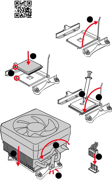
Installing a Processor/ Installation des Prozessors/ Installer un processeur/Установкапроцессора
|
1 |
3
2 


5 4
|
6 |
8 |
|
|
9 |
||
|
7 |
II Quick Start
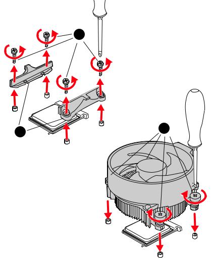
If you are installing the screw-type CPU heatsink, please follow the figure below to remove the retention module first and then install the heatsink.
Wenn Sie einen CPU-Kühler mit Schraubenbefestigung einsetzen, folgen Sie bitte den Anweisungen unten um das Retention-Modul zu entfernen und den Kühler zu installieren.
Si vous voulez installer un ventirad pour processeur à vis, veuillez suivre les instructions ci-dessous pour d’abord retirer le module de rétention puis installer le ventirad.
В случае установки процессорного кулера с системой крепления на винтах, следуйте указаниям на рисунке ниже для снятия пластикового модуля крепления. Затем установите кулер.
1
Quick Start III

Installing DDR4 memory/ Installation des DDR4-Speichers/
InstallerunemémoireDDR4/УстановкапамятиDDR4
|
DIMMA2 |
DIMMA2 |
DIMMA1 |
|
DIMMA2 |
||
|
DIMMB2 |
DIMMB1 |
|
|
DIMMB2 |
IV Quick Start
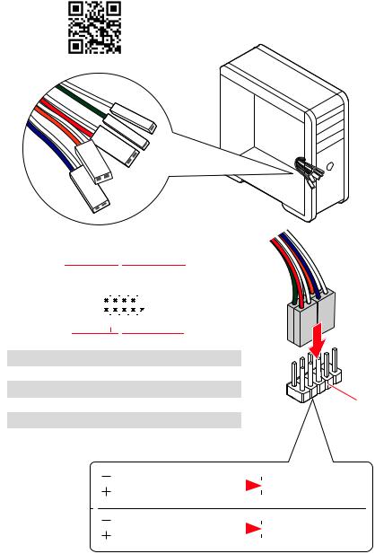
Connecting the Front Panel Header/ Anschließen der Frontpanel-Stiftleiste/ Connecter un connecteur du panneau avant/Подключениеразъемовпереднейпанели
|
— |
|||
|
LED |
|||
|
LED+ |
POWER |
||
|
POWER |
|||
|
LED |
|||
|
SW |
HDD |
||
|
POWER |
|||
|
SW |
|||
|
RESET |
|
Power LED |
Power Switch |
||||||||||||||||||
|
-+-+ |
|||||||||||||||||||
|
JFP1 |
2 |
10 |
|||||||||||||||||
|
1 |
9 |
Reserved |
|||||||||||||||||
|
+ +— |
|||||||||||||||||||
|
HDD LED |
Reset Switch |
||||||||||||||||||
|
1 |
HDD LED + |
2 |
Power LED + |
||||||||||||||||
|
3 |
HDD LED — |
4 |
Power LED — |
||||||||||||||||
|
5 |
Reset Switch |
6 |
Power Switch |
||||||||||||||||
|
7 |
Reset Switch |
8 |
Power Switch |
||||||||||||||||
|
9 |
Reserved |
10 |
No Pin |
HDDLED RESETSW
|
HDD LED — |
|||||||
|
HDD LED |
|||||||
|
HDD LED + |
|||||||
|
POWER LED — |
|||||||
|
POWER LED |
POWER LED + |
||||||
Quick Start V

Installing the Motherboard/ Installation des Motherboards/
Installerlacartemère/Установкаматеринскойплаты
1
*3 kgf·cm = 0.3 N·m = 2.6 lbf·in
VI Quick Start

Connecting the Power Connectors/ Stromanschlüsse anschliessen/ Connecter les câbles du module d’alimentation/
Подключениеразъемовпитания
ATX_PWR1
 CPU_PWR1
Quick Start VII
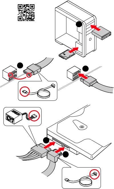
Installing SATA Drives/ Installation der SATA-Laufwerke/
InstallerledisquedurSATA/УстановкадисковSATA
|
1 |
5
4
VIII Quick Start
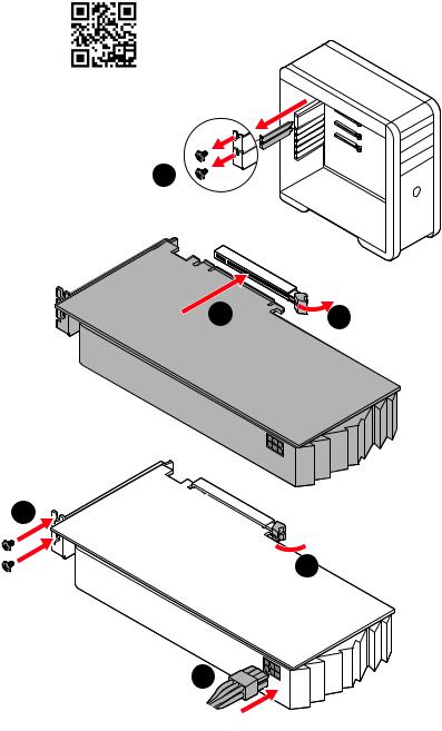
Installing a Graphics Card/ Einbau der Grafikkarte/ Installer unecartegraphique/Установкадискретнойвидеокарты
1
5
 4
4
6
Quick Start IX
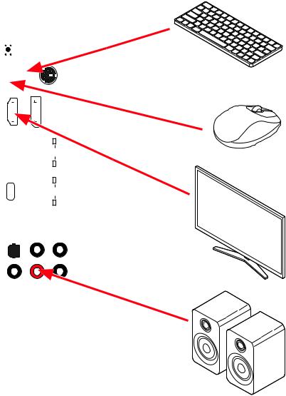
Connecting Peripheral Devices/ Peripheriegeräte/ Connecter unpériphériqueanschliessen/Подключениепериферийных устройств
|
Processor |
||||||||||||
|
with |
||||||||||||
|
integrated |
graphics |
|||||||||||
X Quick Start
![]()
PowerOn/Einschalten/Mettresous-tension/Включение питания
1


 2
2
3
4
Quick Start XI
|
Contents |
|
|
Safety Information……………………………………………………………………………………. |
3 |
|
Specifications…………………………………………………………………………………………… |
4 |
|
Package contents……………………………………………………………………………………… |
9 |
|
Rear I/O Panel………………………………………………………………………………………… |
10 |
|
LAN Port LED Status Table……………………………………………………………………….. |
10 |
|
Audio Ports Configuration…………………………………………………………………………. |
10 |
|
Realtek Audio Console……………………………………………………………………………… |
11 |
|
Overview of Components…………………………………………………………………………. |
13 |
|
Processor Socket…………………………………………………………………………………….. |
14 |
|
DIMM Slots……………………………………………………………………………………………… |
15 |
|
PCI_E1~4: PCIe Expansion Slots……………………………………………………………….. |
16 |
|
SATA1~6: SATA 6Gb/s Connectors…………………………………………………………….. |
17 |
|
M2_1~2: M.2 Slots (Key M)………………………………………………………………………… |
17 |
|
JFP1, JFP2: Front Panel Connectors…………………………………………………………. |
19 |
|
JAUD1: Front Audio Connector………………………………………………………………….. |
19 |
|
CPU_PWR1, ATX_PWR1: Power Connectors……………………………………………….. |
20 |
|
JUSB4: USB 3.2 Gen 1 5Gbps Type-C Connector…………………………………………. |
21 |
|
JUSB3: USB 3.2 Gen 1 5Gbps Connector…………………………………………………….. |
21 |
|
JUSB1~2: USB 2.0 Connectors………………………………………………………………….. |
22 |
|
JTPM1: TPM Module Connector………………………………………………………………… |
22 |
|
CPU_FAN1, PUMP_FAN1, SYS_FAN1~6: Fan Connectors……………………………. |
23 |
|
JCI1: Chassis Intrusion Connector…………………………………………………………….. |
24 |
|
JBAT1: Clear CMOS (Reset BIOS) Jumper………………………………………………….. |
25 |
|
JRGB1~2: RGB LED connectors…………………………………………………………………. |
26 |
|
JRAINBOW1~2: Addressable RGB LED connectors……………………………………… |
27 |
|
EZ Debug LED…………………………………………………………………………………………. |
28 |
|
LED_SW1: EZ LED Control………………………………………………………………………… |
28 |
|
Installing OS, Drivers & Utilities……………………………………………………………….. |
29 |
|
Installing Windows® 10……………………………………………………………………………… |
29 |
|
Installing Drivers……………………………………………………………………………………… |
29 |
|
Installing Utilities…………………………………………………………………………………….. |
29 |
|
UEFI BIOS………………………………………………………………………………………………. |
30 |
|
BIOS Setup……………………………………………………………………………………………… |
31 |
|
Entering BIOS Setup………………………………………………………………………………… |
31 |
|
Resetting BIOS………………………………………………………………………………………… |
32 |
|
Updating BIOS…………………………………………………………………………………………. |
32 |
|
EZ Mode………………………………………………………………………………………………….. |
34 |
Contents 1
|
Advanced Mode ………………………………………………………………………………………. |
37 |
|
OC Menu…………………………………………………………………………………………………. |
38 |
2 Contents
Safety Information
∙∙The components included in this package are prone to damage from electrostatic discharge (ESD). Please adhere to the following instructions to ensure successful computer assembly.
∙∙Ensure that all components are securely connected. Loose connections may cause the computer to not recognize a component or fail to start.
∙∙Hold the motherboard by the edges to avoid touching sensitive components. ∙∙It is recommended to wear an electrostatic discharge (ESD) wrist strap when
handling the motherboard to prevent electrostatic damage. If an ESD wrist strap is not available, discharge yourself of static electricity by touching another metal object before handling the motherboard.
∙∙Store the motherboard in an electrostatic shielding container or on an anti-static pad whenever the motherboard is not installed.
∙∙Before turning on the computer, ensure that there are no loose screws or metal components on the motherboard or anywhere within the computer case.
∙∙Do not boot the computer before installation is completed. This could cause permanent damage to the components as well as injury to the user.
∙∙If you need help during any installation step, please consult a certified computer technician.
∙∙Always turn off the power supply and unplug the power cord from the power outlet before installing or removing any computer component.
∙∙Keep this user guide for future reference. ∙∙Keep this motherboard away from humidity.
∙∙Make sure that your electrical outlet provides the same voltage as is indicated on the PSU, before connecting the PSU to the electrical outlet.
∙∙Place the power cord such a way that people can not step on it. Do not place anything over the power cord.
∙∙All cautions and warnings on the motherboard should be noted.
∙∙If any of the following situations arises, get the motherboard checked by service personnel:
▪▪Liquid has penetrated into the computer.
▪▪The motherboard has been exposed to moisture.
▪▪The motherboard does not work well or you can not get it work according to user guide.
▪▪The motherboard has been dropped and damaged. ▪▪The motherboard has obvious sign of breakage.
∙∙Do not leave this motherboard in an environment above 60°C (140°F), it may damage the motherboard.
Safety Information 3

Specifications
|
CPU |
Supports AM4 socket 3rd Gen AMD Ryzen™ processors, and |
|
future AMD Ryzen™ processors with BIOS update |
|
|
Chipset |
AMD B550 Chipset |
|
∙∙4x DDR4 memory slots, support up to 128GB* |
|
|
▪▪Supports DDR4 1866/ 2133/ 2400/ 2667/ 2800/ 2933/ |
|
|
3000/ 3066/ 3200 MHz by JEDEC |
|
|
▪▪Supports DDR4 2667/ 2800 /2933 /3000 /3066 /3200 |
|
|
/3466 /3600/ 3733 /3866 /4000 /4133 /4266 /4400 /4533 |
|
|
/4600 /4733/ 4800/ 4866+ MHz by A-XMP OC MODE |
|
|
▫▫1DPC 1R max speed 4866 MHZ |
|
|
Memory |
▫▫1DPC 2R max speed 3866 MHZ |
|
▫▫2DPC 1R max speed 4000 MHZ |
|
|
▫▫2DPC 2R max speed 3600 MHZ |
|
|
∙∙Dual channel memory architecture |
|
|
∙∙Supports non-ECC UDIMM memory |
|
|
∙∙Supports ECC UDIMM memory (non-ECC mode) |
|
|
∙∙Supports un-buffered memory |
|
|
* Please refer www.msi.com for more information on compatible memory. |
|
|
∙∙1x PCIe 4.0/ 3.0 x16 slot (PCI_E1)* |
|
|
∙∙1x PCIe 3.0 x16 slot (PCI_E3), supports x4 speed** |
|
|
Expansion Slot |
∙∙2x PCIe 3.0 x1 slots |
|
* The supported specification depends on installed processor. |
|
|
** When installing devices in M.2_2, PCI_E2 & PCI_E3 slots at the same time, |
|
|
PCI_E3 slot will be unavailable, and M2_2 slot only supports PCIe x2. Please |
|
|
refer to page 16 for details. |
|
|
Multi-GPU |
∙∙Supports 2-Way AMD CrossFire™ Technology |
|
∙∙1x HDMI port, supports a maximum resolution of |
|
|
4096×2160 @24Hz* |
|
|
Onboard Graphics |
∙∙1x DisplayPort, supports a maximum resolution of |
|
4096×2160 @60Hz* |
|
|
∙∙Maximum shared memory of 2048 MB |
|
|
* Available for the processor with integrated graphics. |
|
|
Continued on next page |
4 Specifications

Continued from previous page
|
AMD B550 Chipset |
|
|
∙∙6x SATA 6Gb/s ports |
|
|
∙∙2x M.2 slots (Key M) |
|
|
▪▪M2_1 slot (from AMD Processor) |
|
|
Storage |
▫▫Supports PCIe 4.0/ 3.0 x4* |
|
▫▫Supports SATA 6Gb/s |
|
|
▫▫Supports 2242/ 2260/ 2280/ 22110 storage devices |
|
|
▪▪M2_2 slot (from AMD B550 chipset) |
|
|
▫▫Supports PCIe 3.0×4 |
|
|
▫▫Supports 2242/ 2260/ 2280 storage devices |
|
|
* The supported specification depends on installed processor. |
|
|
RAID |
∙∙Supports RAID 0, RAID 1 and RAID 10 for SATA storage |
|
devices |
|
|
∙∙Supports RAID 0 and RAID 1 for M.2 NVMe storage devices |
|
|
AMD B550 Chipset |
|
|
▪▪3x USB 3.2 Gen 1 5Gbps ports (1 Type-C internal |
|
|
connector, and 2 ports are available through the internal |
|
|
USB 3.2 Gen 1 5Gbps connector) |
|
|
USB |
▪▪6x USB 2.0 ports (2 Type-A ports on the back panel, 4 |
|
ports through the internal USB 2.0 connectors) |
|
|
AMD Processor |
|
|
▪▪2x USB 3.2 Gen 2 10Gbps ports (1 Type-C port and 1 |
|
|
Type-A port on the back panel) |
|
|
▪▪2x USB 3.2 Gen 1 5Gbps Type-A ports on the back |
|
|
panel |
|
|
Audio |
Realtek® ALC1200 Codec |
|
▪▪7.1-Channel High Definition Audio |
|
|
▪▪Supports S/PDIF output |
|
|
LAN |
∙∙1x Realtek® RTL8125B 2.5Gbps LAN controller |
|
∙∙1x Realtek® RTL8111H 1Gbps LAN controller |
|
|
Continued on next page |
Specifications 5

Continued from previous page
∙∙1x 24-pin ATX main power connector ∙∙1x 8-pin ATX 12V power connector
∙∙6x SATA 6Gb/s connectors
∙∙2x M.2 slots (M-Key)
∙∙1x USB 3.2 Gen 1 5Gbps Type-C port
∙∙1x USB 3.2 Gen 1 5Gbps connector (supports additional 2 USB 3.2 Gen 1 5Gbps ports)
∙∙2x USB 2.0 connectors (supports additional 4 USB 2.0 ports)
Internal Connectors ∙∙1x 4-pin CPU fan connector
∙∙1x 4-pin water-pump fan connector ∙∙6x 4-pin system fan connectors
∙∙1x Front panel audio connector ∙∙2x System panel connectors
∙∙1x Chassis Intrusion connector
∙∙2x 4-pin RGB LED connectors
∙∙2x 3-pin RAINBOW LED connectors
∙∙1x TPM module connector ∙∙1x Clear CMOS jumper
|
LED Features |
∙∙1x EZ LED Control switch |
||
|
∙∙4x EZ Debug LED |
|||
|
∙∙1x Flash BIOS Button |
|||
|
∙∙1x PS/2 keyboard/ mouse combo port |
|||
|
∙∙2x USB 2.0 Type-A ports |
|||
|
∙∙1x |
Display port |
||
|
Back Panel |
∙∙1x HDMI port |
||
|
∙∙2x |
LAN (RJ45) ports |
||
|
Connectors |
|||
|
∙∙2x USB 3.2 Gen 1 5Gbps Type-A ports |
|||
|
∙∙1x USB 3.2 Gen 2 10Gbps Type-A port |
|||
|
∙∙1x USB 3.2 Gen 2 10Gbps Type-C port |
|||
|
∙∙5x |
OFC audio jacks |
||
|
∙∙1x |
Optical S/PDIF Out connector |
||
|
Continued on next page |
6 Specifications

|
Continued from previous page |
|||
|
I/O Controller |
NUVOTON NCT6687-R Controller Chip |
||
|
Hardware Monitor |
∙∙CPU/ System/ Chipset temperature detection |
||
|
∙∙CPU/ System/ Pump fan speed detection |
|||
|
∙∙CPU/ System/ Pump fan speed control |
|||
|
Form Factor |
∙∙ATX Form Factor |
||
|
∙∙12 in. x 9.6 in. (30.5 cm x 24.4 cm) |
|||
|
∙∙1x 256 Mb flash |
|||
|
BIOS Features |
∙∙UEFI AMI BIOS |
||
|
∙∙ACPI 6.0, SMBIOS 2.8 |
|||
|
∙∙Multi-language |
|||
|
∙∙Drivers |
|||
|
∙∙DRAGON CENTER |
|||
|
Software |
∙∙MSI APP Player (BlueStacks) |
||
|
∙∙Open Broadcaster Software (OBS) |
|||
|
∙∙CPU-Z MSI GAMING |
|||
|
∙∙Google Chrome™, Google Toolbar, Google Drive |
|||
|
∙∙Norton™ Internet Security Solution |
|||
|
∙∙Gaming Mode |
|||
|
∙∙Gaming Hotkey |
|||
|
∙∙LAN Manager |
|||
|
∙∙Mystic Light |
|||
|
Dragon Center |
∙∙User Scenario |
||
|
∙∙Hardware Monitor |
|||
|
Features |
|||
|
∙∙True Color |
Please refer to http://download.msi. |
||
|
∙∙Live Update |
com/manual/mb/DRAGONCENTER2. |
||
|
∙∙Speed Up |
pdf for more details. |
||
|
∙∙Smart Tool |
|||
|
∙∙Super Charger |
|||
|
Continued on next page |
Specifications 7

Continued from previous page
∙∙Audio
▪▪Audio Boost ∙∙Network
▪▪2.5G LAN
▪▪LAN Manager with Realtek 8125B ∙∙Cooling
▪▪Extended Heatsink Design
▪▪M.2 Shield Frozr
▪▪Pump Fan
▪▪Smart Fan Control
∙∙LED
▪▪Mystic Light Extension (RAINBOW/RGB)
▪▪Mystic Light SYNC
▪▪EZ LED Control
▪▪EZ DEBUG LED
Special Features ∙∙Performance
▪▪Multi GPU-CrossFire Technology
▪▪DDR4 Boost
▪▪Core Boost
▪▪GAME Boost ▪▪USB 3.2 Gen 2 10G ▪▪USB with Type A+C
▪▪Front USB Type-C
∙∙Protection
▪▪PCI-E Steel Armor ▪▪PCI-E Steel Slot ▪▪Pre-installed I/O Shielding
∙∙Experience ▪▪Dragon Center ▪▪Click BIOS 5 ▪▪Flash BIOS Button
8 Specifications

Package contents
Please check the contents of your motherboard package. It should contain:
|
Motherboard |
MAG B550 TOMAHAWK |
|
|
Cable |
SATA 6G cables (2 cables/pack) |
1 |
|
Accessories |
M.2 screws (3 pcs./pack) |
1 |
|
Case badge |
1 |
|
|
Product registration card |
1 |
|
|
Application |
Driver DVD |
1 |
|
Documentation |
User manual |
1 |
|
Quick installation guide |
1 |
|
|
MSI components compatibility & reward program |
1 |
|
|
card |
Important
If any of the above items are damaged or missing, please contact your retailer.
Package contents 9
![]()
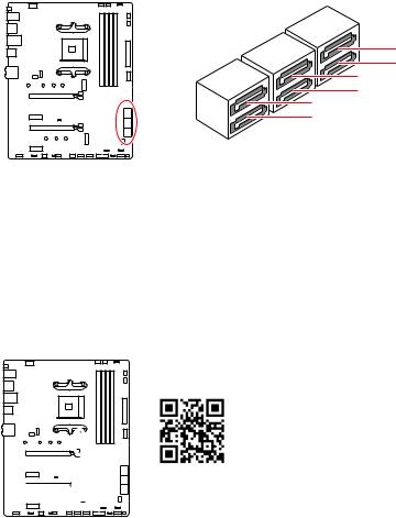
Rear I/O Panel
|
PS/2 Combo port |
1 Gbps LAN |
Audio Ports |
|
Flash BIOS |
2.5 Gbps LAN |
|
|
Button |
DisplayPort |
|
USB 3.2 Gen 1 |
USB 3.2 Gen 2 |
|||||||||||||||||||||||||||||||||||||||
|
Flash BIOS |
||||||||||||||||||||||||||||||||||||||||
|
Port |
(5Gbps) Type-A |
(10Gbps) Type-A |
||||||||||||||||||||||||||||||||||||||
|
USB |
2.0 |
USB 3.2 |
Gen 2 |
Optical |
||||||||||||||||||||||||||||||||||||
|
Type-A |
(10Gbps) Type-C |
S/PDIF-Out |
∙∙Flash BIOS Port/ Button — Please refer to page 33 for Updating BIOS with Flash BIOS Button.
LAN Port LED Status Table
Link/ Activity LED
|
Status |
Description |
|
Off |
No link |
|
Yellow |
Linked |
|
Blinking |
Data activity |
Speed LED
|
Status |
2.5 Gbps LAN |
1 Gbps LAN |
|
Off |
10 Mbps |
10 Mbps |
|
Green |
100/ 1000 Mbps |
100 Mbps |
|
Orange |
2.5 Gbps |
1 Gbps |
Audio Ports Configuration |
Channel |
||||
|
Audio Ports |
|||||
|
2 |
4 |
6 |
8 |
||
|
Center/ Sub-woofer Out |
● |
● |
|||
|
Rear Speaker Out |
● |
● |
● |
|
Line-In/ Side Speaker Out |
● |
|
Line-Out/ Front Speaker Out |
● |
● |
● |
● |
|
Mic In |
||||
|
(●: connected, Blank: empty) |
10 Rear I/O Panel
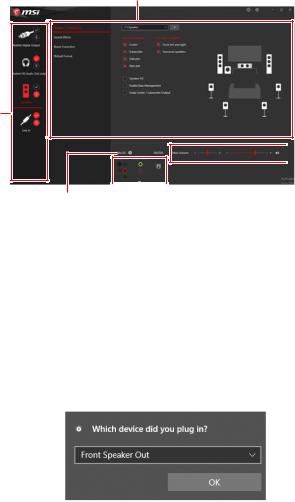
Realtek Audio Console
After Realtek Audio Console is installed. You can use it to change sound settings to get better sound experience.
Application Enhancement
Device
Selection
 Main Volume
|
Connector Settings |
||
|
Jack Status |
∙∙Device Selection — allows you to select a audio output source to change the related options. The check sign indicates the devices as default.
∙∙Application Enhancement — the array of options will provide you a complete guidance of anticipated sound effect for both output and input device.
∙∙Main Volume — controls the volume or balance the right/left side of the speakers that you plugged in front or rear panel by adjust the bar.
∙∙Jack Status — depicts all render and capture devices currently connected with your computer.
∙∙Connector Settings — configures the connection settings.
Auto popup dialog
When you plug into a device at an audio jack, a dialogue window will pop up asking you which device is current connected.
Each jack corresponds to its default setting as shown on the next page.
Important
The pictures above for reference only and may vary from the product you purchased.
Rear I/O Panel 11
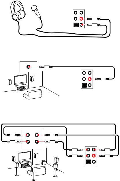
Audio jacks to headphone and microphone diagram
Audio jacks to stereo speakers diagram
AUDIO INPUT
Audio jacks to 7.1-channel speakers diagram
AUDIO INPUT
|
Rear |
Front |
|
Side |
Center/ |
|
Subwoofer |
12 Rear I/O Panel

Overview of Components
JTPM1
SYS_FAN6
M2_1
PCI_E1
JBAT1
PCI_E2
PCI_E3
M2_2
PCI_E4
|
Processor Socket |
CPU_FAN1 |
|
|
CPU_PWR1 |
PUMP_FAN1 |
|
|
JRAINBOW2 |
||
|
SYS_FAN1 |
||
|
SYS_FAN2 |
||
|
ATX_PWR1 |
||
|
JUSB4 |
||
|
DIMMB2 |
||
|
DIMMB1 |
||
|
DIMMA2 |
||
|
DIMMA1 |
||
|
SATA▼5▲6 |
||
|
SATA▼1▲2 |
||
|
SATA▼3▲4 |
||
|
SYS_FAN3 |
||
|
JRGB2 |
||
|
JRAINBOW1 |
||
|
JPWRLED1 |
|
JAUD1 |
JRGB1 |
JUSB3 |
JFP2JFP1 |
|
|
SYS_FAN5 |
JUSB2 |
|||
|
JCI1 |
||||
|
LED_SW1 |
JUSB1 |
|||
|
SYS_FAN4 |
Overview of Components 13
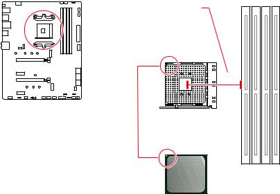
Processor Socket
Distance from the center of the
CPU to the nearest DIMM slot.
53.8 mm
Introduction to the AM4 CPU
The surface of the AM4 CPU has a yellow triangle to assist in correctly lining up the CPU for motherboard placement. The yellow triangle is the Pin 1 indicator.
Important
∙∙When changing the processor, the system configuration could be cleared and reset BIOS to default values, due to the AM4 processor’s architecture.
∙∙Always unplug the power cord from the power outlet before installing or removing the CPU.
∙∙When installing a CPU, always remember to install a CPU heatsink. A CPU heatsink is necessary to prevent overheating and maintain system stability.
∙∙Confirm that the CPU heatsink has formed a tight seal with the CPU before booting your system.
∙∙Overheating can seriously damage the CPU and motherboard. Always make sure the cooling fans work properly to protect the CPU from overheating. Be sure to apply an even layer of thermal paste (or thermal tape) between the CPU and the heatsink to enhance heat dissipation.
∙∙If you purchased a separate CPU and heatsink/ cooler, Please refer to the documentation in the heatsink/ cooler package for more details about installation. ∙∙This motherboard is designed to support overclocking. Before attempting to overclock, please make sure that all other system components can tolerate overclocking. Any attempt to operate beyond product specifications is not recommended. MSI® does not guarantee the damages or risks caused by inadequate operation beyond product specifications.
14 Overview of Components

DIMM Slots
|
DIMMA1 |
DIMMB1 |
|||||||||||||||||||||||||||||
|
Channel A |
Channel B |
|||||||||||||||||||||||||||||
|
DIMMA2 |
DIMMB2 |
|||||||||||||||||||||||||||||
Memory module installation recommendation
|
DIMMA1 |
|||
|
DIMMA2 |
DIMMA2 |
DIMMA2 |
|
|
DIMMB1 |
|||
|
∙∙ |
DIMMB2 |
DIMMB2 |
|
Important
Always insert memory modules in the DIMMA2 slot first.
∙∙Due to chipset resource usage, the available capacity of memory will be a little less than the amount of installed.
∙∙Based on CPU specification, the Memory DIMM voltage below 1.35V is suggested to protect the CPU.
∙∙To ensure system stability for Dual channel mode, memory modules must be of the same type, number and density.
∙∙Some memory modules may operate at a lower frequency than the marked value when overclocking due to the memory frequency operates dependent on its Serial Presence Detect (SPD). Go to BIOS and find the DRAM Frequency to set the memory frequency if you want to operate the memory at the marked or at a higher frequency. ∙∙It is recommended to use a more efficient memory cooling system for full DIMMs installation or overclocking.
∙∙The stability and compatibility of installed memory module depend on installed CPU and devices when overclocking.
∙∙Please refer www.msi.com for more information on compatible memory.
Overview of Components 15
PCI_E4: PCIe 3.0 x1 (PCH)
PCI_E1~4: PCIe Expansion Slots


 PCI_E1: PCIe 3.0/ 4.0 x16 (CPU)
PCI_E2: PCIe 3.0 x1 (PCH)

 PCI_E3: PCIe 3.0 x4 (PCH)
Important
∙∙If you install a large and heavy graphics card, you need to use a tool such as MSI Gaming Series Graphics Card Bolster to support its weight to prevent deformation of the slot.
∙∙For a single PCIe x16 expansion card installation with optimum performance, using the PCI_E1 slot is recommended.
∙∙When adding or removing expansion cards, always turn off the power supply and unplug the power supply power cable from the power outlet. Read the expansion card’s documentation to check for any necessary additional hardware or software changes.
∙∙When installing devices in M.2_2, PCI_E2 & PCI_E3 slots at the same time, PCI_E3 slot will be unavailable, and M2_2 slot only supports PCIe x2.
M.2 slots and PCIe slots combination table
|
Slot |
Combination |
|||
|
M2_1 (CPU) |
PCIe x2 |
PCIe/SATA |
X |
|
|
M2_2 (PCH) |
PCIe x4 |
X |
||
|
PCI_E1 (CPU) |
||||
|
PCI_E2 (PCH) |
X |
X |
||
|
PCI_E3 (PCH) |
─ |
X |
PCIe x2 |
PCIe x4 |
|
PCI_E4 (PCH) |
(SATA: M.2 SATA SSD, PCIe: M.2 PCIe SSD, X: no device, : available, ─: unavailable)
16 Overview of Components
SATA1~6: SATA 6Gb/s Connectors
These connectors are SATA 6Gb/s interface ports. Each connector can connect to one SATA device.
SATA6
SATA2
SATA4 SATA1
SATA3
SATA5
Important
∙∙Please do not fold the SATA cable at a 90-degree angle.Data loss may result during transmission otherwise.
∙∙SATA cables have identical plugs on either sides of the cable. However, it is recommended that the flat connector be connected to the motherboard for space saving purposes.
M2_1~2: M.2 Slots (Key M)

 M2_1
M2_1

 M2_2
M2_2
Video Demonstration
Watch the video to learn how to Install M.2 module. http://youtu.be/JCTFABytrYA
Installing M.2 module
1. Loosen the screws of M.2 SHIELD FROZR heatsink.
2. Remove the M.2 SHIELD FROZR and remove the protective films from the thermal pads.
Overview of Components 17

heatsink standoff
6. Put the M.2 SHIELD FROZR heatsink back in place and secure it.
6
6
6  6
6
18 Overview of Components
JFP1
|
-+-+ |
||||||||
|
2 |
10 |
|||||||
|
1 |
9 |
Reserved |
||||||
|
+ +— |
 HDD LED

 Reset Switch
|
1 |
HDD LED + |
2 |
Power LED + |
|
3 |
HDD LED — |
4 |
Power LED — |
|
5 |
Reset Switch |
6 |
Power Switch |
|
7 |
Reset Switch |
8 |
Power Switch |
|
9 |
Reserved |
10 |
No Pin |
JFP2
|
Buzzer |
1 |
Speaker — |
2 |
Buzzer + |
|||||
|
Speaker |
|||||||||
|
3 |
Buzzer — |
4 |
Speaker + |
||||||
JAUD1: Front Audio Connector
This connector allows you to connect audio jacks on the front panel.
|
2 |
10 |
||
|
1 |
9 |
||
|
1 |
MIC L |
2 |
Ground |
|
3 |
MIC R |
4 |
NC |
|
5 |
Head Phone R |
6 |
MIC Detection |
|
7 |
SENSE_SEND |
8 |
No Pin |
|
9 |
Head Phone L |
10 |
Head Phone Detection |
Overview of Components 19
![]()
CPU_PWR1, ATX_PWR1: Power Connectors
These connectors allow you to connect an ATX power supply.
|
8 |
5 |
CPU_PWR1 |
|||||||||||||||||||||||||||||||||
|
4 |
1 |
||||||||||||||||||||||||||||||||||
|
1 |
Ground |
5 |
+12V |
||||||||||||||||||||||||||||||||
|
2 |
Ground |
6 |
+12V |
||||||||||||||||||||||||||||||||
|
3 |
Ground |
7 |
+12V |
||||||||||||||||||||||||||||||||
|
4 |
Ground |
8 |
+12V |
||||||||||||||||||||||||||||||||
|
1 |
+3.3V |
13 |
+3.3V |
|||||
|
2 |
+3.3V |
14 |
-12V |
|||||
|
12 |
24 |
3 |
Ground |
15 |
Ground |
|||
|
4 |
+5V |
16 |
PS-ON# |
|||||
|
5 |
Ground |
17 |
Ground |
|||||
|
ATX_PWR1 |
6 |
+5V |
18 |
Ground |
||||
|
7 |
Ground |
19 |
Ground |
|||||
|
1 |
13 |
8 |
PWR OK |
20 |
Res |
|||
|
9 |
5VSB |
21 |
+5V |
|||||
|
10 |
+12V |
22 |
+5V |
|||||
|
11 |
+12V |
23 |
+5V |
|||||
|
12 |
+3.3V |
24 |
Ground |
|||||
|
Important |
||||||||
|
Make sure that all the power cables are securely connected to a proper ATX power |
||||||||
|
supply to ensure stable operation of the motherboard. |
20 Overview of Components

JUSB4: USB 3.2 Gen 1 5Gbps Type-C Connector
This connector allows you to connect USB 3.2 Gen 1 5Gbps Type-C connector on the front panel. The connector possesses a foolproof design. When you connect the cable, be sure to connect it with the corresponding orientation.
USB Type-C port on the front panel
JUSB3: USB 3.2 Gen 1 5Gbps Connector
This connector allows you to connect USB 3.2 Gen 1 5Gbps ports on the front panel.
Important
|
1 |
10 |
||
|
20 |
11 |
||
|
1 |
Power |
11 |
USB2.0+ |
|
2 |
USB3_RX_DN |
12 |
USB2.0- |
|
3 |
USB3_RX_DP |
13 |
Ground |
|
4 |
Ground |
14 |
USB3_TX_C_DP |
|
5 |
USB3_TX_C_DN |
15 |
USB3_TX_C_DN |
|
6 |
USB3_TX_C_DP |
16 |
Ground |
|
7 |
Ground |
17 |
USB3_RX_DP |
|
8 |
USB2.0- |
18 |
USB3_RX_DN |
|
9 |
USB2.0+ |
19 |
Power |
|
10 |
Ground |
20 |
No Pin |
Note that the Power and Ground pins must be connected correctly to avoid possible damage.
Overview of Components 21

JUSB1~2: USB 2.0 Connectors
These connectors allow you to connect USB 2.0 ports on the front panel.
|
2 |
10 |
|||
|
1 |
9 |
|||
|
1 |
VCC |
2 |
VCC |
|
|
3 |
USB0- |
4 |
USB1- |
|
|
5 |
USB0+ |
6 |
USB1+ |
|
|
7 |
Ground |
8 |
Ground |
|
|
∙∙ |
9 |
No Pin |
10 |
NC |
|
Important |
Note that the VCC and Ground pins must be connected correctly to avoid possible damage.
∙∙In order to recharge your iPad,iPhone and iPod through USB ports, please install MSI® DRAGON CENTER utility.
JTPM1: TPM Module Connector
This connector is for TPM (Trusted Platform Module). Please refer to the TPM security platform manual for more details and usages.
|
12 |
11 |
||||||||||||||||||||||||||||
|
2 |
1 |
||||||||||||||||||||||||||||
|
1 |
SPI Power |
2 |
SPI Chip Select |
||||||||||||||||||||||||||
|
3 |
Master In Slave Out (SPI Data) |
4 |
Master In Slave In (SPI Data) |
||||||||||||||||||||||||||
|
5 |
Reserved |
6 |
SPI Clock |
||||||||||||||||||||||||||
|
7 |
Ground |
8 |
SPI Reset |
||||||||||||||||||||||||||
|
9 |
Reserved |
10 |
No Pin |
||||||||||||||||||||||||||
|
11 |
Reserved |
12 |
Interrupt Request |
22 Overview of Components

There are gradient points of the fan speed that allow you to adjust fan speed in relation to CPU temperature.
CPU_FAN1, PUMP_FAN1, SYS_FAN1~6: Fan Connectors
Fan connectors can be classified as PWM (Pulse Width Modulation) Mode or DC Mode. PWM Mode fan connectors provide constant 12V output and adjust fan speed with speed control signal. DC Mode fan connectors control fan speed by changing voltage. The auto mode fan connectors can automatically detect PWM and DC mode. However, you can follow the instruction below to adjust the fan connector to PWM or DC Mode manually.
SYS_FAN6 CPU_FAN1 PUMP_FAN1
SYS_FAN1

 SYS_FAN2
|
Connector |
Default fan |
Max. |
Max. |
|||||||||||||||
|
mode |
current |
power |
||||||||||||||||
|
CPU_FAN1 |
Auto mode |
2A |
24W |
|||||||||||||||
|
PUMP_FAN1 |
PWM mode |
3A |
36W |
|||||||||||||||
|
SYS_FAN1~6 |
DC mode |
1A |
12W |
 SYS_FAN3
SYS_FAN5 SYS_FAN4
Switching fan mode and adjusting fan speed
You can switch between PWM mode and DC mode and adjust fan speed in BIOS > HARDWARE MONITOR.
Select PWM mode or DC mode
Important
Make sure fans are working properly after switching the PWM/ DC mode.
Pin definition of fan connectors
|
1 |
PWM Mode pin definition |
||||
|
1 |
Ground |
2 |
+12V |
||
|
3 |
Sense |
4 |
Speed Control Signal |
|
1 |
DC Mode pin definition |
||||
|
1 |
Ground |
2 |
Voltage Control |
||
|
3 |
Sense |
4 |
NC |
Overview of Components 23

JCI1: Chassis Intrusion Connector
This connector allows you to connect the chassis intrusion switch cable.
|
Normal |
Trigger the chassis |
|
(default) |
intrusion event |
Using chassis intrusion detector
1. Connect the JCI1 connector to the chassis intrusion switch/ sensor on the chassis. 2. Close the chassis cover.
3. Go to BIOS > SETTINGS > Security > Chassis Intrusion Configuration. 4. Set Chassis Intrusion to Enabled.
5. Press F10 to save and exit and then press the Enter key to select Yes.
6. Once the chassis cover is opened again, a warning message will be displayed on screen when the computer is turned on.
Resetting the chassis intrusion warning
1. Go to BIOS > SETTINGS > Security > Chassis Intrusion Configuration. 2. Set Chassis Intrusion to Reset.
3. Press F10 to save and exit and then press the Enter key to select Yes.
24 Overview of Components

JBAT1: Clear CMOS (Reset BIOS) Jumper
There is CMOS memory onboard that is external powered from a battery located on the motherboard to save system configuration data. If you want to clear the system configuration, set the jumpers to clear the CMOS memory.
Keep Data
(default)
Resetting BIOS to default values
1. Power off the computer and unplug the power cord.
2. Use a jumper cap to short JBAT1 for about 5-10 seconds. 3. Remove the jumper cap from JBAT1.
4. Plug the power cord and Power on the computer.
Overview of Components 25

JRGB1~2: RGB LED connectors
These JRGB connectors allow you to connect the 5050 RGB LED strips 12V.
|
1 |
|||
|
1 |
+12V |
2 |
G |
|
3 |
R |
4 |
B |
RGB LED Strip Connection
1
JRGB connector
B R G
|
RGB extension |
5050 RGB LED strips 12V |
|
cable |
RGB LED Fan Connection
JRGB connector
1


 GR
GR  B
B
1
RGB LED Fan
System Fan connector
Important
∙∙The JRGB connector supports up to 2 meters continuous 5050 RGB LED strips (12V/G/R/B) with the maximum power rating of 3A (12V).
∙∙Always turn off the power supply and unplug the power cord from the power outlet before installing or removing the RGB LED strip.
∙∙Please use MSI’s software to control the extended LED strip.
26 Overview of Components

Addressable RGB LED Fan
JRAINBOW1~2: Addressable RGB LED connectors
The JRAINBOW connectors allow you to connect the WS2812B Individually Addressable RGB LED strips 5V.
|
1 |
|||
|
1 |
+5V |
2 |
Data |
|
3 |
No Pin |
4 |
Ground |
Addressable RGB LED Strip Connection
1 
+5V D
|
JRAINBOW |
|||||||||||
|
Rainbow |
RGB LED |
||||||||||
|
WS2812B Individually |
|||||||||||
|
connector |
extension cable |
Addressable RGB LED Fan Connection
Addressable RGB LED strips 5V
JRAINBOW connector
1 
1
System Fan connector
CAUTION
Do not connect the wrong type of LED strips. The JRGB connector and the JRAINBOW connector provide different voltages, and connecting the 5V LED strip to the JRGB connector will result in damage to the LED strip.
Important
∙∙The JRAINBOW connector supports up to 75 LEDs WS2812B Individually Addressable RGB LED strips (5V/Data/Ground) with the maximum power rating of 3A (5V). In the case of 20% brightness, the connector supports up to 200 LEDs.
∙∙Always turn off the power supply and unplug the power cord from the power outlet before installing or removing the RGB LED strip.
∙∙Please use MSI’s software to control the extended LED strip.
Overview of Components 27

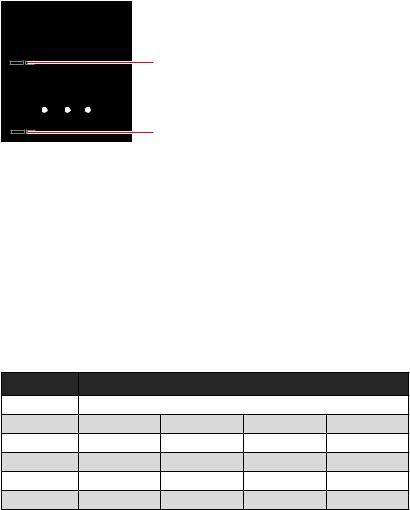
EZ Debug LED
These LEDs indicate the debug status of the motherboard.
CPU — indicates CPU is not detected or fail.
DRAM — indicates DRAM is not detected or fail.
VGA — indicates GPU/ PCIE/ M.2 device is not detected or fail.
BOOT — indicates the booting device is not detected
or fail.
LED_SW1: EZ LED Control
This switch is used to switch on/ off all the LEDs of motherboard.
|
LED_OFF |
LED_ON |
|||||||||||||||||||||||||||||
|
(Default) |
||||||||||||||||||||||||||||||
28 Overview of Components
Installing OS, Drivers & Utilities
Please download and update the latest utilities and drivers at www.msi.com
Installing Windows® 10
1. Power on the computer.
2. Insert the Windows® 10 installation disc/USB into your computer. 3. Press the Restart button on the computer case.
4. Press F11 key during the computer POST (Power-On Self Test) to get into Boot
Menu.
5. Select the Windows® 10 installation disc/USB from the Boot Menu.
6. Press any key when screen shows Press any key to boot from CD or DVD…
message.
7. Follow the instructions on the screen to install Windows® 10.
Installing Drivers
1. Start up your computer in Windows® 10.
2. Insert MSI® Drive Disc into your optical drive.
3. Click the Select to choose what happens with this disc pop-up notification, then select Run DVDSetup.exe to open the installer. If you turn off the AutoPlay feature from the Windows Control Panel, you can still manually execute the DVDSetup.exe from the root path of the MSI Drive Disc.
4. The installer will find and list all necessary drivers in the Drivers/Software tab.
5. Click the Install button in the lower-right corner of the window.
6. The drivers installation will then be in progress, after it has finished it will prompt you to restart.
7. Click OK button to finish.
8. Restart your computer.
Installing Utilities
Before you install utilities, you must complete drivers installation. 1. Open the installer as described above.
2. Click the Utilities tab.
3. Select the utilities you want to install.
4. Click the Install button in the lower-right corner of the window.
5. The utilities installation will then be in progress, after it has finished it will prompt you to restart.
6. Click OK button to finish.
7. Restart your computer.
Installing OS, Drivers & Utilities 29
![]()
UEFI BIOS
MSI UEFI BIOS is compatible with UEFI (Unified Extensible Firmware Interface) architecture. UEFI has many new functions and advantages that traditional BIOS cannot achieve, and it will completely replace BIOS in the future. The MSI UEFI BIOS uses UEFI as the default boot mode to take full advantage of the new chipset’s capabilities. However, it still has a CSM (Compatibility Support Module) mode to be compatible with older devices. That allows you to replace legacy devices with UEFI compatible devices during the transition.
Important
The term BIOS in this user guide refers to UEFI BIOS unless otherwise noted.
UEFI advantages
∙∙Fast booting — UEFI can directly boot the operating system and save the BIOS selftest process. And also eliminates the time to switch to CSM mode during POST.
∙∙Supports for hard drive partitions larger than 2 TB.
∙∙Supports more than 4 primary partitions with a GUID Partition Table (GPT). ∙∙Supports unlimited number of partitions.
∙∙Supports full capabilities of new devices — new devices may not provide backward compatibility.
∙∙Supports secure startup — UEFI can check the validity of the operating system to ensure that no malware tampers with the startup process.
Incompatible UEFI cases
∙∙32-bit Windows operating system — this motherboard supports only Windows 10 64-bit operating system.
∙∙Older graphics card — the system will detect your graphics card. When display a warning message There is no GOP (Graphics Output protocol) support detected in this graphics card.
Important
We recommend that you to use a GOP/ UEFI compatible graphics card.
How to check the BIOS mode?
After entering the BIOS, find the BIOS Mode at the top of the screen.
CPU Temperature:
Motherboard Temperature:
VCore:
DDR Voltage:
BIOS Mode: UEFI
UEFI boot mode
CPU Temperature:
Motherboard Temperature:
VCore:
DDR Voltage:
BIOS Mode: UEFI/Legacy
CSM boot mode
30 UEFI BIOS
BIOS Setup
The default settings offer the optimal performance for system stability in normal conditions. You should always keep the default settings to avoid possible system damage or failure booting unless you are familiar with BIOS.
Important
∙∙BIOS items are continuously update for better system performance. Therefore, the description may be slightly different from the latest BIOS and should be for reference only. You could also refer to the HELP information panel for BIOS item description.
∙∙The pictures in this chapter are for reference only and may vary from the product you purchased.
∙∙The BIOS items will vary with the processor.
Entering BIOS Setup
Press Delete key, when the Press DEL key to enter Setup Menu, F11 to enter Boot Menu message appears on the screen during the boot process.
Function key
F1: General Help list
F2: Add/ Remove a favorite item
F3: Enter Favorites menu
F4: Enter CPU Specifications menu
F5: Enter Memory-Z menu
F6: Load optimized defaults
F7: Switch between Advanced mode and EZ mode
F8: Load Overclocking Profile
F9: Save Overclocking Profile
F10: Save Change and Reset*
F12: Take a screenshot and save it to USB flash drive (FAT/ FAT32 format only). Ctrl+F: Enter Search page
* When you press F10, a confirmation window appears and it provides the modification information. Select between Yes or No to confirm your choice.
UEFI BIOS 31

Resetting BIOS
You might need to restore the default BIOS setting to solve certain problems. There are several ways to reset BIOS:
∙∙Go to BIOS and press F6 to load optimized defaults. ∙∙Short the Clear CMOS jumper on the motherboard.
Important
Be sure the computer is off before clearing CMOS data. Please refer to the Clear CMOS jumper section for resetting BIOS.
Updating BIOS
Updating BIOS with M-FLASH
Before updating:
Please download the latest BIOS file that matches your motherboard model from MSI website. And then save the BIOS file into the USB flash drive.
Updating BIOS:
1. Insert the USB flash drive that contains the update file into the USB port. 2. Please refer the following methods to enter flash mode.
▪▪Reboot and press Ctrl + F5 key during POST and click on Yes to reboot the system.
Press <Ctrl+F5> to activate M-Flash for BIOS update.
▪▪Reboot and press Del key during POST to enter BIOS. Click the M-FLASH button and click on Yes to reboot the system.
3.Select a BIOS file to perform the BIOS update process.
4.After the flashing process is 100% completed, the system will reboot automatically.
32 UEFI BIOS

Updating the BIOS with MSI DRAGON CENTER
Before updating:
Make sure the LAN driver is already installed and the internet connection is set properly.
Updating BIOS:
1. Install and launch MSI DRAGON CENTER and go to Support page. 2. Select Live Update and click on Advance button.
3. Click on Scan button to search the latest BIOS file.
4. Select the BIOS file and click on Download icon to download and install the latest BIOS file.
5. Click Next and choose In Windows mode. And then click Next and Start to start updating BIOS.
6. After the flashing process is 100% completed, the system will restart automatically.
Updating BIOS with Flash BIOS Button
1. Please download the latest BIOS file that matches your motherboard model from the MSI® website.
2. Rename the BIOS file to MSI.ROM, and save it to the root of your USB flash drive. 3. Connect the power supply to CPU_PWR1 and ATX_PWR1. (No need to install CPU
and memory.)
4. Plug the USB flash drive that contains the MSI.ROM file into the Flash BIOS Port on the rear I/O panel.
5. Press the Flash BIOS Button to flash BIOS, and the LED starts flashing. 6. The LED will be turned off when the process is completed.
UEFI BIOS 33

EZ Mode
At EZ mode, it provides the basic system information and allows you to configure the basic setting. To configure the advanced BIOS settings, please enter the Advanced Mode by pressing the Setup Mode switch or F7 function key.
|
A-XMP Profile |
Setup Mode switch |
Screenshot |
Search |
|||||||||||||||||||||||||||||
|
Language |
||||||||||||||||||||||||||||||||
|
System |
||||||||||||||||||||||||||||||||
|
information |
||||||||||||||||||||||||||||||||
|
GAME |
BOOST |
|||||||||||||||||||||||||||||||
|
Boot |
device |
|||||||||||||||||||||||||||||||
|
priority bar |
||||||||||||||||||||||||||||||||
|
Component |
||||||||||||||||||||||||||||||||
|
Information |
||||||||||||||||||||||||||||||||
|
M-Flash |
||||||||||||||||||||||||||||||||
|
Favorites |
||||||||||||||||||||||||||||||||
|
Function |
||||||||||||||||||||||||||||||||
|
Hardware |
buttons |
|||||||||||||||||||||||||||||||
|
Monitor |
||||||||||||||||||||||||||||||||
∙∙GAME BOOST — click on it to toggle the GAME BOOST for overclocking. This function is only available when both of the motherboard and CPU are supporting this function.
Important
We don’t recommend you to adjust any BIOS item after activating the GAME BOOST function for keeping the optimal performance and system stability.
∙∙A-XMP Profile — allows you to select the A-XMP profile for memory to overclock.
This function is only available when the system, memory and CPU are supporting this function.
∙∙Setup Mode switch — press this tab or the F7 key to switch between Advanced mode and EZ mode.
∙∙Screenshot — click on this tab or the F12 key to take a screenshot and save it to USB flash drive (FAT/ FAT32 format only).
∙∙Search — click on this tab or the Ctrl+F keys to enter the search page. It allows you to search by BIOS item name. Move the mouse over a blank space and right click the mouse to exit the search page.
Important
In search page, only the F6, F10 and F12 function keys are available.
∙∙Language — allows you to select language of BIOS setup.
34 UEFI BIOS

∙∙System information — shows the CPU/ DDR speed, CPU/ MB temperature, MB/ CPU type, memory size, CPU/ DDR voltage, BIOS version and build date.
∙∙Boot device priority bar — you can move the device icons to change the boot priority.
The boot priority from high to low is left to right.
∙∙Component Information — click on the CPU, Memory, Storage, Fan Info and Help buttons to show the information of connected component.
∙∙Function buttons — enable or disable these functions by clicking on these buttons.
The function is enabled when the button shows ON .
Important
The function buttons will vary with the motherboard you purchased.
∙∙M-Flash — click on this button to enter the M-Flash menu that provides the way to update BIOS with a USB flash drive.
∙∙Hardware Monitor — click on this button to enter the Hardware Monitor menu that allows you to manually control the fan speed by percentage.
∙∙Favorites — click on this button or press the F3 key to show the Favorites window. It provides 5 menus for you to create personal BIOS menu where you can save and access favorite/ frequently-used BIOS setting items.
UEFI BIOS 35

▪▪To add a BIOS item to a favorite menu
1. Select a BIOS item not only on BIOS menu but also on search page.
2. Right-click or press F2 key.
3. Choose a favorite page and click on OK.
▪▪To delete a BIOS item from favorite menu 1. Select a BIOS item on favorite menu.
2. Right-click or press F2 key.
3. Choose Delete and click on OK.
36 UEFI BIOS

Advanced Mode
Press Setup Mode switch or F7 function key can switch between EZ Mode and Advanced Mode in BIOS setup.
|
BIOS |
menu |
|||||||
|
BIOS menu |
||||||||
|
selection |
selection |
|||||||
Menu display
∙∙BIOS menu selection — the following options are available:
▪▪SETTINGS — allows you to specify the parameters for chipset and boot devices. ▪▪OC — allows you to adjust the frequency and voltage. Increasing the frequency may get better performance.
▪▪M-FLASH — provides the way to update BIOS with a USB flash drive. ▪▪OC PROFILE — allows you to manage overclocking profiles. ▪▪HARDWARE MONITOR — allows you to set the speeds of fans and monitor voltages of system.
▪▪BOARD EXPLORER — provides the information of installed devices on this
motherboard.
∙∙Menu display — provides BIOS setting items and information to be configured.
UEFI BIOS 37
OC Menu
This menu allows you to configure the frequencies and voltages for overclocking. Please note that, higher frequency and voltage may benefit overclocking capability but cause system un-stability.
Important
∙∙Overclocking your PC manually is only recommended for advanced users.
∙∙Overclocking is not guaranteed, and if done improperly, it could void your warranty or severely damage your hardware.
∙∙If you are unfamiliar with overclocking, we advise you to use GAME BOOST function for easy overclocking.
∙∙The BIOS items in OC menu will vary with the processor.
|
OC Explore Mode [Normal] |
|
|
Enables or disables to show the normal or expert version of OC settings. |
|
|
[Normal] |
Provides the regular OC settings in BIOS setup. |
|
[Expert] |
Provides the advanced OC settings for OC expert to configure in BIOS |
setup.
Note: We use * as the symbol for the OC settings of Expert mode.
CPU Ratio [Auto]
Sets the CPU ratio that is used to determine CPU clock speed. This item can only be changed if the processor supports this function.
Advanced CPU Configuration
Press Enter to enter the sub-menu. User can set the parameters about CPU power/ current. The system may become unstable or unbootable after changing the parameters. If it occurs, please clear the CMOS data and restore the default settings.
A-XMP [Disabled]
Please enable A-XMP or select a profile of memory module for overclocking the memory. This item will be available when the installed processor, memory modules and motherboard support this function.
DRAM Frequency [Auto]
Sets the DRAM frequency. Please note the overclocking behavior is not guaranteed.
Adjusted DRAM Frequency
Shows the adjusted DRAM frequency. Read-only.
FCLK Frequency [Auto]
Sets the FCLK frequency (Internal Data Fabric clock of DRAM). Please note the overclocking behavior is not guaranteed.
UCLK DIV1 Mode [Auto]
Sets UCLK (Internal memory controller clock) mode.
38 UEFI BIOS
Memory Try It ! [Disabled]
It can improve memory compatibility or performance by choosing optimized memory preset. This item will be available when the installed processor supports this function.
Memory Failure Retry [Enabled]
Enables or disables the system reboot function when the memory OC retry fails.
Memory Failure Retry Count [2]
Sets the count for memory OC retry. When memory OC retry fails reach the count, the memory will restore the last available settings. This item will display when the
Memory Failure Retry sets to Enabled.
Advanced DRAM Configuration
Press Enter to enter the sub-menu. User can set the memory timing for each/ all memory channel. The system may become unstable or unbootable after changing memory timing. If it occurs, please clear the CMOS data and restore the default settings. (Refer to the Clear CMOS jumper section to clear the CMOS data, and enter the BIOS to load the default settings.)
DigitALL Power sub-menu
Press Enter to enter the sub-menu. In the sub-menu, you can setup some protecting conditions about voltage/ current/ temputure for CPU.
CPU Voltages control [Auto]
These options allows you to set the voltages related to CPU. If set to Auto, BIOS will set these voltages automatically or you can set it manually.
DRAM Voltages control [Auto]
These options allows you to set the voltages related to memory. If set to Auto, BIOS will set these voltages automatically or you can set it manually.
|
Memory Changed Detect [Enabled]* |
|
|
Enables or disables the system to issue a warning message during boot when the |
|
|
memory has been replaced. |
|
|
[Enabled] |
The system will issue a warning message during boot and then you have |
|
[Disabled] |
to load the default settings for new devices. |
|
Disables this function and keeps the current BIOS settings. |
CPU Specifications sub-menu
Press Enter to enter the sub-menu. This sub-menu displays the information of installed CPU. You can also access this information menu at any time by pressing [F4]. Read only.
MEMORY-Z sub-menu
Press Enter to enter the sub-menu. This sub-menu displays all the settings and timings of installed memory. You can also access this information menu at any time by pressing [F5].
UEFI BIOS 39
 Loading…
3.0
Rated 3 out of 5
3 out of 5 stars (based on 1 review)
Your overall rating
MSI MAG B550 TOMAHAWK (01) PDF MANUAL
Click here to download MSI MAG B550 TOMAHAWK (01) PDF MANUAL
MSI MAG B550 TOMAHAWK (01) PDF MANUAL
FREE ENGLISH PDF
OPERATING INSTRUCTIONS
USER GUIDE – USER MANUAL
OWNER GUIDE – OWNER MANUAL
REFERENCE GUIDE – REFERENCE MANUAL
INSTRUCTION GUIDE – INSTRUCTION MANUAL
Your overall rating
- YouTube
MSI MAG B550 TOMAHAWK (01) PDF MANUAL
MSI MAG B550 TOMAHAWK (01) PDF MANUAL
I
Quick Start
Quick Start
Thank you for purchasing the MSI® MAG B550 TOMAHAWK
motherboard. This Quick Start section provides demonstration
diagrams about how to install your computer. Some of the
installations also provide video demonstrations. Please link to the
URL to watch it with the web browser on your phone or tablet. You
may have even link to the URL by scanning the QR code.
Kurzanleitung
Danke, dass Sie das MSI® MAG B550 TOMAHAWK Motherboard
gewählt haben. Dieser Abschnitt der Kurzanleitung bietet eine Demo
zur Installation Ihres Computers. Manche Installationen bieten
auch die Videodemonstrationen. Klicken Sie auf die URL, um diese
Videoanleitung mit Ihrem Browser auf Ihrem Handy oder Table
anzusehen. Oder scannen Sie auch den QR Code mit Ihrem Handy,
um die URL zu öffnen.
Présentation rapide
Merci d’avoir choisi la carte mère MSI® MAG B550 TOMAHAWK.
Ce manuel fournit une rapide présentation avec des illustrations
explicatives qui vous aideront à assembler votre ordinateur. Des
tutoriels vidéo sont disponibles pour certaines étapes. Cliquez sur
le lien fourni pour regarder la vidéo sur votre téléphone ou votre
tablette. Vous pouvez également accéder au lien en scannant le QR
code qui lui est associé.
Быстрый старт
Благодарим вас за покупку материнской платы MSI® MAG B550
TOMAHAWK. В этом разделе представлена информация, которая
поможет вам при сборке комьютера. Для некоторых этапов сборки
имеются видеоинструкции. Для просмотра видео, необходимо
открыть соответствующую ссылку в веб-браузере на вашем
телефоне или планшете. Вы также можете выполнить переход по
ссылке, путем сканирования QR-кода.

Summary of Content for MSI MAG B550 Tomahawk User’s Guide PDF
I
MAG B550 TOMAHAWK Motherboard
User Guide Benutzerhandbuch Manuel dutilisation
II
English
Deutsch
Franais
III
Quick Start Thank you for purchasing the MSI motherboard. This Quick Start section provides demonstration diagrams about how to install your computer. Some of the installations also provide video demonstrations. Please link to the URL to watch it with the web browser on your phone or tablet. You may have even link to the URL by scanning the QR code.
Kurzanleitung Danke, dass Sie das MSI Motherboard gewhlt haben. Dieser Abschnitt der Kurzanleitung bietet eine Demo zur Installation Ihres Computers. Manche Installationen bieten auch die Videodemonstrationen. Klicken Sie auf die URL, um diese Videoanleitung mit Ihrem Browser auf Ihrem Handy oder Table anzusehen. Oder scannen Sie auch den QR Code mit Ihrem Handy, um die URL zu ffnen.
Prsentation rapide Merci davoir choisi la carte mre MSI. Ce manuel fournit une rapide prsentation avec des illustrations explicatives qui vous aideront assembler votre ordinateur. Des tutoriels vido sont disponibles pour certaines tapes. Cliquez sur le lien fourni pour regarder la vido sur votre tlphone ou votre tablette. Vous pouvez galement accder au lien en scannant le QR code qui lui est associ.
MSI. , . . , — . , QR-.
MSI PC URLQR URL
MSI . . URL . QR URL .
MSI URL QR code
MSI QRURL
IV
Installing a Processor/ Installation des Prozessors/ Installer un processeur/ / CPU/ / /
1
2
3
6
4 5
7
8
9
Youtube
http://v.youku.com/v_show/id_ XMTg2MjMwOTE2NA==.html
V
1
2 3
If you are installing the screw-type CPU heatsink, please follow the figure below to remove the retention module first and then install the heatsink. Wenn Sie einen CPU-Khler mit Schraubenbefestigung einsetzen, folgen Sie bitte den Anweisungen unten um das Retention-Modul zu entfernen und den Khler zu installieren. Si vous voulez installer un ventirad pour processeur vis, veuillez suivre les instructions ci-dessous pour dabord retirer le module de rtention puis installer le ventirad. , . . CPU CPU CPU , . CPU CPU
VI
Installing DDR5 memory/ Installation des DDR5-Speichers/ Installer une mmoire DDR5/ DDR5/ DDR5 / DDR5 / DDR5 / DDR5
DIMMA2 DIMMA2 DIMMB2
DIMMA1 DIMMA2 DIMMB1 DIMMB2
Youtube
http://v.youku.com/v_show/id_XNzUyMTI5ODI4.html
VII
Connecting the Front Panel Header/ Anschlieen der Frontpanel-Stiftleiste/ Connecter un connecteur du panneau avant/ / / / /
HD D L
ED RE
SET SW
JFP1
HDD LED HDD LED — HDD LED +
POWER LED — POWER LED +POWER LED
1 2 10
9
+ +
+ —
— —
— +
Power LED
HDD LED Reset Switch
Reserved
Power Switch
JFP1
1 HDD LED + 2 Power LED +
3 HDD LED — 4 Power LED —
5 Reset Switch 6 Power Switch
7 Reset Switch 8 Power Switch
9 Reserved 10 No Pin
RE SE
T S W
PO WER
SW
POWER LED+ POWER LED-
HDD LED
Youtube
http://v.youku.com/v_show/id_XNjcyMTczMzM2.html
VIII
Installing the Motherboard/ Installation des Motherboards/ Installer la carte mre/ / / / /
Youtube
https://v.youku.com/v_show/id_ XNDUwMDUyNTkwOA==.html
1
3
Torque: 3 kgfcm*
*3 kgfcm = 0.3 Nm = 2.6 lbfin
IX
Connecting the Power Connectors/ Stromanschlsse anschliessen/ Connecter les cbles du module dalimentation/ / / / /
ATX_PWR1
CPU_PWR1
http://youtu.be/gkDYyR_83I4 http://v.youku.com/v_show/id_XNDkzODU0MDQw.html
Youtube
X
Installing SATA Drives/ Installation der SATA-Laufwerke/ Installer le disque dur SATA/ SATA/ SATA / SATA / SATA / SATA
http://v.youku.com/v_show/ id_XNDkzODU5MTky.html
Youtube
1
2 3
4
5
XI
Installing a Graphics Card/ Einbau der Grafikkarte/ Installer une carte graphique/ / / / /
http://v.youku.com/v_show/ id_XNDkyOTc3MzQ4.html
Youtube
1
23
4
5
6
XII
Connecting Peripheral Devices/ Peripheriegerte/ Connecter un priphrique anschliessen/ / / / /
Processor with integrated graphics
XIII
4
3
1 2
Power On/ Einschalten/ Mettre sous-tension/ / / / /
1Contents
Contents Safety Information ……………………………………………………………………………………. 3 Specifications …………………………………………………………………………………………… 4 Package contents …………………………………………………………………………………….. 9 Rear I/O Panel ……………………………………………………………………………………….. 10
LAN Port LED Status Table ………………………………………………………………………. 10 Audio Ports Configuration ………………………………………………………………………… 10 Realtek Audio Console …………………………………………………………………………….. 11
Overview of Components ………………………………………………………………………… 13 Processor Socket ……………………………………………………………………………………. 14 DIMM Slots ……………………………………………………………………………………………… 15 PCI_E1~4: PCIe Expansion Slots ……………………………………………………………….. 16 SATA1~6: SATA 6Gb/s Connectors …………………………………………………………….. 17 M2_1~2: M.2 Slots (Key M) ……………………………………………………………………….. 17 JFP1, JFP2: Front Panel Connectors …………………………………………………………. 19 JAUD1: Front Audio Connector …………………………………………………………………. 19 CPU_PWR1, ATX_PWR1: Power Connectors ………………………………………………. 20 JUSB4: USB 3.2 Gen 1 5Gbps Type-C Connector …………………………………………. 21 JUSB3: USB 3.2 Gen 1 5Gbps Connector ……………………………………………………. 21 JUSB1~2: USB 2.0 Connectors ………………………………………………………………….. 22 JTPM1: TPM Module Connector ………………………………………………………………… 22 CPU_FAN1, PUMP_FAN1, SYS_FAN1~6: Fan Connectors ……………………………. 23 JCI1: Chassis Intrusion Connector …………………………………………………………….. 24 JBAT1: Clear CMOS (Reset BIOS) Jumper ………………………………………………….. 25 JRGB1~2: RGB LED connectors ………………………………………………………………… 26 JRAINBOW1~2: Addressable RGB LED connectors …………………………………….. 27 EZ Debug LED …………………………………………………………………………………………. 28 LED_SW1: EZ LED Control ……………………………………………………………………….. 28
Installing OS, Drivers & Utilities ………………………………………………………………. 29 Installing Windows 10 …………………………………………………………………………….. 29 Installing Drivers …………………………………………………………………………………….. 29 Installing Utilities ……………………………………………………………………………………. 29
UEFI BIOS ………………………………………………………………………………………………. 30 BIOS Setup ……………………………………………………………………………………………… 31 Entering BIOS Setup ………………………………………………………………………………… 31 Resetting BIOS ………………………………………………………………………………………… 32 Updating BIOS …………………………………………………………………………………………. 32 EZ Mode …………………………………………………………………………………………………. 34
English
2 Contents
Advanced Mode ………………………………………………………………………………………. 37 OC Menu…………………………………………………………………………………………………. 38
3Safety Information
Safety Information The components included in this package are prone to damage from electrostatic
discharge (ESD). Please adhere to the following instructions to ensure successful computer assembly.
Ensure that all components are securely connected. Loose connections may cause the computer to not recognize a component or fail to start.
Hold the motherboard by the edges to avoid touching sensitive components. It is recommended to wear an electrostatic discharge (ESD) wrist strap when
handling the motherboard to prevent electrostatic damage. If an ESD wrist strap is not available, discharge yourself of static electricity by touching another metal object before handling the motherboard.
Store the motherboard in an electrostatic shielding container or on an anti-static pad whenever the motherboard is not installed.
Before turning on the computer, ensure that there are no loose screws or metal components on the motherboard or anywhere within the computer case.
Do not boot the computer before installation is completed. This could cause permanent damage to the components as well as injury to the user.
If you need help during any installation step, please consult a certified computer technician.
Always turn off the power supply and unplug the power cord from the power outlet before installing or removing any computer component.
Keep this user guide for future reference. Keep this motherboard away from humidity. Make sure that your electrical outlet provides the same voltage as is indicated on
the PSU, before connecting the PSU to the electrical outlet. Place the power cord such a way that people can not step on it. Do not place
anything over the power cord. All cautions and warnings on the motherboard should be noted. If any of the following situations arises, get the motherboard checked by service
personnel: Liquid has penetrated into the computer. The motherboard has been exposed to moisture. The motherboard does not work well or you can not get it work according to user
guide. The motherboard has been dropped and damaged. The motherboard has obvious sign of breakage.
Do not leave this motherboard in an environment above 60C (140F), it may damage the motherboard.
4 Specifications
Specifications CPU Supports AM4 socket 3rd Gen AMD Ryzen processors, and
future AMD Ryzen processors with BIOS update
Chipset AMD B550 Chipset
Memory
4x DDR4 memory slots, support up to 128GB* Supports DDR4 1866/ 2133/ 2400/ 2667/ 2800/ 2933/
3000/ 3066/ 3200 MHz by JEDEC Supports DDR4 2667/ 2800 /2933 /3000 /3066 /3200
/3466 /3600/ 3733 /3866 /4000 /4133 /4266 /4400 /4533 /4600 /4733/ 4800/ 4866+ MHz by A-XMP OC MODE
1DPC 1R max speed 4866 MHZ 1DPC 2R max speed 3866 MHZ 2DPC 1R max speed 4000 MHZ 2DPC 2R max speed 3600 MHZ
Dual channel memory architecture Supports non-ECC UDIMM memory Supports ECC UDIMM memory (non-ECC mode) Supports un-buffered memory
* Please refer www.msi.com for more information on compatible memory.
Expansion Slot
1x PCIe 4.0/ 3.0 x16 slot (PCI_E1)* 1x PCIe 3.0 x16 slot (PCI_E3), supports x4 speed** 2x PCIe 3.0 x1 slots
* The supported specification depends on installed processor. ** When installing devices in M.2_2, PCI_E2 & PCI_E3 slots at the same time, PCI_E3 slot will be unavailable, and M2_2 slot only supports PCIe x2. Please refer to page 16 for details.
Multi-GPU Supports 2-Way AMD CrossFire Technology
Onboard Graphics
1x HDMI port, supports a maximum resolution of 4096×2160 @24Hz*
1x DisplayPort, supports a maximum resolution of 4096×2160 @60Hz*
Maximum shared memory of 2048 MB * Available for the processor with integrated graphics.
Continued on next page
5Specifications
Continued from previous page
Storage
AMD B550 Chipset 6x SATA 6Gb/s ports 2x M.2 slots (Key M)
M2_1 slot (from AMD Processor) Supports PCIe 4.0/ 3.0 x4* Supports SATA 6Gb/s Supports 2242/ 2260/ 2280/ 22110 storage devices
M2_2 slot (from AMD B550 chipset) Supports PCIe 3.0×4 Supports 2242/ 2260/ 2280 storage devices
* The supported specification depends on installed processor.
RAID Supports RAID 0, RAID 1 and RAID 10 for SATA storage
devices Supports RAID 0 and RAID 1 for M.2 NVMe storage devices
USB
AMD B550 Chipset 3x USB 3.2 Gen 1 5Gbps ports (1 Type-C internal
connector, and 2 ports are available through the internal USB 3.2 Gen 1 5Gbps connector)
6x USB 2.0 ports (2 Type-A ports on the back panel, 4 ports through the internal USB 2.0 connectors)
AMD Processor 2x USB 3.2 Gen 2 10Gbps ports (1 Type-C port and 1
Type-A port on the back panel) 2x USB 3.2 Gen 1 5Gbps Type-A ports on the back
panel
Audio Realtek ALC1200/ ALC1220P Codec
7.1-Channel High Definition Audio Supports S/PDIF output
LAN 1x Realtek RTL8125B 2.5Gbps LAN controller 1x Realtek RTL8111H 1Gbps LAN controller
Continued on next page
6 Specifications
Continued from previous page
Internal Connectors
1x 24-pin ATX main power connector 1x 8-pin ATX 12V power connector 6x SATA 6Gb/s connectors 2x M.2 slots (M-Key) 1x USB 3.2 Gen 1 5Gbps Type-C port 1x USB 3.2 Gen 1 5Gbps connector (supports additional 2
USB 3.2 Gen 1 5Gbps ports) 2x USB 2.0 connectors (supports additional 4 USB 2.0
ports) 1x 4-pin CPU fan connector 1x 4-pin water-pump fan connector 6x 4-pin system fan connectors 1x Front panel audio connector 2x System panel connectors 1x Chassis Intrusion connector 2x 4-pin RGB LED connectors 2x 3-pin RAINBOW LED connectors 1x TPM module connector 1x Clear CMOS jumper
LED Features 1x EZ LED Control switch 4x EZ Debug LED
Back Panel Connectors
1x Flash BIOS Button 1x PS/2 keyboard/ mouse combo port 2x USB 2.0 Type-A ports 1x Display port 1x HDMI port 2x LAN (RJ45) ports 2x USB 3.2 Gen 1 5Gbps Type-A ports 1x USB 3.2 Gen 2 10Gbps Type-A port 1x USB 3.2 Gen 2 10Gbps Type-C port 5x OFC audio jacks 1x Optical S/PDIF Out connector
Continued on next page
7Specifications
Continued from previous page
I/O Controller NUVOTON NCT6687-R Controller Chip
Hardware Monitor CPU/ System/ Chipset temperature detection CPU/ System/ Pump fan speed detection CPU/ System/ Pump fan speed control
Form Factor ATX Form Factor 12 in. x 9.6 in. (30.5 cm x 24.4 cm)
BIOS Features
1x 256 Mb flash UEFI AMI BIOS ACPI 6.0, SMBIOS 2.8 Multi-language
Software
Drivers DRAGON CENTER MSI APP Player (BlueStacks) Open Broadcaster Software (OBS) CPU-Z MSI GAMING Google Chrome, Google Toolbar, Google Drive Norton Internet Security Solution
Dragon Center Features
Gaming Mode Gaming Hotkey LAN Manager Mystic Light User Scenario Hardware Monitor True Color Live Update Speed Up Smart Tool Super Charger
Please refer to http://download.msi. com/manual/mb/DRAGONCENTER2. pdf for more details.
Continued on next page
8 Specifications
Continued from previous page
Special Features
Audio Audio Boost
Network 2.5G LAN LAN Manager with Realtek 8125B
Cooling Extended Heatsink Design M.2 Shield Frozr Pump Fan Smart Fan Control
LED Mystic Light Extension (RAINBOW/RGB) Mystic Light SYNC EZ LED Control EZ DEBUG LED
Performance Multi GPU-CrossFire Technology DDR4 Boost Core Boost GAME Boost USB 3.2 Gen 2 10G USB with Type A+C Front USB Type-C
Protection PCI-E Steel Armor PCI-E Steel Slot Pre-installed I/O Shielding
Experience Dragon Center Click BIOS 5 Flash BIOS Button
9Package contents
Package contents Please check the contents of your motherboard package. It should contain:
Motherboard MAG B550 TOMAHAWK Cable SATA 6G cables (2 cables/pack) 1
Accessories M.2 screws (3 pcs./pack) 1 Case badge 1 Product registration card 1
Application Driver DVD 1
Documentation Quick installation guide 1 MSI components compatibility & reward program card 1
Important If any of the above items are damaged or missing, please contact your retailer.
10 Rear I/O Panel
USB 3.2 Gen 1 (5Gbps) Type-A
USB 3.2 Gen 2 (10Gbps) Type-A
Flash BIOS Port
Rear I/O Panel
PS/2 Combo port 2.5 Gbps LAN
1 Gbps LAN
DisplayPort
USB 2.0 Type-A
Audio Ports
Optical S/PDIF-Out
USB 3.2 Gen 2 (10Gbps) Type-C
Link/ Activity LED
Status Description
Off No link
Yellow Linked
Blinking Data activity
LAN Port LED Status Table
Flash BIOS Port/ Button — Please refer to page 33 for Updating BIOS with Flash BIOS Button.
Flash BIOS Button
Audio Ports Configuration
Audio Ports Channel
2 4 6 8
Center/ Sub-woofer Out
Rear Speaker Out
Line-In/ Side Speaker Out
Line-Out/ Front Speaker Out
Mic In
(: connected, Blank: empty)
Speed LED
Status 2.5 Gbps LAN 1 Gbps LAN
Off 10 Mbps 10 Mbps
Green 100/ 1000 Mbps 100 Mbps
Orange 2.5 Gbps 1 Gbps
11Rear I/O Panel
Realtek Audio Console After Realtek Audio Console is installed. You can use it to change sound settings to get better sound experience.
Device Selection — allows you to select a audio output source to change the related options. The check sign indicates the devices as default.
Application Enhancement — the array of options will provide you a complete guidance of anticipated sound effect for both output and input device.
Main Volume — controls the volume or balance the right/left side of the speakers that you plugged in front or rear panel by adjust the bar.
Jack Status — depicts all render and capture devices currently connected with your computer.
Connector Settings — configures the connection settings.
Auto popup dialog When you plug into a device at an audio jack, a dialogue window will pop up asking you which device is current connected.
Each jack corresponds to its default setting as shown on the next page.
Important The pictures above for reference only and may vary from the product you purchased.
Jack StatusConnector Settings
Device Selection
Main Volume
Application Enhancement
12 Rear I/O Panel
Audio jacks to headphone and microphone diagram
Audio jacks to stereo speakers diagram
Audio jacks to 7.1-channel speakers diagram
AUDIO INPUT
AUDIO INPUT
Rear Front
Side Center/ Subwoofer
13Overview of Components
Overview of Components
JUSB3
SYS_FAN3 JRGB2
JRGB1
SATA56
SATA12
SATA34 M2_2
M2_1
SYS_FAN6
JTPM1
JUSB4
JUSB2 JUSB1
SYS_FAN4
SYS_FAN5
CPU_FAN1
SYS_FAN2
SYS_FAN1
PCI_E1
PCI_E2
PCI_E3
JBAT1
PCI_E4
Processor Socket
CPU_PWR1 PUMP_FAN1
JRAINBOW2
JAUD1
JCI1
JFP1
JRAINBOW1 JPWRLED1
LED_SW1
JFP2
ATX_PWR1
DIMMB1 DIMMB2
DIMMA1 DIMMA2
14 Overview of Components
Processor Socket
Introduction to the AM4 CPU The surface of the AM4 CPU has a yellow triangle to assist in correctly lining up the CPU for motherboard placement. The yellow triangle is the Pin 1 indicator.
53.8 mm
Distance from the center of the CPU to the nearest DIMM slot.
Important When changing the processor, the system configuration could be cleared and reset
BIOS to default values, due to the AM4 processors architecture. Always unplug the power cord from the power outlet before installing or removing
the CPU. When installing a CPU, always remember to install a CPU heatsink. A CPU heatsink
is necessary to prevent overheating and maintain system stability. Confirm that the CPU heatsink has formed a tight seal with the CPU before booting
your system. Overheating can seriously damage the CPU and motherboard. Always make sure
the cooling fans work properly to protect the CPU from overheating. Be sure to apply an even layer of thermal paste (or thermal tape) between the CPU and the heatsink to enhance heat dissipation.
If you purchased a separate CPU and heatsink/ cooler, Please refer to the documentation in the heatsink/ cooler package for more details about installation.
This motherboard is designed to support overclocking. Before attempting to overclock, please make sure that all other system components can tolerate overclocking. Any attempt to operate beyond product specifications is not recommended. MSI does not guarantee the damages or risks caused by inadequate operation beyond product specifications.
15Overview of Components
DIMM Slots
DIMMA1 DIMMB1
Channel A Channel B
DIMMA2 DIMMB2
Memory module installation recommendation
Important Always insert memory modules in the DIMMA2 slot first. Due to chipset resource usage, the available capacity of memory will be a little less
than the amount of installed. Based on CPU specification, the Memory DIMM voltage below 1.35V is suggested to
protect the CPU. To ensure system stability for Dual channel mode, memory modules must be of the
same type, number and density. Some memory modules may operate at a lower frequency than the marked value
when overclocking due to the memory frequency operates dependent on its Serial Presence Detect (SPD). Go to BIOS and find the DRAM Frequency to set the memory frequency if you want to operate the memory at the marked or at a higher frequency.
It is recommended to use a more efficient memory cooling system for full DIMMs installation or overclocking.
The stability and compatibility of installed memory module depend on installed CPU and devices when overclocking.
Please refer www.msi.com for more information on compatible memory.
DIMMB2 DIMMB2 DIMMB1DIMMA2 DIMMA2 DIMMA2 DIMMA1
16 Overview of Components
PCI_E1~4: PCIe Expansion Slots
Important If you install a large and heavy graphics card, you need to use a tool such as MSI
Gaming Series Graphics Card Bolster to support its weight to prevent deformation of the slot.
For a single PCIe x16 expansion card installation with optimum performance, using the PCI_E1 slot is recommended.
When adding or removing expansion cards, always turn off the power supply and unplug the power supply power cable from the power outlet. Read the expansion cards documentation to check for any necessary additional hardware or software changes.
When installing devices in M.2_2, PCI_E2 & PCI_E3 slots at the same time, PCI_E3 slot will be unavailable, and M2_2 slot only supports PCIe x2.
M.2 slots and PCIe slots combination table
Slot Combination
M2_1 (CPU) PCIe/SATA M2_2 (PCH) PCIe x2 PCIe x4 X X PCI_E1 (CPU) PCI_E2 (PCH) X X PCI_E3 (PCH) X PCIe x2 PCIe x4 PCI_E4 (PCH)
(SATA: M.2 SATA SSD, PCIe: M.2 PCIe SSD, X: no device, : available, : unavailable)
PCI_E1: PCIe 3.0/ 4.0 x16 (CPU)
PCI_E3: PCIe 3.0 x4 (PCH)
PCI_E2: PCIe 3.0 x1 (PCH)
PCI_E4: PCIe 3.0 x1 (PCH)
17Overview of Components
M2_1~2: M.2 Slots (Key M)
M2_1
M2_2
SATA1~6: SATA 6Gb/s Connectors These connectors are SATA 6Gb/s interface ports. Each connector can connect to one SATA device.
Important Please do not fold the SATA cable at a 90-degree angle. Data loss may result during
transmission otherwise. SATA cables have identical plugs on either sides of the cable. However, it is
recommended that the flat connector be connected to the motherboard for space saving purposes.
SATA5
SATA1
SATA3
SATA6
SATA2
SATA4
Installing M.2 module 1. Loosen the screws of M.2 SHIELD FROZR heatsink. 2. Remove the M.2 SHIELD FROZR and remove the protective films from the thermal
pads.
Video Demonstration Watch the video to learn how to Install M.2 module. http://youtu.be/JCTFABytrYA
18 Overview of Components
6. Put the M.2 SHIELD FROZR heatsink back in place and secure it.
3. Move and fasten the M.2 standoff to the appropriate position for your M.2 SSD, or remove the M.2 standoff if your M.2 SSD length is same as the length of M.2 heatsink to avoid damage to the M.2 SSD.
4. Insert your M.2 SSD into the M.2 slot at a 30-degree angle. 5. Secure the M.2 SSD in place with the M.2 screw, or skip this step if you remove the
M.2 standoff in step 3.
1
1
1
1
2
30
M.2 standoff
heatsink standoff
3
5
4
M.2 screw
6
6
6
6
19Overview of Components
JAUD1: Front Audio Connector This connector allows you to connect audio jacks on the front panel.
1
2 10
9
1 MIC L 2 Ground
3 MIC R 4 NC
5 Head Phone R 6 MIC Detection
7 SENSE_SEND 8 No Pin
9 Head Phone L 10 Head Phone Detection
JFP1, JFP2: Front Panel Connectors These connectors connect to the switches and LEDs on the front panel.
1JFP2
+
+ —
—
Speaker
Buzzer 1 Speaker — 2 Buzzer +
3 Buzzer — 4 Speaker +
1 2 10
9
+ +
+ —
— —
— +
Power LED
HDD LED Reset Switch
Reserved
Power Switch
JFP1
1 HDD LED + 2 Power LED +
3 HDD LED — 4 Power LED —
5 Reset Switch 6 Power Switch
7 Reset Switch 8 Power Switch
9 Reserved 10 No Pin
20 Overview of Components
24
131
12
ATX_PWR1
1 +3.3V 13 +3.3V
2 +3.3V 14 -12V
3 Ground 15 Ground
4 +5V 16 PS-ON#
5 Ground 17 Ground
6 +5V 18 Ground
7 Ground 19 Ground
8 PWR OK 20 Res
9 5VSB 21 +5V
10 +12V 22 +5V
11 +12V 23 +5V
12 +3.3V 24 Ground
5 4 1 8 CPU_PWR1
1 Ground 5 +12V
2 Ground 6 +12V
3 Ground 7 +12V
4 Ground 8 +12V
Important Make sure that all the power cables are securely connected to a proper ATX power supply to ensure stable operation of the motherboard.
CPU_PWR1, ATX_PWR1: Power Connectors These connectors allow you to connect an ATX power supply.
21Overview of Components
JUSB4: USB 3.2 Gen 1 5Gbps Type-C Connector This connector allows you to connect USB 3.2 Gen 1 5Gbps Type-C connector on the front panel. The connector possesses a foolproof design. When you connect the cable, be sure to connect it with the corresponding orientation.
JUSB3: USB 3.2 Gen 1 5Gbps Connector This connector allows you to connect USB 3.2 Gen 1 5Gbps ports on the front panel.
Important Note that the Power and Ground pins must be connected correctly to avoid possible damage.
1 10
1120
1 Power 11 USB2.0+
2 USB3_RX_DN 12 USB2.0-
3 USB3_RX_DP 13 Ground
4 Ground 14 USB3_TX_C_DP
5 USB3_TX_C_DN 15 USB3_TX_C_DN
6 USB3_TX_C_DP 16 Ground
7 Ground 17 USB3_RX_DP
8 USB2.0- 18 USB3_RX_DN
9 USB2.0+ 19 Power
10 Ground 20 No Pin
JUSB4 USB Type-C Cable
USB Type-C port on the front panel
22 Overview of Components
JUSB1~2: USB 2.0 Connectors These connectors allow you to connect USB 2.0 ports on the front panel.
1
2 10
9
1 VCC 2 VCC
3 USB0- 4 USB1-
5 USB0+ 6 USB1+
7 Ground 8 Ground
9 No Pin 10 NC
Important Note that the VCC and Ground pins must be connected correctly to avoid possible
damage. In order to recharge your iPad,iPhone and iPod through USB ports, please install
MSI DRAGON CENTER utility.
12
12 11
1 SPI Power 2 SPI Chip Select
3 Master In Slave Out (SPI Data) 4 Master In Slave In (SPI Data)
5 Reserved 6 SPI Clock
7 Ground 8 SPI Reset
9 Reserved 10 No Pin
11 Reserved 12 Interrupt Request
JTPM1: TPM Module Connector This connector is for TPM (Trusted Platform Module). Please refer to the TPM security platform manual for more details and usages.
23Overview of Components
CPU_FAN1, PUMP_FAN1, SYS_FAN1~6: Fan Connectors Fan connectors can be classified as PWM (Pulse Width Modulation) Mode or DC Mode. PWM Mode fan connectors provide constant 12V output and adjust fan speed with speed control signal. DC Mode fan connectors control fan speed by changing voltage. The auto mode fan connectors can automatically detect PWM and DC mode. However, you can follow the instruction below to adjust the fan connector to PWM or DC Mode manually.
Switching fan mode and adjusting fan speed You can switch between PWM mode and DC mode and adjust fan speed in BIOS > HARDWARE MONITOR.
Select PWM mode or DC mode
Important Make sure fans are working properly after switching the PWM/ DC mode.
There are gradient points of the fan speed that allow you to adjust fan speed in relation to CPU temperature.
Pin definition of fan connectors
CPU_FAN1
SYS_FAN5 SYS_FAN4
SYS_FAN3
PUMP_FAN1
SYS_FAN1
SYS_FAN6
SYS_FAN2
Connector Default fan mode
Max. current
Max. power
CPU_FAN1 Auto mode 2A 24W
PUMP_FAN1 PWM mode 3A 36W
SYS_FAN1~6 DC mode 1A 12W
1 PWM Mode pin definition
1 Ground 2 +12V
3 Sense 4 Speed Control Signal
1 DC Mode pin definition
1 Ground 2 Voltage Control
3 Sense 4 NC
24 Overview of Components
JCI1: Chassis Intrusion Connector This connector allows you to connect the chassis intrusion switch cable.
Normal (default)
Trigger the chassis intrusion event
Using chassis intrusion detector 1. Connect the JCI1 connector to the chassis intrusion switch/ sensor on the chassis. 2. Close the chassis cover. 3. Go to BIOS > SETTINGS > Security > Chassis Intrusion Configuration. 4. Set Chassis Intrusion to Enabled. 5. Press F10 to save and exit and then press the Enter key to select Yes. 6. Once the chassis cover is opened again, a warning message will be displayed on
screen when the computer is turned on.
Resetting the chassis intrusion warning 1. Go to BIOS > SETTINGS > Security > Chassis Intrusion Configuration. 2. Set Chassis Intrusion to Reset. 3. Press F10 to save and exit and then press the Enter key to select Yes.
25Overview of Components
JBAT1: Clear CMOS (Reset BIOS) Jumper There is CMOS memory onboard that is external powered from a battery located on the motherboard to save system configuration data. If you want to clear the system configuration, set the jumpers to clear the CMOS memory.
Keep Data (default)
Clear CMOS/ Reset BIOS
Resetting BIOS to default values 1. Power off the computer and unplug the power cord. 2. Use a jumper cap to short JBAT1 for about 5-10 seconds. 3. Remove the jumper cap from JBAT1. 4. Plug the power cord and Power on the computer.
26 Overview of Components
Important The JRGB connector supports up to 2 meters continuous 5050 RGB LED strips
(12V/G/R/B) with the maximum power rating of 3A (12V). Always turn off the power supply and unplug the power cord from the power outlet
before installing or removing the RGB LED strip. Please use MSIs software to control the extended LED strip.
JRGB1~2: RGB LED connectors These JRGB connectors allow you to connect the 5050 RGB LED strips 12V.
1
G R
B
JRGB connector
RGB extension cable 5050 RGB LED strips 12V
1
1 +12V 2 G
3 R 4 B
RGB LED Strip Connection
1
1
G R
B
JRGB connector
System Fan connector
RGB LED Fan Connection
RGB LED Fan
27Overview of Components
1
1
1
D +5V
CAUTION Do not connect the wrong type of LED strips. The JRGB connector and the JRAINBOW connector provide different voltages, and connecting the 5V LED strip to the JRGB connector will result in damage to the LED strip.
Important The JRAINBOW connector supports up to 75 LEDs WS2812B Individually
Addressable RGB LED strips (5V/Data/Ground) with the maximum power rating of 3A (5V). In the case of 20% brightness, the connector supports up to 200 LEDs.
Always turn off the power supply and unplug the power cord from the power outlet before installing or removing the RGB LED strip.
Please use MSIs software to control the extended LED strip.
JRAINBOW1~2: Addressable RGB LED connectors The JRAINBOW connectors allow you to connect the WS2812B Individually Addressable RGB LED strips 5V.
JRAINBOW connector
JRAINBOW connector
System Fan connector
Rainbow RGB LED extension cable WS2812B Individually
Addressable RGB LED strips 5V
1
1 +5V 2 Data
3 No Pin 4 Ground
Addressable RGB LED Strip Connection
Addressable RGB LED Fan Connection
Addressable RGB LED Fan
28 Overview of Components
EZ Debug LED These LEDs indicate the debug status of the motherboard.
CPU — indicates CPU is not detected or fail. DRAM — indicates DRAM is not detected or fail. VGA — indicates GPU/ PCIE/ M.2 device is not detected
or fail. BOOT — indicates the booting device is not detected
or fail.
LED_SW1: EZ LED Control This switch is used to switch on/ off all the LEDs of motherboard.
LED_OFF LED_ON (Default)
29Installing OS, Drivers & Utilities
Installing OS, Drivers & Utilities Please download and update the latest utilities and drivers at www.msi.com
Installing Windows 10 1. Power on the computer. 2. Insert the Windows 10 installation disc/USB into your computer. 3. Press the Restart button on the computer case. 4. Press F11 key during the computer POST (Power-On Self Test) to get into Boot
Menu. 5. Select the Windows 10 installation disc/USB from the Boot Menu. 6. Press any key when screen shows Press any key to boot from CD or DVD…
message. 7. Follow the instructions on the screen to install Windows 10.
Installing Drivers 1. Start up your computer in Windows 10. 2. Insert MSI Drive Disc into your optical drive. 3. Click the Select to choose what happens with this disc pop-up notification, then
select Run DVDSetup.exe to open the installer. If you turn off the AutoPlay feature from the Windows Control Panel, you can still manually execute the DVDSetup.exe from the root path of the MSI Drive Disc.
4. The installer will find and list all necessary drivers in the Drivers/Software tab. 5. Click the Install button in the lower-right corner of the window. 6. The drivers installation will then be in progress, after it has finished it will prompt
you to restart. 7. Click OK button to finish. 8. Restart your computer.
Installing Utilities Before you install utilities, you must complete drivers installation. 1. Open the installer as described above. 2. Click the Utilities tab. 3. Select the utilities you want to install. 4. Click the Install button in the lower-right corner of the window. 5. The utilities installation will then be in progress, after it has finished it will prompt
you to restart. 6. Click OK button to finish. 7. Restart your computer.
30 UEFI BIOS
UEFI BIOS MSI UEFI BIOS is compatible with UEFI (Unified Extensible Firmware Interface) architecture. UEFI has many new functions and advantages that traditional BIOS cannot achieve, and it will completely replace BIOS in the future. The MSI UEFI BIOS uses UEFI as the default boot mode to take full advantage of the new chipsets capabilities. However, it still has a CSM (Compatibility Support Module) mode to be compatible with older devices. That allows you to replace legacy devices with UEFI compatible devices during the transition.
Important The term BIOS in this user guide refers to UEFI BIOS unless otherwise noted.
UEFI advantages Fast booting — UEFI can directly boot the operating system and save the BIOS self-
test process. And also eliminates the time to switch to CSM mode during POST. Supports for hard drive partitions larger than 2 TB. Supports more than 4 primary partitions with a GUID Partition Table (GPT). Supports unlimited number of partitions. Supports full capabilities of new devices — new devices may not provide backward
compatibility. Supports secure startup — UEFI can check the validity of the operating system to
ensure that no malware tampers with the startup process.
Incompatible UEFI cases 32-bit Windows operating system — this motherboard supports only Windows 10
64-bit operating system. Older graphics card — the system will detect your graphics card. When display a
warning message There is no GOP (Graphics Output protocol) support detected in this graphics card.
Important We recommend that you to use a GOP/ UEFI compatible graphics card.
How to check the BIOS mode? After entering the BIOS, find the BIOS Mode at the top of the screen.
CPU Temperature: Motherboard Temperature: VCore: DDR Voltage: BIOS Mode: UEFI
CPU Temperature: Motherboard Temperature: VCore: DDR Voltage: BIOS Mode: UEFI/Legacy
UEFI boot mode CSM boot mode
31UEFI BIOS
BIOS Setup The default settings offer the optimal performance for system stability in normal conditions. You should always keep the default settings to avoid possible system damage or failure booting unless you are familiar with BIOS.
Important BIOS items are continuously update for better system performance. Therefore, the
description may be slightly different from the latest BIOS and should be for reference only. You could also refer to the HELP information panel for BIOS item description.
The pictures in this chapter are for reference only and may vary from the product you purchased.
The BIOS items will vary with the processor.
Entering BIOS Setup Press Delete key, when the Press DEL key to enter Setup Menu, F11 to enter Boot Menu message appears on the screen during the boot process.
Function key F1: General Help list F2: Add/ Remove a favorite item F3: Enter Favorites menu F4: Enter CPU Specifications menu F5: Enter Memory-Z menu F6: Load optimized defaults F7: Switch between Advanced mode and EZ mode F8: Load Overclocking Profile F9: Save Overclocking Profile F10: Save Change and Reset* F12: Take a screenshot and save it to USB flash drive (FAT/ FAT32 format only). Ctrl+F: Enter Search page
* When you press F10, a confirmation window appears and it provides the modification information. Select between Yes or No to confirm your choice.
32 UEFI BIOS
Resetting BIOS You might need to restore the default BIOS setting to solve certain problems. There are several ways to reset BIOS:
Go to BIOS and press F6 to load optimized defaults. Short the Clear CMOS jumper on the motherboard.
Important Be sure the computer is off before clearing CMOS data. Please refer to the Clear CMOS jumper section for resetting BIOS.
Updating BIOS Updating BIOS with M-FLASH Before updating: Please download the latest BIOS file that matches your motherboard model from MSI website. And then save the BIOS file into the USB flash drive. Updating BIOS: 1. Insert the USB flash drive that contains the update file into the USB port. 2. Please refer the following methods to enter flash mode.
Reboot and press Ctrl + F5 key during POST and click on Yes to reboot the system.
Press to activate M-Flash for BIOS update.
Reboot and press Del key during POST to enter BIOS. Click the M-FLASH button and click on Yes to reboot the system.
3. Select a BIOS file to perform the BIOS update process. 4. After the flashing process is 100% completed, the system will reboot
automatically.
33UEFI BIOS
Updating the BIOS with MSI DRAGON CENTER Before updating: Make sure the LAN driver is already installed and the internet connection is set properly. Updating BIOS: 1. Install and launch MSI DRAGON CENTER and go to Support page. 2. Select Live Update and click on Advance button.
3. Click on Scan button to search the latest BIOS file. 4. Select the BIOS file and click on Download icon to download and install the latest
BIOS file. 5. Click Next and choose In Windows mode. And then click Next and Start to start
updating BIOS. 6. After the flashing process is 100% completed, the system will restart
automatically.
Updating BIOS with Flash BIOS Button 1. Please download the latest BIOS file that matches your motherboard model from
the MSI website. 2. Rename the BIOS file to MSI.ROM, and save it to the root of your USB flash drive. 3. Connect the power supply to CPU_PWR1 and ATX_PWR1. (No need to install CPU
and memory.) 4. Plug the USB flash drive that contains the MSI.ROM file into the Flash BIOS Port
on the rear I/O panel. 5. Press the Flash BIOS Button to flash BIOS, and the LED starts flashing. 6. The LED will be turned off when the process is completed.
34 UEFI BIOS
EZ Mode At EZ mode, it provides the basic system information and allows you to configure the basic setting. To configure the advanced BIOS settings, please enter the Advanced Mode by pressing the Setup Mode switch or F7 function key.
A-XMP Profile
Component Information
System information
Boot device priority bar
Function buttons
Language
GAME BOOST
Search Screenshot
Setup Mode switch
M-Flash
Hardware Monitor
Favorites
GAME BOOST — click on it to toggle the GAME BOOST for overclocking. This function is only available when both of the motherboard and CPU are supporting this function.
Important We dont recommend you to adjust any BIOS item after activating the GAME BOOST function for keeping the optimal performance and system stability.
A-XMP Profile — allows you to select the A-XMP profile for memory to overclock. This function is only available when the system, memory and CPU are supporting this function.
Setup Mode switch — press this tab or the F7 key to switch between Advanced mode and EZ mode.
Screenshot — click on this tab or the F12 key to take a screenshot and save it to USB flash drive (FAT/ FAT32 format only).
Search — click on this tab or the Ctrl+F keys to enter the search page. It allows you to search by BIOS item name. Move the mouse over a blank space and right click the mouse to exit the search page.
Important In search page, only the F6, F10 and F12 function keys are available.
Language — allows you to select language of BIOS setup.
35UEFI BIOS
System information — shows the CPU/ DDR speed, CPU/ MB temperature, MB/ CPU type, memory size, CPU/ DDR voltage, BIOS version and build date.
Boot device priority bar — you can move the device icons to change the boot priority. The boot priority from high to low is left to right.
Component Information — click on the CPU, Memory, Storage, Fan Info and Help buttons to show the information of connected component.
Function buttons — enable or disable these functions by clicking on these buttons. The function is enabled when the button shows ON .
Important The function buttons will vary with the motherboard you purchased.
M-Flash — click on this button to enter the M-Flash menu that provides the way to update BIOS with a USB flash drive.
Hardware Monitor — click on this button to enter the Hardware Monitor menu that allows you to manually control the fan speed by percentage.
Favorites — click on this button or press the F3 key to show the Favorites window. It provides 5 menus for you to create personal BIOS menu where you can save and access favorite/ frequently-used BIOS setting items.
36 UEFI BIOS
To add a BIOS item to a favorite menu 1. Select a BIOS item not only on BIOS menu but also on search page. 2. Right-click or press F2 key. 3. Choose a favorite page and click on OK.
To delete a BIOS item from favorite menu 1. Select a BIOS item on favorite menu. 2. Right-click or press F2 key. 3. Choose Delete and click on OK.
37UEFI BIOS
Advanced Mode Press Setup Mode switch or F7 function key can switch between EZ Mode and Advanced Mode in BIOS setup.
BIOS menu selection
Menu display
BIOS menu selection
BIOS menu selection — the following options are available: SETTINGS — allows you to specify the parameters for chipset and boot devices. OC — allows you to adjust the frequency and voltage. Increasing the frequency
may get better performance. M-FLASH — provides the way to update BIOS with a USB flash drive. OC PROFILE — allows you to manage overclocking profiles. HARDWARE MONITOR — allows you to set the speeds of fans and monitor
voltages of system. BOARD EXPLORER — provides the information of installed devices on this
motherboard. Menu display — provides BIOS setting items and information to be configured.
38 UEFI BIOS
OC Menu This menu allows you to configure the frequencies and voltages for overclocking. Please note that, higher frequency and voltage may benefit overclocking capability but cause system un-stability.
Important Overclocking your PC manually is only recommended for advanced users. Overclocking is not guaranteed, and if done improperly, it could void your warranty
or severely damage your hardware. If you are unfamiliar with overclocking, we advise you to use GAME BOOST function
for easy overclocking. The BIOS items in OC menu will vary with the processor.
OC Explore Mode [Normal] Enables or disables to show the normal or expert version of OC settings. [Normal] Provides the regular OC settings in BIOS setup. [Expert] Provides the advanced OC settings for OC expert to configure in BIOS
setup. Note: We use * as the symbol for the OC settings of Expert mode.
CPU Ratio [Auto] Sets the CPU ratio that is used to determine CPU clock speed. This item can only be changed if the processor supports this function.
Advanced CPU Configuration Press Enter to enter the sub-menu. User can set the parameters about CPU power/ current. The system may become unstable or unbootable after changing the parameters. If it occurs, please clear the CMOS data and restore the default settings.
A-XMP [Disabled] Please enable A-XMP or select a profile of memory module for overclocking the memory. This item will be available when the installed processor, memory modules and motherboard support this function.
DRAM Frequency [Auto] Sets the DRAM frequency. Please note the overclocking behavior is not guaranteed.
Adjusted DRAM Frequency Shows the adjusted DRAM frequency. Read-only.
FCLK Frequency [Auto] Sets the FCLK frequency (Internal Data Fabric clock of DRAM). Please note the overclocking behavior is not guaranteed.
UCLK DIV1 Mode [Auto] Sets UCLK (Internal memory controller clock) mode.
39UEFI BIOS
Memory Try It ! [Disabled] It can improve memory compatibility or performance by choosing optimized memory preset. This item will be available when the installed processor supports this function.
Memory Failure Retry [Enabled] Enables or disables the system reboot function when the memory OC retry fails.
Memory Failure Retry Count [2] Sets the count for memory OC retry. When memory OC retry fails reach the count, the memory will restore the last available settings. This item will display when the Memory Failure Retry sets to Enabled.
Advanced DRAM Configuration Press Enter to enter the sub-menu. User can set the memory timing for each/ all memory channel. The system may become unstable or unbootable after changing memory timing. If it occurs, please clear the CMOS data and restore the default settings. (Refer to the Clear CMOS jumper section to clear the CMOS data, and enter the BIOS to load the default settings.)
DigitALL Power sub-menu Press Enter to enter the sub-menu. In the sub-menu, you can setup some protecting conditions about voltage/ current/ temputure for CPU.
CPU Voltages control [Auto] These options allows you to set the voltages related to CPU. If set to Auto, BIOS will set these voltages automatically or you can set it manually.
DRAM Voltages control [Auto] These options allows you to set the voltages related to memory. If set to Auto, BIOS will set these voltages automatically or you can set it manually.
Memory Changed Detect [Enabled]* Enables or disables the system to issue a warning message during boot when the memory has been replaced. [Enabled] The system will issue a warning message during boot and then you have
to load the default settings for new devices. [Disabled] Disables this function and keeps the current BIOS settings.
CPU Specifications sub-menu Press Enter to enter the sub-menu. This sub-menu displays the information of installed CPU. You can also access this information menu at any time by pressing [F4]. Read only.
MEMORY-Z sub-menu Press Enter to enter the sub-menu. This sub-menu displays all the settings and timings of installed memory. You can also access this information menu at any time by pressing [F5].
1Inhalt
Inhalt Sicherheitshinweis …………………………………………………………………………………… 3 Spezifikationen ………………………………………………………………………………………… 4 Packungsinhalt ………………………………………………………………………………………… 9 Rckseite E/A ………………………………………………………………………………………… 10
LAN Port LED Zustandstabelle …………………………………………………………………. 10 Konfiguration der Audioanschlsse …………………………………………………………… 10 Realtek Audio Console …………………………………………………………………………….. 11
bersicht der Komponenten ……………………………………………………………………. 13 Prozessorsockel ……………………………………………………………………………………… 14 DIMM Steckpltze ……………………………………………………………………………………. 15 PCI_E1~4: PCIe Expansion Slots ……………………………………………………………….. 16 SATA1~6: SATA 6Gb/s Anschlsse …………………………………………………………….. 17 M2_1~2: M.2 Steckpltze (Key M) ……………………………………………………………… 17 JFP1, JFP2: Frontpanel-Anschlsse …………………………………………………………. 19 JAUD1: Audioanschluss des Frontpanels …………………………………………………… 19 CPU_PWR1, ATX_PWR1: Stromanschlsse ……………………………………………….. 20 JUSB4: USB 3.2 Gen 1 5GBit/s Typ-C Anschluss …………………………………………. 21 JUSB3: USB 3.2 Gen 1 5GBit/s Anschluss ………………………………………………….. 21 JUSB1~2: USB 2.0 Anschlsse ………………………………………………………………….. 22 JTPM1: TPM Anschluss ……………………………………………………………………………. 22 CPU_FAN1, PUMP_FAN1, SYS_FAN1~6: Stromanschlsse fr Lfter ………….. 23 JCI1: Gehusekontaktanschluss ……………………………………………………………….. 24 JBAT1: Clear CMOS Steckbrcke (Reset BIOS) ………………………………………….. 25 JRGB1~2: RGB LED Anschlsse ……………………………………………………………….. 26 JRAINBOW1~2: Adressierbare RGB LED Anschlsse ………………………………….. 27 EZ Debug LED …………………………………………………………………………………………. 28 LED_SW1: EZ LED-Steuerung ………………………………………………………………….. 28
Installation von OS, Treibern und Utilities …………………………………………………. 29 Installation von Windows 10 ……………………………………………………………………. 29 Installation von Treibern ………………………………………………………………………….. 29 Installation von Utilities ……………………………………………………………………………. 29
UEFI BIOS ………………………………………………………………………………………………. 30 BIOS Setup ……………………………………………………………………………………………… 31 ffnen des BIOS Setups……………………………………………………………………………. 31 Reset des BIOS ……………………………………………………………………………………….. 32 Aktualisierung des BIOS …………………………………………………………………………… 32 EZ Modus ……………………………………………………………………………………………….. 34
Deutsch
2 Inhalt
Erweiterter Modus ………………………………………………………………………………….. 37 OC Men…………………………………………………………………………………………………. 38
3Sicherheitshinweis
Sicherheitshinweis Die im Paket enthaltene Komponenten sind der Beschdigung durch
elektrostatischen Entladung (ESD). Beachten Sie bitte die folgenden Hinweise, um die erfolgreichen Computermontage sicherzustellen.
Stellen Sie sicher, dass alle Komponenten fest angeschlossen sind. Lockere Steckverbindungen knnen Probleme verursachen, zum Beispiel: Der Computer erkennt eine Komponente nicht oder startet nicht.
Halten Sie das Motherboard nur an den Rndern fest, und verhindern Sie die Berhrung der sensiblen Komponenten.
Um eine Beschdigung der Komponenten durch elektrostatische Entladung (ESD) zu vermeiden, sollten Sie eines elektrostatischen Armbands whrend der Handhabung des Motherboards tragen. Wenn kein elektrostatischen Handgelenkband vorhanden ist, sollten Sie Ihre statische Elektrizitt ableiten, indem Sie ein anderes Metallobjekt berhren, bevor Sie das Motherboard anfassen.
Bewahren Sie das Motherboard in einer elektrostatische Abschirmung oder einem Antistatiktuch auf, wenn das Motherboard nicht installiert ist.
berprfen Sie vor dem Einschalten des Computers, dass sich keine losen Schrauben und andere Bauteile auf dem Motherboard oder im Computergehuse befinden.
Bitte starten Sie den Computer nicht, bevor die Installation abgeschlossen ist. Dies knnte permanente Schden an den Komponenten sowie zu das Verletzung des Benutzers verursachen.
Sollten Sie Hilfe bei der Installation bentigen, wenden Sie sich bitte an einen zertifizierten Computer-Techniker.
Schalten Sie die Stromversorgung aus und ziehen Sie das das Stromkabel ab, bevor Sie jegliche Computer-Komponente ein- und ausbauen.
Bewahren Sie die Bedienungsanleitung als knftige Referenz auf. Halten Sie das Motherboard von Feuchtigkeit fern. Bitte stellen Sie sicher, dass Ihre Netzspannung den Hinweisen auf dem Netzteil vor
Anschluss des Netzteils an die Steckdose entspricht. Verlegen Sie das Netzkabel so, dass niemand versehentlich darauf treten kann.
Stellen Sie nichts auf dem Netzkabel ab. Alle Achtungs- und Warnhinweise auf dem Motherboard mssen befolgt werden. Falls einer der folgenden Umstnde eintritt, lassen Sie bitte das Motherboard von
Kundendienstpersonal prfen: Flssigkeit ist in dem Computer eingedrungen. Das Motherboard wurde Feuchtigkeit ausgesetzt. Das Motherboard funktioniert nicht richtig oder Sie knnen es nicht wie in der
Bedienungsanleitung beschrieben bedienen. Das Motherboard ist heruntergefallen und beschdigt. Das Motherboard weist offensichtlich Zeichen eines Schadens auf.
Nutzen und lagern Sie das Gert nicht an Stellen, an denen Temperaturen von mehr als 60C herrschen — das Motherboard kann in diesem Fall Schaden nehmen.
4 Spezifikationen
Spezifikationen
CPU Untersttzt AMD Ryzen der 3. Generation Prozessoren basierend auf Sockel AM4, und zuknftige AMD Ryzen Prozessoren mit BIOS-Update
Chipsatz AMD B550 Chipsatz
Speicher
4x DDR4 Speicherpltze, aufrstbar bis 128 GB* Untersttzt DDR4 1866/ 2133/ 2400/ 2667/ 2800/ 2933/
3000/ 3066/ 3200 MHz durch JEDEC Untersttzt DDR4 2667/ 2800 /2933 /3000 /3066 /3200
/3466 /3600/ 3733 /3866 /4000 /4133 /4266 /4400 /4533 /4600 /4733/ 4800/ 4866+ MHz durch A-XMP OC MODUS
1DPC 1R max. bertragungsraten bis zu 4866 MHZ 1DPC 2R max. bertragungsraten bis zu 3866 MHZ 2DPC 1R max. bertragungsraten bis zu 4000 MHZ 2DPC 2R max. bertragungsraten bis zu 3600 MHZ
Dual-Kanal-Speicherarchitektur Untersttzt non-ECC UDIMM-Speicher Untersttzt ECC UDIMM-Speicher (non-ECC Modus) Untersttzt ungepufferte Speicher
* Weitere Informationen zu kompatiblen Speicher finden Sie unter: http://www.msi.com.
Erweiterung- anschlsse
1x PCIe 4.0/ 3.0 x16 Steckplatz (PCI_E1)* 1x PCIe 3.0 x16 Steckplatz (PCI_E3), untersttzt den x4
Modus** 2x PCIe 3.0 x1 Steckpltze
* Die untersttzte Spezifikation hngt vom installierten Prozessor ab. ** Wenn Sie Gerte gleichzeitig in den M.2_2-, PCI_E2- und PCI_E3- Steckpltzen installieren, ist der PCI_E3 Steckplatz nicht verfgbar, und der M2_2 Steckplatz untersttzt nur PCIe x2. Weitere Informationen finden Sie auf Seite 16.
Multi-GPU Untersttzt die 2-Wege AMD CrossFire Technologie
Onboard-Grafik
1x HDMI Anschluss, Untersttzung einer maximalen Auflsung von 4096×2160 @24Hz*
1x DisplayPort, Untersttzung einer maximalen Auflsung von 4096×2160 @60Hz*
Der maximale geteilte Speicher ist 2048 MB * Es ist verfgbar fr den Prozessor mit integrierter Grafik.
Fortsetzung auf der nchsten Seite
5Spezifikationen
Fortsetzung der vorherigen Seite
Aufbewahrung
AMD B550 Chipsatz 6x SATA 6Gb/s Anschlsse 2x M.2 Steckpltze (Key M)
M2_1 Steckplatz (vom AMD Prozessor) Untersttzt PCIe 4.0/ 3.0 x4* Untersttzt SATA 6Gb/s Untersttzt 2242/ 2260/ 2280/ 22110 Speichergerte
M2_2 Steckplatz (vom AMD B550 Chipsatz) Untersttzt PCIe 3.0×4 Untersttzt 2242/ 2260/ 2280 Speichergerte
* Die untersttzte Spezifikation hngt vom installierten Prozessor ab.
RAID
Untersttzt RAID 0, RAID 1 und RAID 10 fr SATA Speichergerte
Untersttzt RAID 0 und RAID 1 fr M.2 NVMe Speichergerte
USB
AMD B550 Chipsatz 3x USB 3.2 Gen 1 5GBit/s Anschlsse (1 Typ-C interner
Anschluss, und 2 Anschlsse stehen durch die internen USB 3.2 Gen 1 5GBit/s Anschlsse)
6x USB 2.0 Anschlsse (2 Typ-A Anschlsse an der rckseitigen Anschlussleiste, 4 Anschlsse stehen durch die internen USB 2.0 Anschlsse)
AMD Prozessor 2x USB 3.2 Gen 2 10GBit/s Anschlsse (1 Typ-C
Anschluss und 1 Typ-A Anschluss an der rckseitigen Anschlussleiste)
2x USB 3.2 Gen 1 5GBit/s Typ-A Anschlsse an der rckseitigen Anschlussleiste
Audio Realtek ALC1200/ ALC1220P Codec
7.1-Kanal-HD-Audio Untersttzt den S/PDIF-Ausgang
LAN 1x Realtek RTL8125B 2,5GBit/s LAN Controller 1x Realtek RTL8111H 1GBit/s LAN Controller
Fortsetzung auf der nchsten Seite
6 Spezifikationen
Fortsetzung der vorherigen Seite
Interne Anschlsse
1x 24-poliger ATX Stromanschluss 1x 8-poliger ATX 12V Stromanschluss 6x SATA 6Gb/s Anschlsse 2x M.2 Steckpltze (M-Key) 1x USB 3.2 Gen 1 5GBit/s Typ-C Anschluss 1x USB 3.2 Gen 1 5GBit/s Anschluss (untersttzt
zustzliche 2 USB 3.2 Gen 1 5GBit/s Anschlsse) 2x USB 2.0 Anschlsse (untersttzt zustzliche 4 USB 2.0
Anschlsse) 1x 4-poliger CPU-Lfter-Anschluss 1x 4-poliger Anschluss fr die Wasserpumpe 6x 4-polige System-Lfter-Anschlsse 1x Audioanschluss des Frontpanels 2x System-Panel-Anschlsse 1x Gehusekontaktschalter 2x 4-polige RGB LED Anschlsse 2x 3-polige RAINBOW LED Anschlsse 1x TPM Anschluss 1x Clear CMOS Steckbrcke
LED Funktionen 1x EZ LED Steuerung 4x EZ Debug LED
Hintere Ein-/ und Ausgnge
1x Flash BIOS Taste 1x PS/2 Tastatur/ Maus-Combo-Anschluss 2x USB 2.0 Typ-A Anschlsse 1x Display Anschluss 1x HDMI Anschluss 2x LAN (RJ45) Anschlsse 2x USB 3.2 Gen 1 5GBit/s Typ-A Anschlsse 1x USB 3.2 Gen 2 10GBit/s Typ-A Anschluss 1x USB 3.2 Gen 2 10GBit/s Typ-C Anschluss 5x OFC Audiobuchsen 1x Optischer S/PDIF-Ausgang
Fortsetzung auf der nchsten Seite
7Spezifikationen
Fortsetzung der vorherigen Seite
E/A Anschluss NUVOTON NCT6687-R Controller Chip
Hardware Monitor CPU/System/Chipsatz Temperaturerfassung CPU/ System/ Pump-Lfter Geschwindigkeitserfassung CPU/ System/ Pump-Lfter Drehzahlregelung
Formfaktor ATX Formfaktor 12 Zoll x 9,6 Zoll (30,5 cm x 24,4 cm)
BIOS Funktionen
1x 256 Mb Flash UEFI AMI BIOS ACPI 6.0, SMBIOS 2.8 Mehrsprachenuntersttzung
Software
Treiber DRAGON CENTER MSI APP Player (BlueStacks) Open Broadcaster Software (OBS) CPU-Z MSI GAMING Google Chrome, Google Toolbar, Google Drive Norton Internet Security Solution
Dragon Center Funktionen
Gaming Modus Gaming Hotkey LAN Manager Mystic Light Benutzer-Scenario Hardware Monitor True Color Live Update Speed Up Smart Tool Super Charger
Weitere Informationen finden Sie unter http://download.msi.com/ manual/mb/DRAGONCENTER2.pdf
Fortsetzung auf der nchsten Seite
8 Spezifikationen
Fortsetzung der vorherigen Seite
Besondere Funktionen
Audio Audio Boost
Netzwerk 2.5G LAN LAN Manager mit Realtek 8125B
Khlung Verlngerter Khlkrper Design M.2 Shield Frozr Pump-Lfter Smart Lftersteuerung
LED Mystic Light Extension (RAINBOW/RGB) Mystic Light SYNC EZ LED Steuerung EZ DEBUG LED
Leistung Multi GPU-CrossFire Technologie DDR4 Boost Core Boost GAME Boost USB 3.2 Gen 2 10G USB Anschluss mit Typ A+C Front USB Typ-C
Schutz PCI-E Steel Armor PCI-E Steel Steckplatz Vorinstallierte Anschlussblende
Erfahrung Dragon Center Click BIOS 5 Flash BIOS Taste
9Packungsinhalt
Packungsinhalt berprfen Sie den Packungsinhalt des Mainboards. Die Packung sollte enthalten:
Motherboard MAG B550 TOMAHAWK Kabel SATA 6Gb/s Kabel (2 Kabel pro Packung) 1
Zubehr M.2 Schraube (3 Stck pro Packung) 1 Gehuse-Aufkleber 1 Produktregistrierungskarte 1
Anwendung Treiber-DVD 1
Dokumentation Schnellinstallationsanleitung 1 MSI Komponenten-Guide und Prmienprogrammkarte 1
Wichtig Falls einer der oben aufgefhrten Artikel beschdigt ist oder fehlt, wenden Sie sich bitte an Ihren Hndler.
10 Rckseite E/A
USB 3.2 Gen 1 (5GBit/s) Typ-A
USB 3.2 Gen 2 (10GBit/s) Typ-A
Flash BIOS Anschluss
Rckseite E/A
PS/2 Combo-Anschluss 2,5 GBit/s LAN
1 GBit/s LAN
DisplayPort
USB 2.0 Typ-A
Audioanschlsse
Optischer S/PDIF- Ausgang
USB 3.2 Gen 2 (10GBit/s) Typ-C
Verbindung/ Aktivitt LED
Zustand Bezeichnung
Aus Keine Verbindung
Gelb Verbindung
Blinkt Datenaktivitt
LAN Port LED Zustandstabelle
Flash BIOS Anschluss/ Taste — Auf der Seite 33 finden Sie eine Anleitung fr eine BIOS-Aktualisierung per Flash BIOS Taste.
Flash BIOS Taste
Konfiguration der Audioanschlsse
Audioanschlsse Kanal
2 4 6 8
Mitte-/ Subwoofer-Ausgang
Hinterer Lautsprecher
Line-In/ Seitliche Lautsprecher
Line-Out/ Vorderer Lautsprecher
Mic-In
(: Verbindet, Blank: Leer)
Geschwindigkeit LED
Zustand 2,5 GBit/s LAN 1 GBit/s LAN
Aus 10 Mbit/s 10 Mbit/s
Grn 100/ 1000 Mbit/s 100 Mbit/s
Orange 2,5 GBit/s 1 GBit/s
11Rckseite E/A
Realtek Audio Console Nach der Installation des Realtek Audio Console-Treibers, knnen Sie die Audioeinstellungen verndern, um ein optimales Klangerlebnis erzeugen.
Gerteauswahl — Ermglicht die Auswahl der Audio-Ausgangs Quelle. Das aktuell aktivierte Gert ist mit einem Haken gekennzeichnet.
Optimierungen — Die Vielfalt an Optionen bietet eine komplette Anleitung von erwarteten Sound-Effekt fr beide Ausgangs- und Eingangsvorrichtung.
Lautstrke — Steuert die Lautstrke und die Balance-Einstellung der Lautsprecher, die im Front-Panel oder auf der Rckseite des PCs eingesteckt sind.
Verbindungsstatus — Bildet die angeschlossenen Render- und Capture-Gerte ab. Anschlsse — Konfiguriert die Anschlusseinstellungen.
Auto Popup-Dialog Nach dem Anschluss eines Audio-Klinkensteckers erscheint ein Dialogfenster und fragt nach einer Besttigung fr das angeschlossene Gert.
Jede Buchse entspricht diesem Wert der Grundeinstellung, wie es auf den nchsten Seiten gezeigt wird.
Wichtig Die obige Bilder stellen lediglich Referenzen dar und knnen von dem von Ihnen erworbenen Produkt abweichen.
VerbindungsstatusAnschluss
Gerteauswahl
Optimierungen
Lautstrke
12 Rckseite E/A
Audiobuchsen fr den Anschluss von einem Kopfhrer und Mikrofon
Audiobuchsen fr Stereo-Lautsprecher
Audiobuchsen fr 7.1 Kanal Anlage
AUDIO INPUT
AUDIO INPUT
Rear Front
Side Center/ Subwoofer
13bersicht der Komponenten
bersicht der Komponenten
JUSB3
SYS_FAN3 JRGB2
JRGB1
SATA56
SATA12
SATA34 M2_2
M2_1
SYS_FAN6
JTPM1
JUSB4
JUSB2 JUSB1
SYS_FAN4
SYS_FAN5
CPU_FAN1
SYS_FAN2
SYS_FAN1
PCI_E1
PCI_E2
PCI_E3
JBAT1
PCI_E4
Prozessorsockel
CPU_PWR1 PUMP_FAN1
JRAINBOW2
JAUD1
JCI1
JFP1
JRAINBOW1 JPWRLED1
LED_SW1
JFP2
ATX_PWR1
DIMMB1 DIMMB2
DIMMA1 DIMMA2
14 bersicht der Komponenten
Prozessorsockel
Erklrung zur AM4 CPU Die Obserseite der AM4 CPU hat ein gelbes Dreieck um die korrekte Ausrichtung der CPU auf dem Motherboard zu gewhrleisten. Das gelbe Dreieck des Prozessors definiert die Position des ersten Pins.
53,8 mm
Abstand zwischen der Mitte der CPU und dem nchsten DIMM- Steckplatz.
Wichtig Bei einem Wechsel der CPU sollte aufgrund der AM4-Prozessorarchitektur die
Systemkonfiguration gelscht und das BIOS auf die Standardwerte zurckgesetzt werden.
Ziehen Sie das Netzkabel ab, bevor Sie die CPU ein- und ausbauen. Wenn Sie die CPU einbauen, denken sie bitte daran einen CPU-Khler zu
installieren. Ein CPU-Khlkrper ist notwendig, um eine berhitzung zu vermeiden und die Systemstabilitt beizubehalten.
Stellen Sie sicher, dass Ihr Khlkrper eine feste Verbindung mit der CPU hergestellt hat, bevor Sie Ihr System starten.
berhitzung beschdigt die CPU und das System nachhaltig. Stellen Sie stets eine korrekte Funktionsweise des CPU Khlers sicher, um die CPU vor berhitzung zu schtzen. Stellen Sie sicher, dass eine gleichmige Schicht thermischer Paste oder thermischen Tapes zwischen der CPU und dem Khlkrper vorhanden ist, um die Wrmeableitung zu erhhen.
Verwenden Sie bitte die Installationsanweisung des Khlkrpers/Khlers, falls Sie eine seperate CPU oder einen Khlkrper/ Khler erworben haben.
Dieses Motherboard wurde so entworfen, dass es bertakten untersttzt. Stellen Sie jedoch bitte sicher, dass die betroffenen Komponenten mit den abweichenden Einstellungen whrend des bertaktens zurecht kommen. Von jedem Versuch des Betriebes auerhalb der Produktspezifikationen kann nur abgeraten werden. MSI bernehmt keinerlei Garantie fr die Schden und Risiken, die aus einem unzulssigem Betrieb oder einem Betrieb auerhalb der Produktspezifikation resultieren.
15bersicht der Komponenten
DIMM Steckpltze
DIMMA1 DIMMB1
Kanal A Kanal B
DIMMA2 DIMMB2
Speichermodul-Installationsempfehlung
Wichtig Um einen sicheren Systemstart zu gewhrleisten, bestcken Sie immer DIMMA2
zuerst. Aufgrund der Chipsatzressourcennutzung wird die verfgbare Kapazitt des
Speichers kleiner sein als die Gre der installierten Speicherkapazitt. Basierend auf der Prozessorspezifikation wird eine Speicherspannung unter 1,35
Volt vorgeschlagen, um der Prozessor zu schtzen. Stellen Sie im Dual-Kanal-Modus bitte sicher, dass Sie Module des gleichen
Typs und identischer Speicherdichte in den DIMM Slots unterschiedlicher Kanle verwenden.
Einige Speichermodule knnen beim bertakten auf einer niedrigeren Frequenz arbeiten, als der festgelegte Wert — abhngig von dem SPD (Serial Presence Detect). Stellen Sie im BIOS-Setup mit DRAM Frequency die Speicherfrequenz ein, wenn Sie mit der festgelegten oder einer hheren Speicherfrequenz arbeiten mchten.
Es wird empfohlen, ein effizienteres Speicherkhlsystem bei einer Vollbestckung des DIMMs oder beim bertakten zu verwenden.
Die Stabilitt und Kompatibilitt beim bertakten der installierten Speichermodule sind abhngig von der installierten CPU und den installierten Gerten.
Weitere Informationen zu kompatiblen Speichermodulen finden Sie unter: http://www.msi.com
DIMMB2 DIMMB2 DIMMB1DIMMA2 DIMMA2 DIMMA2 DIMMA1
16 bersicht der Komponenten
PCI_E1~4: PCIe Expansion Slots
Wichtig Wenn Sie eine groe und schwere Grafikkarte einbauen, bentigen Sie einen
Grafikkarten-Stabilisator (Graphics Card Bolster) der das Gewicht trgt und eine Verformung des Steckplatzes vermeidet.
Fr die Installation einer einzelnen PCIe x16 Erweiterungskarte mit optimaler Leistung, empfehlen wir den PCI_E1 Steckplatz zu verwenden.
Achten Sie darauf, dass Sie den Strom abschalten und das Netzkabel aus der Steckdose herausziehen, bevor Sie eine Erweiterungskarte installieren oder entfernen. Lesen Sie bitte auch die Dokumentation der Erweiterungskarte, um notwendige zustzliche Hardware oder Software-nderungen zu berprfen.
Wenn Sie Gerte gleichzeitig in den M.2_2-, PCI_E2- und PCI_E3-Steckpltzen installieren, ist der PCI_E3 Steckplatz nicht verfgbar, und der M2_2 Steckplatz untersttzt nur PCIe x2.
Kombinationstabelle der M.2- und PCIe-Steckpltze
Steckplatz Kombination
M2_1 (CPU) PCIe/SATA M2_2 (PCH) PCIe x2 PCIe x4 X X PCI_E1 (CPU) PCI_E2 (PCH) X X PCI_E3 (PCH) X PCIe x2 PCIe x4 PCI_E4 (PCH)
(SATA: M.2 SATA SSD, PCIe: M.2 PCIe SSD, X: Kein Gert, : Verfgbar, : Nicht verfgbar)
PCI_E1: PCIe 3.0/ 4.0 x16 (CPU)
PCI_E3: PCIe 3.0 x4 (PCH)
PCI_E2: PCIe 3.0 x1 (PCH)
PCI_E4: PCIe 3.0 x1 (PCH)
17bersicht der Komponenten
M2_1~2: M.2 Steckpltze (Key M)
M2_1
M2_2
SATA1~6: SATA 6Gb/s Anschlsse Dieser Anschluss basiert auf der Hochgeschwindigkeitsschnittstelle SATA 6 Gb/s. Pro Anschluss kann ein SATA Gert angeschlossen werden.
Wichtig Knicken Sie das SATA-Kabel nicht in einem 90 Winkel. Datenverlust knnte die
Folge sein. SATA-Kabel haben identische Stecker an beiden Enden. Es wird empfohlen den
flachen Stecker auf dem Motherboard einstecken.
SATA5
SATA1
SATA3
SATA6
SATA2
SATA4
Installation eines M2_1 Steckplatzes 1. Lsen Sie die Schraube des M.2-SHIELD FROZR. 2. Entfernen den M.2-SHIELD FROZR und entfernen Sie die Schutzfolie von den
Wrmeleitpads.
Video-Demonstration Eine anschauliche Darstellung zur Installation eines M.2 Moduls finden Sie im Video. http://youtu.be/JCTFABytrYA
18 bersicht der Komponenten
6. Setzen Sie den M.2 SHIELD FROZR-Khlkrper wieder ein und sichern Sie ihn.
3. Entfernen Sie den M.2-Abstandshalter und befestigen Sie ihn an der entsprechenden Position Ihrer M.2-SSD. Zur Vermeidung von Schden der M.2 SSD: Wenn die M.2-SSD dieselbe Lnge wie der M.2-Steckplatz aufweist, entfernen Sie den Abstandhalter unter der M.2-SSD.
4. Stecken Sie eine M.2-SSD im 30-Grad-Winkel in den M.2-Steckplatz. 5. Schrauben Sie die M.2 SSD mit der M.2-Schraube oder berspringen Sie diesen
Schritt, wenn Sie den M.2-Abstandhalter in Schritt 3 entfernen.
1
1
1
1
2
30
M.2 Abstandshalter
3
5
4
M.2 Schraube
6
6
6
6
Khlkrperabstandhalter
19bersicht der Komponenten
JAUD1: Audioanschluss des Frontpanels Dieser Anschluss ermglicht den Anschluss von Audiobuchsen eines Frontpanels.
1
2 10
9
1 MIC L 2 Ground
3 MIC R 4 NC
5 Head Phone R 6 MIC Detection
7 SENSE_SEND 8 No Pin
9 Head Phone L 10 Head Phone Detection
JFP1, JFP2: Frontpanel-Anschlsse Diese Anschlsse verbinden die Schalter und LEDs des Frontpanels.
1JFP2
+
+ —
—
Speaker
Buzzer 1 Speaker — 2 Buzzer +
3 Buzzer — 4 Speaker +
1 2 10
9
+ +
+ —
— —
— +
Power LED
HDD LED Reset Switch
Reserved
Power Switch
JFP1
1 HDD LED + 2 Power LED +
3 HDD LED — 4 Power LED —
5 Reset Switch 6 Power Switch
7 Reset Switch 8 Power Switch
9 Reserved 10 No Pin
20 bersicht der Komponenten
24
131
12
ATX_PWR1
1 +3.3V 13 +3.3V
2 +3.3V 14 -12V
3 Ground 15 Ground
4 +5V 16 PS-ON#
5 Ground 17 Ground
6 +5V 18 Ground
7 Ground 19 Ground
8 PWR OK 20 Res
9 5VSB 21 +5V
10 +12V 22 +5V
11 +12V 23 +5V
12 +3.3V 24 Ground
5 4 1 8 CPU_PWR1
1 Ground 5 +12V
2 Ground 6 +12V
3 Ground 7 +12V
4 Ground 8 +12V
Wichtig Stellen Sie sicher, dass alle Anschlsse mit den richtigen Anschlssen des Netzteils verbunden sind, um einen stabilen Betrieb der Hauptplatine sicherzustellen.
CPU_PWR1, ATX_PWR1: Stromanschlsse Mit diesen Anschlssen verbinden Sie die ATX Stromstecker.
21bersicht der Komponenten
JUSB4: USB 3.2 Gen 1 5GBit/s Typ-C Anschluss Mit diesem Anschluss knnen Sie den USB 3.2 Gen 1 5GBit/s Typ-C Anschluss auf dem Frontpanel verbinden. Der Anschluss verfgt ber ein besonders sicheres Design. Wenn Sie das Kabel anschlieen, mssen Sie es in der entsprechenden Ausrichtung verbinden.
JUSB3: USB 3.2 Gen 1 5GBit/s Anschluss Mit diesem Anschluss knnen Sie den USB 3.2 Gen 1 5GBit/s Anschluss auf dem Frontpanel verbinden.
Wichtig Bitte beachten Sie, dass Sie die mit Stromfhrende Leitung und Erdleitung bezeichneten Pins korrekt verbinden mssen, ansonsten kann es zu Schden kommen.
1 10
1120
1 Power 11 USB2.0+
2 USB3_RX_DN 12 USB2.0-
3 USB3_RX_DP 13 Ground
4 Ground 14 USB3_TX_C_DP
5 USB3_TX_C_DN 15 USB3_TX_C_DN
6 USB3_TX_C_DP 16 Ground
7 Ground 17 USB3_RX_DP
8 USB2.0- 18 USB3_RX_DN
9 USB2.0+ 19 Power
10 Ground 20 No Pin
JUSB4 USB Typ-C Kabel
USB Typ-C Anschluss auf dem Frontpanel
22 bersicht der Komponenten
JUSB1~2: USB 2.0 Anschlsse Mit diesen Anschlssen knnen Sie die USB 2.0 Anschlsse auf dem Frontpanel verbinden.
1
2 10
9
1 VCC 2 VCC
3 USB0- 4 USB1-
5 USB0+ 6 USB1+
7 Ground 8 Ground
9 No Pin 10 NC
Wichtig Bitte beachten Sie, dass Sie die mit VCC (Stromfhrende Leitung) und Ground
(Erdleitung) bezeichneten Pins korrekt verbinden mssen, ansonsten kann es zu Schden kommen.
Um ein iPad, iPhone und einen iPod ber USB-Anschlsse aufzuladen, installieren Sie bitte die MSI DRAGON CENTER Software.
12
12 11
1 SPI Power 2 SPI Chip Select
3 Master In Slave Out (SPI Data) 4 Master In Slave In (SPI Data)
5 Reserved 6 SPI Clock
7 Ground 8 SPI Reset
9 Reserved 10 No Pin
11 Reserved 12 Interrupt Request
JTPM1: TPM Anschluss Dieser Anschluss wird fr das TPM Modul (Trusted Platform Module) verwendet. Weitere Informationen ber den Einsatz des optionalen TPM Modules entnehmen Sie bitte dem TPM Plattform Handbuch.
23bersicht der Komponenten
CPU_FAN1, PUMP_FAN1, SYS_FAN1~6: Stromanschlsse fr Lfter Diese Anschlsse knnen im PWM (Pulse Width Modulation) Modus oder Spannungsmodus betrieben werden. Im PWM-Modus bieten die Lfteranschlsse konstante 12V Ausgang und regeln die Lftergeschwindigkeit per Drehzahlsteuersignal. Im DC-Modus bestimmen die Lfteranschlsse die Lftergeschwindigkeit durch ndern der Spannung. Dieses Motherboard kann den PWM- und DC-Modus automatisch erfassen. Folgen Sie den folgenden Anweisungen, um den PWM- oder DC-Modus manuell auszuwhlen.
Umschalten des Lfter-Modus und Anpassung der Lfterdrehzahl Sie knnen unter BIOS > HARDWARE MONITOR zwischen dem PWM- und DC-Modus umschalten und die Lfterdrehzahl ndern.
Wichtig berprfen Sie die ordnungsgeme Funktion der Lfter nach dem Umschalten des PWM-/ DC-Modus. Pin-Belegung der Lfteranschlsse
CPU_FAN1
SYS_FAN5 SYS_FAN4
SYS_FAN3
PUMP_FAN1
SYS_FAN1
SYS_FAN6
SYS_FAN2
Anschluss Standard- lftermodus Max. Strom Max.
Leistung CPU_FAN1 Auto mode 2A 24W
PUMP_FAN1 PWM mode 3A 36W
SYS_FAN1~6 DC mode 1A 12W
1 Pin-Belegung des PWM-Modus
1 Ground 2 +12V
3 Sense 4 Speed Control Signal
1 Pin-Belegung des DC-Modus
1 Ground 2 Voltage Control
3 Sense 4 NC
Whlen Sie den PWM- oder DC-Modus aus
Die Gradientenpunkte des Lfterverlaufs erlauben die Anpasssung der Lfterdrehzahl in Abhngigkeit von der CPU- Temperatur.
24 bersicht der Komponenten
JCI1: Gehusekontaktanschluss Dieser Anschluss wird mit einem Kontaktschalter verbunden.
Normal (Standardwert)
Lse den Gehuseeingriff aus
Gehusekontakt-Detektor verwenden 1. Schlieen Sie den JCI1-Anschluss am Gehusekontakt-Schalter/ Sensor am
Gehuse an. 2. Schlieen Sie die Gehuseabdeckung. 3. Gehen Sie zu BIOS > SETTINGS > Security > Chassis Intrusion Configuration. 4. Stellen Sie Chassis Intrusion auf Enabled. 5. Drcken Sie F10 zum Speichern und Beenden und drcken Sie dann die Enter—
Taste, um Ja auszuwhlen. 6. Bei eingeschaltetem Computer wird eine Warnmeldung auf dem Bildschirm
angezeigt, wenn die Gehuseabdeckung wieder geffnet wird.
Gehusekontakt-Warnung zurcksetzen 1. Gehen Sie zu BIOS > SETTINGS > Security > Chassis Intrusion Configuration. 2. Stellen Sie Chassis Intrusion auf Reset. 3. Drcken Sie F10 zum Speichern und Beenden und drcken Sie dann die Enter—
Taste, um Ja auszuwhlen.
25bersicht der Komponenten
JBAT1: Clear CMOS Steckbrcke (Reset BIOS) Der Onboard CMOS Speicher (RAM) wird durch eine externe Spannungsversorgung durch eine Batterie auf dem Motherboard versorgt, um die Daten der Systemkonfiguration zu speichern. Wenn Sie die Systemkonfiguration lschen wollen, mssen Sie die Steckbrcke fr kurze Zeit umsetzen.
Daten beibehalten
(Standardwert)
CMOS-Daten lschen/ Reset
des BIOS
Rcksetzen des BIOS auf Standardwerte 1. Schalten Sie den Computer ab und ziehen Sie das Netzkabel ab. 2. Verwenden Sie eine Steckbrcke, um JBAT1 fr 5-10 Sekunden kurzzuschlieen. 3. Entfernen Sie die Steckbrcke von JBAT1. 4. Stecken Sie das Kabel Ihres Computers in die Steckdose hinein und schalten Sie
den Computer ein.
26 bersicht der Komponenten
Wichtig Der JRGB Anschluss untersttzt bis zu 2 Metern 5050 RGB LED-Streifen (12V/G/
R/B) mit der maximalen Leistung von 3 A (12 V). Schalten Sie die Stromversorgung aus und ziehen Sie das Netzkabel ab, bevor Sie
die RGB-LED-Streifen ein- und ausbauen. Bitte verwenden Sie die MSI-Software zur Steuerung des LED-Leuchtstreifens.
JRGB1~2: RGB LED Anschlsse Mit dem JRGB Anschluss knnen Sie den 5050 RGB-LED-Streifen (12 V) anschlieen.
1
1 +12V 2 G
3 R 4 B
1
G R
B
JRGB Anschluss
RGB Verlngerungskabel 5050 RGB LED Streifen 12V
RGB-LED-Streifen anschlieen
1
1
G R
B
JRGB Anschluss
System-Lfter-Anschluss
RGB-LED-Streifen anschlieen
RGB-LED-Lfter
27bersicht der Komponenten
ACHTUNG Schlieen Sie nur passende LED-Streifen an. Der JRGB- und der JRAINBOW- Anschluss verfgen ber unterschiedliche Spannungen. Der Anschluss eines 5 V LED- Streifens an den JRGB-Anschluss fhrt zu einer Beschdigung des LED-Streifens.
Wichtig Der JRAINBOW Anschluss untersttzt bis zu 75 LEDs WS2812B einzeln
adressierbare RGB-LED-Streifen (5 V/ Daten/ Erdung) mit der maximalen Leistung von 3 A (5 V). Bei einer Helligkeit von 20 Prozent untersttzt dieser Anschluss bis zu 200 LEDs.
Schalten Sie die Stromversorgung aus und ziehen Sie das Netzkabel ab, bevor Sie die RGB-LED-Streifen ein- und ausbauen.
Bitte verwenden Sie die MSI-Software zur Steuerung des LED-Leuchtstreifens.
1
1 +5V 2 Data
3 No Pin 4 Ground
JRAINBOW1~2: Adressierbare RGB LED Anschlsse JRAINBOW ermglicht den Anschluss von WS2812B einzeln adressierbaren RGB- LED-Streifen (5 V).
1
1
1
D +5V
JRAINBOW Anschluss
JRAINBOW Anschluss
System-Lfter-Anschluss
Adressierbarer RGB-LED-Streifen anschlieen
Adressierbarer RGB-LED-Lfteranschluss
Adressierbarer RGB-LED-Lfter
Rainbow RGB LED Verlngerungskabel WS2812B einzeln adressierbare
RGB-LED-Streifen 5V
28 bersicht der Komponenten
EZ Debug LED Diese LEDs zeigen den Debug-Status des Motherboards an.
CPU — CPU wird nicht erkannt oder ist fehlerhaft. DRAM — DRAM wird nicht erkannt oder ist fehlerhaft. VGA — GPU wird nicht erkannt oder ist fehlerhaft. BOOT — Boot-Gert wird nicht erkannt oder ist
fehlerhaft.
LED_SW1: EZ LED-Steuerung Mit diesem Schalter werden alle LEDs des Motherboards ein- und ausgeschaltet.
LED_AUS LED_EIN (Standard)
29Installation von OS, Treibern und Utilities
Installation von OS, Treibern und Utilities Laden Sie die neuesten Treiber und Dienstprogramme von www.msi.com herunter und aktualisieren Sie sie.
Installation von Windows 10 1. Schalten Sie den Computer ein. 2. Legen Sie die Windows 10 Disk oder das USB-Flashlaufwerk in das optisches
Laufwerk. 3. Drcken Sie die Taste Restart auf dem Computergehuse. 4. Drcken Sie die F11-Taste whrend des POST-Vorgangs (Power-On Self Test), um
das Bootmenu zu ffnen. 5. Whlen Sie das optische Laufwerk aus dem Bootmenu. 6. Wenn eine entsprechende Meldung Press any key to boot from CD or DVD…
angezeigt wird, drcken Sie eine beliebige Taste. 7. Folgen Sie den Anweisungen auf dem Bildschirm, um das Dienstprogramm
Windows 10 zu installieren.
Installation von Treibern 1. Starten Sie Ihren Computer mit Windows 10. 2. Legen Sie die MSI Treiber Disk in das optische Laufwerk. 3. Klicken Sie auf die Pop-up-Meldung Whlen Sie eine Aktion fr Wechseldatentrger
aus und whlen Sie DVDSetup.exe starten aus, um den Installer zu ffnen. Wenn Sie die AutoPlay-Funktionen in der Windows-Systemsteuerung ausschalten, knnen Sie das Programm DVD Setup.exe im Hauptverzeichnis der MSI Treiber CD auch manuell ausfhren.
4. Der Installer wird findet eine Liste aller bentigten Treiber auf der Treiber/ Software-Registerkarte.
5. Klicken Sie auf Install in der rechten unteren Ecke des Fensters. 6. Die Treiber-Installation luft. Wenn die Installation abgeschlossen ist, werden Sie
dazu aufgefordet, den Computer neu zu starten. 7. Klicken Sie zum Beenden auf OK. 8. Starten Sie Ihren Computer neu.
Installation von Utilities Bevor Sie Anwendungen installieren, mssen Sie die Treiber-Installation vollstndig beendet haben. 1. ffnen Sie den Installer wie beschrieben. 2. Klicken Sie auf Utilities. 3. Whlen Sie die Dienstprogramme, die installiert werden soll. 4. Klicken Sie die Taste Install in der rechten unteren Ecke des Fensters. 5. Die Utilities-Installation ist im Gange. Wenn die Installation abgeschlossen ist,
werden Sie dazu aufgefordet, den Computer neu zu starten. 6. Klicken Sie zum Beenden auf OK. 7. Starten Sie Ihren Computer neu.
30 UEFI BIOS
UEFI BIOS MSI UEFI BIOS is compatible with UEFI (Unified Extensible Firmware Interface) architecture. UEFI hat viele neue Funktionen und besitzt Vorteile, die das traditionelle BIOS nicht bieten kann. UEFI wird das BIOS in Zukunft vollstndig ersetzen. Das MSI UEFI-BIOS verwendet UEFI als Standard-Startmodus, um die Funktionen des neuen Chipsatzes voll auszunutzen. Es verfgt jedoch weiterhin ber einen CSM-Modus (Compatibility Support Module), der mit lteren Gerten kompatibel ist. Auf diese Weise knnen Sie ltere Gerte nachtrglich durch UEFI-kompatible Gerte ersetzen.
Wichtig Der Begriff BIOS bezieht sich in diesem Benutzerhandbuch auf das UEFI-BIOS, sofern nicht anders angegeben.
Vorteile von UEFI Schnelles Booten — UEFI kann das Betriebssystem direkt booten und den BIOS-
Selbsttestprozess speichern. Auerdem entfllt die Zeit, um whrend des POST in den CSM-Modus zu wechseln.
Untersttzt Festplattenpartitionen, die grer als 2 TB sind. Untersttzt mehr als 4 primre Partitionen mit einer GUID-Partitionstabelle (GPT). Untersttzt eine unbegrenzte Anzahl an Partitionen. Untersttzt den vollen Funktionsumfang neuer Gerte neue Gerte bieten
mglicherweise keine Abwrtskompatibilitt. Untersttzt sicheren Start UEFI kann die Gltigkeit des Betriebssystems
berprfen, um sicherzustellen, dass keine Malware den Startvorgang beeintrchtigt.
Inkompatible UEFI-Flle 32-Bit-Windows-Betriebssystem — Dieses Motherboard untersttzt nur das 64-Bit-
Windows 10-Betriebssystem. ltere Grafikkarten — Das System erkennt Ihre Grafikkarte. Bei Erkennung einer
nicht kompatiblen Grafikkarte wird die Warnmeldung Auf dieser Grafikkarte wurde keine GOP-Untersttzung (Graphics Output Protocol) erkannt erkannt.
Wichtig Wir empfehlen Ihnen, eine GOP / UEFI-kompatible Grafikkarte zu nutzen.
Wie berprfe ich den BIOS-Modus? Suchen Sie nach dem Aufrufen des BIOS den BIOS-Modus oben auf dem Bildschirm.
CPU Temperature: Motherboard Temperature: VCore: DDR Voltage: BIOS Mode: UEFI
CPU Temperature: Motherboard Temperature: VCore: DDR Voltage: BIOS Mode: UEFI/Legacy
UEFI-Startmodus CSM-Startmodus
31UEFI BIOS
BIOS Setup Die Standardeinstellungen bieten die optimale Leistung fr die Systemstabilitt unter Normalbedingungen. Sie sollten immer die Standardeinstellungen behalten, um mgliche Schden des Systems oder Boot-Fehler zu vermeiden, auer Sie besitzen ausreichende BIOS Kenntnisse.
Wichtig BIOS Funktionen werden fr eine bessere Systemleistung kontinuierlich
aktualisiert. Deswegen knnen die Beschreibungen leicht von der letzten Fassung des BIOS abweichen und sollten demnach nur als Anhaltspunkte dienen. Fr eine Beschreibung der BIOS Funktionen rufen Sie die HELP Informationstafel aus.
Die Bilder in diesem Kapitel stellen lediglich Referenzen dar und knnen von dem von Ihnen erworbenen Produkt abweichen.
Die BIOS-Funktion variiert je nach dem Prozessor.
ffnen des BIOS Setups Whrend des BOOT-Vorgangs drcken Sie die Taste ENTF, wenn die Meldung Press DEL key to enter Setup Menu, F11 to enter Boot Menu erscheint.
Funktionstasten F1: Allgemeine Hilfe F2: Hinzufgen/Entfernen eines Favoritenpunkts F3: ffnen des Favoriten Mens F4: ffnen des Mens CPU-Spezifikationen F5: ffnen des Memory-Z Mens F6: Laden der ursprnglichen Setup-Standardwerte F7: Wechselt zwischen dem Erweiterten-Modus und EZ-Modus F8: OC-Profil wird vom USB-Stick geladen F9: OC-Profil wird auf einem USB-Stick gespeichert F10: Speichern oder Zurcksetzen der nderungen* F12: Macht einen Screenshot und speichert auf einen FAT/FAT32-USB-Laufwerk. Strg+F: ffnet die Suchseite
* Beim Drcken der F10 Taste wird das Fenster zum Speichern der Einstellungen angezeigt. Whlen Sie Yes, um die Wahl zu besttigen, oder No, um die derzeitige Einstellung beizubehalten.
32 UEFI BIOS
Reset des BIOS Sie knnen die Werkseinstellung wieder herstellen, um bestimmte Probleme zu lsen. Es gibt verschiedene Mglichkeiten, um das BIOS zurckzusetzen:
ffnen Sie das BIOS und drcken Sie F6, um optimierten Einstellungen zu laden. Schlieen Sie die Clear CMOS Steckbrcke an das Motherboard an.
Wichtig Bitte lesen Sie fr Informationen zum BIOS-Reset im Bereich Clear CMOS Steckbrcke nach.
Aktualisierung des BIOS Aktualisierung des BIOS mit dem M-FLASH-Programm Vorbereitung: Laden Sie bitte die neueste BIOS Version, die dem Motherboard-Modell entspricht, von der offiziellen MSI Website herunter und speichern Sie die BIOS-Datei auf USB- Flash-Laufwerk. BIOS-Aktualisierungsschritte: 1. Schlieen das USB-Flashlaufwerk mit der BIOS-Datei an den Computer. 2. Bitte folgen Sie den nachfolgenden Schritten, um in den Blitz-Modus zu schalten.
Beim Neustart drcken Sie whrend des POST-Vorgangs die Taste Ctrl + F5 und klicken Sie auf Yes (Ja), tum das System neu zu starten.
Press to activate M-Flash for BIOS update.
Beim Neustart drcken Sie whrend des POST-Vorgangs die Taste Del (Entf) whrend des POST-Vorgangs die Taste. Klicken Sie die Taste M-FLASH und klicken Sie auf Yes (Ja), tum das System neu zu starten.
3. Whlen Sie die BIOS-Datei zur Durchfhrung des BIOS-Aktualisierungsprozesses aus.
4. Nachdem das Flashen des BIOS vollstndig ist, startet das System automatisch neu.
33UEFI BIOS
Aktualisierung des BIOS mit MSI DRAGON CENTER Vorbereitung: Stellen Sie sicher, dass zuvor die LAN-Treiber installiert wurden und eine Internetverbindung eingerichtet ist. Schritte zur Aktualisierung des BIOS: 1. Installieren und starten Sie MSI DRAGON CENTER und gehen Sie zur Support—
Seite. 2. Whlen Sie Live Update aus und klicken Sie auf die Schaltflche Advance.
3. Klicken Sie auf die Schaltflche Scan, um die neueste BIOS-Datei zu suchen. 4. Whlen Sie die BIOS-Datei aus und klicken Sie auf das Download-Symbol, um die
neueste BIOS-Datei herunterzuladen und zu installieren. 5. Klicken Sie auf Next (Weiter) und whlen Sie In Windows Mode aus. Und klicken
dann auf Next (Weiter) und Start (Starten), um das BIOS-Update zu starten. 6. Nachdem das Flashen des BIOS vollstndig ist, startet das System automatisch
neu.
Aktualisierung des BIOS mit Flash BIOS Taste 1. Laden Sie bitte die neueste BIOS Version, die das Modell des Motherboards
entspricht, von der offiziellen MSI Website. 2. Benennen die BIOS-Datei im MSI.ROM um und speichern Sie die Datei im Root-
Verzeichnis des USB-Flash-Speichers. 3. Verbinden Sie die Stromversorgung an dem CPU_PWR1 und ATX_PWR1-Stecker.
(Sie bentigen keine CPU und keinen Speicher zu installieren) 4. Stecken Sie das USB-Flashlaufwerk, das die MSI.ROM-Datei enthlt, in dem
Anschluss des Flash BIOS auf der Rckseite E/A des Panels ein. 5. Drcken Sie die Taste Flash BIOS, um das BIOS zu flashen, nun beginnt die Flash
BIOS LED zu blinken. 6. Nachdem das Flashen des BIOS vollstndig ist, erlischt die Flash BIOS LED.
34 UEFI BIOS
EZ Modus Im EZ-Modus knnen Sie die Grundinformationen des Systems einsehen und grundlegende Einstellungen konfigurieren. Um sich die erweiterten BIOS- Einstellungen anzeigen zu lassen, aktivieren Sie bitte den Erweiterten Modus durch Drcken des Setup Modus Schalter oder der Funktionstaste F7.
A-XMP Profil
Komponenten- information
System- information
Bootgerte- Priorittsleiste
Funktions- tasten
Sprache
GAME BOOST
Suchen Screenshot
Setup Modus Schalter
M-Flash
Hardware Monitor
Favoriten
GAME BOOST — Klicken Sie den Schalter, um GAME BOOST fr OC zu wechseln. Diese Funktion kann nur dann genutzt werden, wenn sowohl das Motherboard als auch die CPU diese Funktion untersttzen.
Wichtig Bitte ndern Sie keine Werte im BIOS-Men whrend GAME BOOST aktiviert ist, um die optimale Leistung und Systemstabilitt zu erhalten.
A-XMP Profil — Mit dieser Option knnen Sie das A-XMP-Profil auswhlen, dessen Speicher bertaktet werden soll. Diese Funktion steht nur zur Verfgung, wenn das System, Speicher und CPU die XMP-Technik untersttzen.
Setup Modus Schalter -Mit dieser Registerkarte oder der F7-Taste knnen Sie zwischen dem Erweiterten-Modus und EZ-Modus wechseln.
Screenshot — Whlen Sie diese Registerkarte oder bettigen Sie die F12-Taste, um einen Screenshot zu machen und auf einen FAT/FAT32-USB-Laufwerk zu speichern.
Suchen — Klicken Sie auf diese Registerkarte oder die Strg+F Taste um die Suchseite anzuzeigen. Mit der Funktion knnen Sie durch Eingabe eines Suchbegriffs nach BIOS-Eintrgen suchen. Bewegen Sie den Mauszeiger ber einen freien Bereich und klicken Sie mit der rechten Maustaste, um die Suchseite zu schlieen.
Wichtig Auf der Suchseite stehen nur die F6-, F10- und F12-Funktionstasten zur Verfgung.
Sprache — Hier knnen Sie die Sprache der BIOS-Einstellungen auswhlen. Systeminformationen — Diese zeigt CPU/ DDR-Frequenz, CPU/ MB-Temperatur,
MB/ CPU-Typ, Speicherkapazitt, CPU/ DDR-Spannung, BIOS-Version und Erstellungs-Datum.
35UEFI BIOS
Boot-Gerte Priorittsleiste — Sie knnen die Gertesymbole verschieben, um die Startreihenfolge zu ndern. Die Bootreihenfolge sind mit hoch(links) bis niedrig (rechts) bezeichnet.
Komponenteninformation — Klicken Sie auf die Schaltflche CPU, Memory, Storage, Fan Info und Help auf der linken Seite, um die Informationen der angeschlossenen Komponente anzuzeigen.
Funktionstasten — Aktivieren oder deaktivieren Sie diese Funktionen durch Anklicken der Schaltflche. Die Funktion ist aktiviert, wenn die Taste Auf EIN anzeigt.
Wichtig Die Funktionstasten variieren je nach erworbenem Motherboard.
M-Flash — Ein Klick auf diese Schaltflche ffnet M-Flash mit dem Sie das BIOS mit einem USB-Flash-Laufwerk aktualisieren.
Hardware Monitor -Ein Klick auf diese Schaltflche ffnet das Men des Hardware Monitor mit dem Sie die Lfterdrehzahl in Prozent manuell steuern.
Favoriten — Klicken Sie auf diese Schaltflche oder drcken Sie die Taste F3, um das Fenster Favoriten anzuzeigen. Es bietet fnf Mens zum Erstellen eines persnlichen BIOS-Mens, in dem Sie bevorzugte/ hufig verwendete BIOS-Einstellungsoptionen speichern und darauf zugreifen knnen.
36 UEFI BIOS
Um ein BIOS-Punkte zu einer Favoritenmen hinzufgen 1. Sie knnen nicht nur ber einen Eintrag im BIOS-Men sondern auch auf der
Suchseite auswhlen. 2. Klicken Sie mit der rechten Maustaste oder drcken Sie die Taste F2. 3. Whlen Sie die gewnschte Seite aus und klicken Sie auf OK.
Um ein BIOS-Punkte von Favoritenmen zu lschen 1. Whlen Sie einen BIOS-Eintrag auf einer Favoritenmen. 2. Klicken Sie mit der rechten Maustaste oder drcken Sie die Taste F2. 3. Whlen Sie Delete aus und klicken Sie auf OK.
37UEFI BIOS
Erweiterter Modus Drcken Sie den Setup Modus Schalter oder die Funkionstaste F7, um zwischen dem EZ-Modus und Erweiterten-Modus im BIOS-Setup zu wechseln.
BIOS-Men -Auswahl
Menanzeige
BIOS-Men -Auswahl
BIOS-Men-Auswahl — Die folgenden Optionen stehen zur Verfgung. SETTINGS — Mit diesem Men knnen Sie die Parameter fr Chipsatz, Boot-
Gerte angeben. OC — Hier knnen Sie die Frequenz und Spannung anpassen. Die Erhhung der
Frequenz kann eine bessere Leistung erreichen. M-FLASH — M-Flash erlaubt es, das BIOS mit einem USB-Flash-Laufwerk zu
aktualisieren. OC PROFILE — In diesem Men werden die verschiedenen Overclocking-Profile
gespeichert. HARDWARE MONITOR — Hier knnen Sie die Geschwindigkeiten der Lfter
anpassen und die Spannungen des Systems berwachen. BOARD EXPLORER — Zeigt Ihnen Informationen ber Gerte an, die an das
Mainboard angeschlossen sind. Menanzeige — Dieser Bereich ermglicht die Konfiguration von BIOS Einstellungen.
38 UEFI BIOS
OC Men In diesem Men knnen Sie die Frequenzen und Spannungen fr das bertakten konfigurieren. Bitte beachten Sie, dass hhere Frequenzen und Spannungen die bertaktungsfhigkeit verbessern knnen, jedoch zu einer Instabilitt des Systems fhren.
Wichtig Die bertaktung ist nur fr fortgeschrittene Benutzer zu empfehlen. Eine erfolgreiche bertaktung ist nicht gewhrleistet. Die Anwendung von
bertaktungsmanahmen kann zu Verlust der Garantie oder zur Beschdigung der Hardware fhren.
Falls Sie sich mit der bertaktung nicht auskennen, empfehlen wir fr einfaches bertakten die GAME BOOST Funktion.
Die BIOS-Funktionen im OC Men werden abhngig von dem Prozessor variieren.
OC Explore Mode [Normal] Aktivieren oder deaktivieren Sie die Funktion, um die normale oder Expertenversion des OC-Einstellungen anzuzeigen. [Normal] Bietet normale bertaktungseinstellungen im BIOS-Setup. [Expert] Bietet die erweiterten bertaktungseinstellungen fr den erfahrenen
Benutzer, welche die Einstellungen im BIOS-Setup konfigurieren wollen.
Hinweis: Wir verwenden * als Symbol fr die bertaktungseinstellungen des Erweiterten Modus.
CPU Ratio [Auto] Legen Sie den CPU-Multiplikator fest, um die CPU-Taktfrequenzen zu bestimmen. Diese Option kann nur gendert werden, wenn der Prozessor diese Funktion untersttzt.
Advanced CPU Configuration Drcken Sie die Eingabetaste , um das Untermen aufzurufen. Der Benutzer kann die Parameter fr CPU-Leistung / Strom einstellen. Das System knnte nach dem ndern des Parameters instabil werden oder nicht mehr booten. Wenn Instabilitt auftritt, lschen Sie bitte die CMOS-Daten und stellen Sie die Standardeinstellungen wieder her.
A-XMP [Disabled] Aktivieren Sie die A-XMP Funktion oder whlen Sie ein Profil des Speichermoduls aus, um den Speicher zu bertakten. Diese Option erscheint nur, wenn die installierten Speichermodule/ das installierte Motherboard diese Funktion untersttzen.
DRAM Frequency [Auto] Setzen Sie die DRAM Frequenz. Bitte beachten Sie, dass ein zuverlssiges bertaktungsverhalten nicht garantiert werden kann.
Adjusted DRAM Frequency Zeigt die Speicherfrequenz an. Nur Anzeige keine nderung mglich.
39UEFI BIOS
FCLK Frequency [Auto] Legt FCLK-Frequenz (Internal Data Fabric clock of DRAM) fest. Stellen Sie eine niedrigere FCLK-Frequenz ein, um die Einstellung der hheren Grundtakt-Frequenz zu machen.
UCLK DIV1 Mode [Auto] Legt den UCLK (Internal memory controller clock) Modus.
Memory Try It ! [Disabled] Die Option Memory Try It! dient der Verbesserung der Speicherkompatibilitt oder auch der Speicherleistung durch die Auswahl der optimierten Speicher- Voreinstellungen. Diese Option ist verfgbar, wenn der installierte Prozessor diese Funktion untersttzt.
Memory Failure Retry [Enabled] Aktiviert oder deaktiviert den Neustart des Systems mit den Standardeinstellungen, wenn die Speicher-OC fehlgeschlagen ist.
Memory Failure Retry Count [2] Konfiguriert die Anzahl der OC-Wiederholungen mit dem gesetzten Speicherprofil. Wird die Anzahl erfolgloser Wiederholungen erreicht, so stellt sich automatische der letzte erfolgreiche Wert ein. Diese Option erscheint nur, wenn Memory Failure Retry auf Enabled gesetzt ist.
Advanced DRAM Configuration Drcken Sie die Eingabetaste , um das Untermen aufzurufen. Der Anwender kann die Speicher-Timing fr jeden Kanal des Speichers einstellen. Das System knnte nach dem ndern der Speicher-Timings instabil werden oder nicht mehr booten. Wenn Instabilitt auftritt, lschen Sie bitte die CMOS-Daten und stellen Sie die Standardeinstellungen wieder her. (Lesen Sie bitte den Abschnitt Steckbrcke zur CMOS-Lschung, um die CMOS-Daten zu lschen, und die Standardeinstellungen auf das BIOS zu laden.)
DigitALL Power sub-menu Drcken Sie die Eingabetaste , um das Untermen aufzurufen. Im Untermen knnen Sie einige Schutzbedingungen ber Spannung/ Strom/ Temperatur fr die CPU einstellen.
CPU Voltages control [Auto] Erlaubt das Einstellen der CPU-Spannungen. Wenn die Einstellung auf Auto gesetzt ist, wird das BIOS die Spannungen automatisch einstellen oder Sie knnen es manuell einstellen.
DRAM Voltages control [Auto] Erlaubt das Einstellen der DRAM-Spannungen. Wenn die Einstellung auf Auto gesetzt ist, wird das BIOS die Spannungen automatisch einstellen oder Sie knnen es manuell einstellen.
40 UEFI BIOS
Memory Changed Detect [Enabled]* Aktiviert/Deaktiviert die Systemwarnmeldung beim Booten, wenn die CPU oder der Hauptspeicher ersetzt wurde. [Enabled] Das System zeigt eine Warnmeldung beim Systemstart und ldt die
Default-Einstellungen fr neue Gerte. [Disabled] Deaktivierung der Funktion und Beibehaltung der aktuellen BIOS-
Einstellungen.
CPU Specifications sub-menu Drcken Sie die Eingabetaste , um das Untermen aufzurufen. Das Untermen zeigt die Informationen der installierten CPU an. Zu diesen Informationen gelangen Sie, indem Sie die Taste [F4] drcken. Nur Anzeige.
MEMORY-Z sub-menu Drcken Sie die Eingabetaste , um das Untermen aufzurufen. Dieses Untermen zeigt alle Einstellungen und Timings des installierten Speichers. Zu diesen Informationen gelangen Sie auch, indem Sie die Taste [F5] drcken.
1Table des matires
Table des matires Informations de scurit …………………………………………………………………………… 3 Spcifications …………………………………………………………………………………………… 4 Contenu ………………………………………………………………………………………………….. 9 Panneau arrire Entre / Sortie ………………………………………………………………. 10
Tableau explicatif de ltat de la LED du port LAN ………………………………………. 10 Configuration des ports audio …………………………………………………………………… 10 Realtek Audio Console …………………………………………………………………………….. 11
Vue densemble des composants …………………………………………………………….. 13 Socket processeur …………………………………………………………………………………… 14 Slots DIMM …………………………………………………………………………………………….. 15 PCI_E1~4 : Slots dextension PCIe …………………………………………………………….. 16 SATA1~6 : Connecteurs SATA 6Gb/s …………………………………………………………. 17 M2_1~2 : Slots M.2 (Touche M) …………………………………………………………………. 17 JFP1, JFP2 : Connecteurs de panneau avant ……………………………………………… 19 JAUD1 : Connecteur audio avant ……………………………………………………………….. 19 CPU_PWR1, ATX_PWR1 : Connecteurs dalimentation ………………………………… 20 JUSB4 : Connecteur USB 3.2 Gen 1 5Gb/s Type-C ……………………………………… 21 JUSB3 : Connecteur USB 3.2 Gen 1 5Gb/s ………………………………………………….. 21 JUSB1~2 : Connecteurs USB 2.0 ……………………………………………………………….. 22 JTPM1 : Connecteur de module TPM …………………………………………………………. 22 CPU_FAN1, PUMP_FAN1, SYS_FAN1~6 : Connecteurs pour ventilateurs ……… 23 JCI1 : Connecteur intrusion chssis ………………………………………………………….. 24 JBAT1 : Cavalier Clear CMOS (Rinitialisation BIOS) …………………………………… 25 JRGB1~2 : Connecteurs LED RGB …………………………………………………………….. 26 JRAINBOW1~2 : Connecteurs LED RGB adressables ………………………………….. 27 EZ Debug LED …………………………………………………………………………………………. 28 LED_SW1 : Contrle EZ LED …………………………………………………………………….. 28
Installer OS, Pilotes et Utilitaires …………………………………………………………….. 29 Installer Windows 10 ……………………………………………………………………………… 29 Installer les pilotes ………………………………………………………………………………….. 29 Installer les utilitaires ……………………………………………………………………………… 29
UEFI BIOS ………………………………………………………………………………………………. 30 Configuration du BIOS …………………………………………………………………………….. 31 Entrer dans linterface Setup du BIOS ……………………………………………………….. 31 Rinitialiser le BIOS…………………………………………………………………………………. 32 Mettre le BIOS jour ……………………………………………………………………………….. 32 EZ Mode (mode simplifi) …………………………………………………………………………. 34
Franais
2 Table des matires
Advanced Mode (mode avanc) …………………………………………………………………. 37 OC Menu (menu overclocking) ………………………………………………………………….. 38
3Informations de scurit
Informations de scurit Les composants dans lemballage peuvent tre endommags par des dcharges
lectrostatiques (ESD). Pour vous assurer de correctement monter votre ordinateur, veuillez vous rfrer aux instructions ci-dessous.
Assurez-vous de bien connecter tous les composants. En cas de mauvaise connexion, il se peut que lordinateur ne reconnaisse pas le composant et que le dmarrage choue.
Veuillez tenir la carte mre par les bords pour viter de toucher les composants sensibles.
Il est recommand de porter un bracelet antistatique lors de la manipulation de la carte mre pour prvenir tout dommage. Si vous navez pas de bracelet antistatique, touchez un objet mtallique reli la terre avant de manipuler la carte mre afin de vous dcharger de votre charge statique. Touchez rgulirement lobjet mtallique pendant toute la manipulation.
Tant que la carte mre nest pas installe, conservez-la dans un rcipient protg contre les ondes lectrostatiques ou sur une couche antistatique.
Avant de dmarrer lordinateur, vrifiez si toutes les vis et les composants mtalliques sont bien fixs sur la carte mre ou ailleurs dans le botier de lordinateur.
Ne dmarrez pas lordinateur avant davoir termin linstallation. Ceci peut endommager les composants ou vous blesser.
Si vous avez besoin daide pendant linstallation, veuillez consulter un technicien informatique certifi.
Avant dinstaller les composants dordinateur, veuillez toujours mettre hors tension et dbrancher le cordon dalimentation.
Gardez ce manuel pour rfrences futures. Protgez ce manuel contre lhumidit. Avant de brancher le bloc dalimentation sur la sortie lectrique, veuillez
vous assurer que la tension de la sortie lectrique est bien gale celle du bloc dalimentation.
Placez le cordon dalimentation de faon viter que lon marche dessus. Ne posez rien sur le cordon dalimentation.
Veuillez prter attention toutes les alertes et remarques indiques sur la carte mre.
Dans un cas comme ci-dessous, faites appel au service autoris pour vrifier votre carte mre :
Un liquide a pntr dans lordinateur. La carte mre a t expose de lhumidit. La carte mre ne fonctionne pas comme indiqu dans les instructions. La carte mre est tombe par terre et a t endommage. La carte mre est casse.
Ne pas mettre la carte mre dans un environnement dont la temprature est suprieure 60C (140F) sous peine de l’endommager.
4 Spcifications
Spcifications
CPU Support des processeurs AMD Ryzen de 3me gnration socket AM4 et des futurs processeurs AMD Ryzen avec mise jour du BIOS
Chipset Chipset AMD B550
Mmoire
4 x slots pour mmoire DDR4, support jusqu 128Go* Support DDR4 1866/ 2133/ 2400/ 2667/ 2800/ 2933/
3000/ 3066/ 3200 MHz par JEDEC Support DDR4 2667/ 2800 /2933 /3000 /3066 /3200
/3466 /3600/ 3733 /3866 /4000 /4133 /4266 /4400 /4533 /4600 /4733/ 4800/ 4866+ MHz par A-XMP OC MODE
La frquence maximale en mode 1DPC 1R est de 4866 MHZ
La frquence maximale en mode 1DPC 2R est de 3866 MHZ
La frquence maximale en mode 2DPC 1R est de 4000 MHZ
La frquence maximale en mode 2DPC 2R est de 3600 MHZ
Architecture mmoire double canal Support mmoire non-ECC UDIMM Support mmoire ECC UDIMM (mode non-ECC) Support mmoire un-buffered
* Veuillez vous rfrer au site www.msi.com pour plus dinformations sur la mmoire compatible.
Slots dextension
1 x slot PCIe 4.0/3.0 x16 (PCI_E1)* 1 x slot PCIe 3.0 x16 (PCI_E3), support vitesse x4** 2 x slots PCIe 3.0 x1
* La caractristique supporte dpend du processeur install.
** Lors de linstallation des priphriques dans les slots M.2_2, PCI_E2 et PCI_E3 en mme temps, le slot PCI_E3 est indisponible et le slot M2_2 supporte uniquement PCIe x2. Veuillez vous rfrer la page 16 pour plus de dtails.
Multi-GPU Support de la technologie AMD CrossFire 2-Way
Sorties vido intgres
1 x port HDMI, supportant une rsolution maximum de 4096×2160 @24Hz*
1 x DisplayPort, supportant une rsolution maximum de 4096×2160 @60Hz*
La mmoire partage maximale est de 2048 Mo * Disponible pour le processeur avec puce graphique intgre.
Suite du tableau sur la page suivante
5Spcifications
Suite du tableau sur la page prcdente
Stockage
Chipset AMD B550 6 x ports SATA 6Gb/s 2 x slots M.2 (Touche M)
Le slot M2_1 (du processeur AMD) Support PCIe 4.0/3.0 x4* Support SATA 6Gb/s Support des priphriques de stockage
2242/2260/2280/22110 Le slot M2_2 (du chipset AMD B550)
Support PCIe 3.0×4 Support des priphriques de stockage
2242/2260/2280 * La caractristique supporte dpend du processeur install.
RAID
Support RAID 0, RAID 1 et RAID 10 pour les priphriques de stockage SATA
Support RAID 0 et RAID 1 pour les priphriques de stockage M.2 NVMe
USB
Chipset AMD B550 3 x ports USB 3.2 Gen 1 5Gb/s (1 connecteur interne
Type-C, 2 ports disponibles par lintermdiaire du connecteur USB 3.2 Gen 1 5Gb/s interne)
6 x ports USB 2.0 (2 ports Type-A sur le panneau arrire, 4 ports par lintermdiaire des connecteurs USB 2.0 internes)
Processeur AMD 2 x ports USB 3.2 Gen 2 10Gb/s (1 port Type-C et 1 port
Type-A sur le panneau arrire) 2 x ports USB 3.2 Gen 1 5Gb/s Type-A sur le panneau
arrire
Audio Realtek ALC1200/ ALC1220P Codec
Audio haute dfinition 7.1 Support sortie S/PDIF
LAN 1 x contrleur Realtek RTL8125B 2,5Gb/s LAN 1 x contrleur Realtek RTL8111H 1Gb/s LAN
Suite du tableau sur la page suivante
6 Spcifications
Suite du tableau sur la page prcdente
Connecteurs internes
1 x connecteur dalimentation principal ATX 24 broches 1 x connecteur dalimentation ATX 12V 8 broches 6 x connecteurs SATA 6Gb/s 2 x slots M.2 (Touche M) 1 x port USB 3.2 Gen 1 5Gb/s Type-C 1 x connecteur USB 3.2 Gen 1 5Gb/s (support de 2 autres
ports USB 3.2 Gen 1 5Gb/s) 2 x connecteurs USB 2.0 (support de 4 autres ports USB
2.0) 1 x connecteur de ventilateur CPU 4 broches 1 x connecteur de ventilateur 4 broches pour la pompe
eau 6 x connecteurs de ventilateur systme 4 broches 1 x connecteur audio avant 2 x connecteurs de panneau systme 1 x connecteur intrusion chssis 2 x connecteurs LED RGB 4 broches 2 x connecteurs LED RAINBOW 3 broches 1 x connecteur de module TPM 1 x cavalier Clear CMOS
Fonctions LED 1 x interrupteur de commande EZ LED 4 x EZ Debug LED
Connecteurs sur le panneau arrire
1 x bouton Flash BIOS 1 x port combo souris / clavier PS/2 2 x ports USB 2.0 Type-A 1 x DisplayPort 1 x port HDMI 2 x ports LAN (RJ45) 2 x ports USB 3.2 Gen 1 5Gb/s Type-A 1 x port USB 3.2 Gen 2 10Gb/s Type-A 1 x port USB 3.2 Gen 2 10Gb/s Type-C 5 x jacks audio 1 x connecteur Sortie S/PDIF optique
Suite du tableau sur la page suivante
7Spcifications
Suite du tableau sur la page prcdente
Contrleur E/S Contrleur NUVOTON NCT6687-R
Moniteur systme
Dtection de la temprature du CPU, du systme et du Chipset
Dtection de la vitesse du ventilateur du CPU, du systme et du ventilateur de pompe
Contrle de la vitesse du ventilateur du CPU, du systme et du ventilateur de pompe
Dimensions Format ATX 30,5 cm x 24,4 cm (12 x 9,6)
Fonctions BIOS
1 x flash 256 Mb UEFI AMI BIOS ACPI 6.0, SMBIOS 2.8 Multilingue
Logiciel
Pilotes DRAGON CENTER MSI APP Player (BlueStacks) Open Broadcaster Software (OBS) CPU-Z MSI GAMING Google Chrome, Google Toolbar, Google Drive Norton Internet Security Solution
Fonctions Dragon Center
Gaming Mode Gaming Hotkey LAN Manager Mystic Light User Scenario Hardware Monitor True Color Live Update Speed Up Smart Tool Super Charger
Rfrez-vous au site http:// download.msi.com/manual/mb/ DRAGONCENTER2.pdf pour plus de dtails.
Suite du tableau sur la page suivante
8 Spcifications
Suite du tableau sur la page prcdente
Fonctions spciales
Audio Audio Boost
Network 2.5G LAN LAN Manager with Realtek 8125B
Cooling Extended Heatsink Design M.2 Shield Frozr Pump Fan Smart Fan Control
LED Mystic Light Extension (RAINBOW/RGB) Mystic Light SYNC EZ LED Control EZ DEBUG LED
Performance Technologie Multi GPU-CrossFire DDR4 Boost Core Boost GAME Boost USB 3.2 Gen 2 10G USB de Type A+C Front USB Type-C
Protection PCI-E Steel Armor PCI-E Steel Slot Pre-installed I/O Shielding
Exprience Dragon Center Click BIOS 5 Bouton Flash BIOS
9Contenu
Contenu Vrifiez tous les articles dans le carton d’emballage de votre carte mre. L’emballage doit contenir :
Carte mre MAG B550 TOMAHAWK Cbles Cble SATA 6G (2 cbles/paquet) 1
Accessoires Vis M.2 (3 pices/sac) 1 Insigne pour chssis 1 Carte denregistrement de produit 1
Application DVD de pilotes 1
Documentation Guide dinstallation rapide 1 Compatibilit des composants et programme de rcompenses MSI 1
Important Veuillez contacter votre revendeur si un des lments ci-dessus est endommag ou manquant.
10 Panneau arrire Entre / Sortie
USB 3.2 Gen 1 (5Gb/s) Type-A
USB 3.2 Gen 2 (10Gb/s) Type-A
Port Flash BIOS
Panneau arrire Entre / Sortie
Port combo PS/2 2,5 Gb/s LAN
1 Gb/s LAN
DisplayPort
USB 2.0 Type-A
Ports Audio
Sortie S/PDIF optique
USB 3.2 Gen 2 (10Gb/s) Type-C
LED indiquant la connexion et lactivit
Etat Description
Eteint Pas de connexion
Jaune Connexion correcte
Clignote Activit en cours
Tableau explicatif de ltat de la LED du port LAN
Bouton / Port Flash BIOS — Veuillez vous rfrer la page 33 pour en savoir plus sur la mise jour du BIOS avec Bouton Flash BIOS.
Bouton Flash BIOS
Configuration des ports audio
LED indiquant la vitesse
Etat 2,5 Gb/s LAN 1 Gb/s LAN
Eteint 10 Mb/s 10 Mb/s
Vert 100/1000 Mb/s 100 Mb/s
Orange 2,5 Gb/s 1 Gb/s
Ports Audio Canal
2 4 6 8 Sortie centre / Caisson de basse
Sortie audio haut-parleur arrire
Entre Ligne / Sortie audio haut- parleur ct
Sortie Ligne / Sortie casque avant
Entre Microphone
( : connect, Espace : vide)
11Panneau arrire Entre / Sortie
Realtek Audio Console Aprs linstallation de Realtek Audio Console, vous pouvez lutiliser pour modifier les paramtres du son afin dobtenir une meilleure exprience sonore.
Slection du priphrique — vous permet de slectionner une source de sortie audio pour en modifier les paramtres. Le symbole de coche indique le priphrique slectionn par dfaut.
Amlioration dapplication — les diverses options vous fournissent un guide complet des effets acoustiques proposs pour les priphriques de sortie et dentre.
Volume principal — contrle le volume ou quilibre le son gauche / droite des haut- parleurs branchs sur le panneau avant ou derrire en ajustant la barre de volume.
Etat des prises Jack — prsente tous les priphriques de diffusion et de capture connects votre ordinateur.
Paramtres du connecteur — configure les paramtres de connexion.
Auto popup dialog Lorsquun priphrique est branch sur une prise audio, une fentre de dialogue apparat et vous demande de choisir le priphrique connect que vous souhaitez utiliser.
Chaque jack est rgl avec ses paramtres par dfaut comme indiqu sur la page suivante.
Important Les photos ci-dessus ne sont donnes qu titre de rfrence et peuvent varier selon le produit que vous achetez.
Etat des prises JackParamtres du connecteur
Slection du priphrique
Volume principal
Amlioration dapplication
12 Panneau arrire Entre / Sortie
Illustration de lutilisation des ports audio ddis au casque et au microphone
Illustration de lutilisation du port audio ddi aux haut-parleurs
Illustration de lutilisation des ports audio ddis aux haut-parleurs 7.1
AUDIO INPUT
AUDIO INPUT
Rear Front
Side Center/ Subwoofer
13Vue densemble des composants
Vue densemble des composants
JUSB3
SYS_FAN3 JRGB2
JRGB1
SATA56
SATA12
SATA34 M2_2
M2_1
SYS_FAN6
JTPM1
JUSB4
JUSB2 JUSB1
SYS_FAN4
SYS_FAN5
CPU_FAN1
SYS_FAN2
SYS_FAN1
PCI_E1
PCI_E2
PCI_E3
JBAT1
PCI_E4
Socket processeur
CPU_PWR1 PUMP_FAN1
JRAINBOW2
JAUD1
JCI1
JFP1
JRAINBOW1 JPWRLED1
LED_SW1
JFP2
ATX_PWR1
DIMMB1 DIMMB2
DIMMA1 DIMMA2
14 Vue densemble des composants
Socket processeur
Prsentation du socket AM4 Sur le socket AM4, vous remarquerez un triangle jaune servant dindicateur pour placer le processeur dans la bonne position sur la carte mre. Le triangle jaune correspond la broche 1 du processeur.
53.8 mm
Distance entre le centre du CPU et le slot DIMM le plus proche.
Important Lorsque vous changez le processeur, il se peut que la configuration du systme
soit efface et que le BIOS soit rinitialis ses valeurs par dfaut en raison de larchitecture du processeur AM4.
Avant dinstaller ou de retirer le processeur du socket, veillez toujours dbrancher le cble dalimentation de la prise lectrique.
Lors de linstallation dun processeur, noubliez pas dinstaller un ventilateur pour processeur. Un ventilateur de processeur est ncessaire pour protger le processeur contre la surchauffe et maintenir la stabilit du systme.
Assurez-vous de ltanchit entre le ventilateur et le processeur avant de dmarrer votre systme.
La surchauffe peut facilement endommager le processeur et la carte mre. Assurez-vous toujours que le systme de refroidissement fonctionne correctement pour protger le processeur de la surchauffe. Assurez-vous dappliquer une couche de pte thermique (ou adhsif thermique) entre le processeur et le systme de refroidissement afin damliorer la dissipation de la chaleur.
Si vous avez achetez un processeur indpendamment du ventilateur, veuillez vous rfrer la documentation dans le paquet du ventilateur pour plus dinformations concernant linstallation.
Cette carte mre supporte loverclocking. Nanmoins, veuillez vous assurer que vos composants soient capables de tolrer loverclocking. Prenez note que lutilisation au-del des spcifications du constructeur nest pas recommande. MSI ne garantit pas les dommages et risques causs par les utilisations non prvues dans les spcifications du produit.
15Vue densemble des composants
Slots DIMM
DIMMA1 DIMMB1
Canal A Canal B
DIMMA2 DIMMB2
Installation recommande de module mmoire
Important Veillez toujours insrer un module de mmoire dans lemplacement DIMMA2 en
premier. Du fait des ressources utilises par le chipset, la capacit de mmoire disponible
est un peu moins leve que celle installe. Bas sur les spcifications du processeur, une tension dune barrette mmoire en
dessous de 1.35V est conseille pour protger le processeur. Pour garantir la stabilit du systme au mode de double canal, assurez-vous
dinstaller les modules de mmoire du mme type, du mme nombre et de la mme densit.
Certaines mmoires peuvent fonctionner une frquence rduite par rapport la valeur indique lors de loverclocking car la frquence dopration de mmoire dpend du Serial Presence Detect (SPD). Rendez-vous sur le BIOS et choisissez la fonction DRAM Frequency pour rgler la frquence de mmoire si vous voulez faire fonctionner la mmoire la frquence indique ou une frquence plus leve.
Il est recommand dutiliser un systme de refroidissement qui sera capable de refroidir toutes les barrettes mmoire et doffrir de bonnes performances lors dun overclocking.
La stabilit et la compatibilit du module de mmoire lors de loverclocking dpendent du processeur et des priphriques installs.
Veuillez vous rfrer au site www.msi.com pour plus dinformations sur la mmoire compatible.
DIMMB2 DIMMB2 DIMMB1DIMMA2 DIMMA2 DIMMA2 DIMMA1
16 Vue densemble des composants
PCI_E1~4 : Slots dextension PCIe
Important Si vous installez une carte graphique lourde, il vous faut utiliser un outil comme
la barre de support MSI Gaming Series pour supporter son poids et pour viter la dformation du slot.
Si vous choisissez dinstaller une seule carte dextension PCIe x16, nous vous recommandons dutiliser le slot PCI_E1 pour profiter de performances optimales.
Veillez toujours mettre lordinateur hors tension et dbrancher le cordon dalimentation avant dinstaller les cartes dextension. Rfrez-vous la documentation des cartes pour vrifier si un composant ou un logiciel doit tre modifi.
Lors de linstallation des priphriques dans les slots M.2_2, PCI_E2 et PCI_E3 en mme temps, le slot PCI_E3 est indisponible et le slot M2_2 supporte uniquement PCIe x2.
Tableau de combinaison des slots M.2 et PCIe
Slot Combinaison
M2_1 (CPU) PCIe/SATA M2_2 (PCH) PCIe x2 PCIe x4 X X PCI_E1 (CPU) PCI_E2 (PCH) X X PCI_E3 (PCH) X PCIe x2 PCIe x4 PCI_E4 (PCH)
(SATA : SSD M.2 SATA , PCIe : SSD M.2 PCIe, X : aucun priphrique, : disponible, : indisponible)
PCI_E1 : PCIe 3.0/4.0 x16 (CPU)
PCI_E3 : PCIe 3.0 x4 (PCH)
PCI_E2 : PCIe 3.0 x1 (PCH)
PCI_E4 : PCIe 3.0 x1 (PCH)
17Vue densemble des composants
M2_1~2 : Slots M.2 (Touche M)
M2_1
M2_2
SATA1~6 : Connecteurs SATA 6Gb/s Ces connecteurs utilisent une interface SATA 6Gb/s. Chaque connecteur peut tre reli un appareil SATA.
Important Veuillez ne pas plier les cbles SATA 90 car cela pourrait entraner une perte de
donnes pendant la transmission. Les cbles SATA disposent de prises identiques sur chaque ct. Nanmoins, il est
recommand de connecter la prise plate sur la carte mre pour un gain despace.
SATA5
SATA1
SATA3
SATA6
SATA2
SATA4
Installation du module M.2 1. Desserrez la vis de la plaque M.2 SHIELD FROZR. 2. Retirez la plaque M.2 SHIELD FROZR et retirez le film de protection du pad
thermique.
Vido de dmonstration Rfrez-vous la vido dinstallation du module M.2. http://youtu.be/JCTFABytrYA
18 Vue densemble des composants
6. Remettez la plaque M.2 SHIELD FROZR en place et fixez-la.
3. Dplacez et fixez lentretoise la position approprie pour le support de votre SSD M.2. Si le SSD M.2 est de la mme longueur que la plaque M.2, enlevez lentretoise du SSD M.2. Cela vitera dendommager le SSD M.2.
4. Insrez votre SSD M.2 dans le slot M.2 un angle de 30 degrs. 5. Fixez le SSD M.2 avec une vis M.2, ou ignorez cette tape si vous enlevez
lentretoise M.2 ltape 3.
1
1
1
1
2
30
Entretoise M.2
Entretoise
3
5
4
Vis M.2
6
6
6
6
19Vue densemble des composants
JAUD1 : Connecteur audio avant Ce connecteur se lie aux jacks audio du panneau avant.
1
2 10
9
1 MIC L 2 Ground
3 MIC R 4 NC
5 Head Phone R 6 MIC Detection
7 SENSE_SEND 8 No Pin
9 Head Phone L 10 Head Phone Detection
JFP1, JFP2 : Connecteurs de panneau avant Ces connecteurs se lient aux interrupteurs et indicateurs LED du panneau avant.
1JFP2
+
+ —
—
Speaker
Buzzer 1 Speaker — 2 Buzzer +
3 Buzzer — 4 Speaker +
1 2 10
9
+ +
+ —
— —
— +
Power LED
HDD LED Reset Switch
Reserved
Power Switch
JFP1
1 HDD LED + 2 Power LED +
3 HDD LED — 4 Power LED —
5 Reset Switch 6 Power Switch
7 Reset Switch 8 Power Switch
9 Reserved 10 No Pin
20 Vue densemble des composants
24
131
12
ATX_PWR1
1 +3.3V 13 +3.3V
2 +3.3V 14 -12V
3 Ground 15 Ground
4 +5V 16 PS-ON#
5 Ground 17 Ground
6 +5V 18 Ground
7 Ground 19 Ground
8 PWR OK 20 Res
9 5VSB 21 +5V
10 +12V 22 +5V
11 +12V 23 +5V
12 +3.3V 24 Ground
5 4 1 8 CPU_PWR1
1 Ground 5 +12V
2 Ground 6 +12V
3 Ground 7 +12V
4 Ground 8 +12V
Important Veuillez vous assurer que tous les cbles dalimentation sont branchs aux connecteurs adquats afin garantir une opration stable de la carte mre.
CPU_PWR1, ATX_PWR1 : Connecteurs dalimentation Ces connecteurs vous permettent de relier une alimentation ATX.
21Vue densemble des composants
JUSB4 : Connecteur USB 3.2 Gen 1 5Gb/s Type-C Ce connecteur vous permet de relier un connecteur USB 3.2 Gen 1 5Gb/s Type-C sur le panneau avant. Pour plus de scurit, ce connecteur a t conu pour offrir une excellente robustesse. Quand vous connectez le cble, assurez-vous de le brancher dans le bon sens.
JUSB3 : Connecteur USB 3.2 Gen 1 5Gb/s Ce connecteur vous permet de relier un port USB 3.2 Gen 1 5Gb/s sur le panneau avant.
Important Notez que les cbles dalimentation et de terre doivent tre branchs correctement afin dviter dendommager la carte.
1 10
1120
1 Power 11 USB2.0+
2 USB3_RX_DN 12 USB2.0-
3 USB3_RX_DP 13 Ground
4 Ground 14 USB3_TX_C_DP
5 USB3_TX_C_DN 15 USB3_TX_C_DN
6 USB3_TX_C_DP 16 Ground
7 Ground 17 USB3_RX_DP
8 USB2.0- 18 USB3_RX_DN
9 USB2.0+ 19 Power
10 Ground 20 No Pin
JUSB4 Cble USB Type-C
Port USB Type-C sur le panneau avant
22 Vue densemble des composants
JUSB1~2 : Connecteurs USB 2.0 Ces connecteurs vous permettent de relier des ports USB 2.0 sur le panneau avant.
1
2 10
9
1 VCC 2 VCC
3 USB0- 4 USB1-
5 USB0+ 6 USB1+
7 Ground 8 Ground
9 No Pin 10 NC
Important Notez que les broches VCC et Terre doivent tre branches correctement afin
dviter tout dommage sur la carte mre. Pour recharger votre iPad, iPhone et iPod par lintermdiaire dun port USB, veuillez
installer lutilitaire MSI DRAGON CENTER.
12
12 11
1 SPI Power 2 SPI Chip Select
3 Master In Slave Out (SPI Data) 4 Master In Slave In (SPI Data)
5 Reserved 6 SPI Clock
7 Ground 8 SPI Reset
9 Reserved 10 No Pin
11 Reserved 12 Interrupt Request
JTPM1 : Connecteur de module TPM Ce connecteur est reli un module TPM (Trusted Platform Module). Veuillez vous rfrer au manuel du module TPM pour plus dinformations.
23Vue densemble des composants
CPU_FAN1, PUMP_FAN1, SYS_FAN1~6 : Connecteurs pour ventilateurs Les connecteurs pour ventilateurs peuvent tre utiliss en mode PWM (Pulse Width Modulation) et en mode DC. En mode PWM, les connecteurs fournissent une sortie de 12V constante et ajustent la vitesse des ventilateurs avec un signal de contrle de vitesse. En mode DC, les connecteurs contrlent la vitesse des ventilateurs en modifiant la tension. Les connecteurs de ventilateur en mode automatique peut dtecter automatiquement le mode PWM et DC. Cependant, vous pouvez suivre les instructions ci-dessous pour rgler le connecteur de ventilateur en mode PWM ou mode DC.
Basculer entre les modes des ventilateurs et ajuster la vitesse Vous pouvez alterner entre le mode PWM et le mode DC et ajuster la vitesse des ventilateurs dans le BIOS > HARDWARE MONITOR.
Choisissez le mode PWM ou le mode DC
Important Veuillez vous assurer que les ventilateurs fonctionnent correctement aprs avoir bascul entre les modes PWM et DC.
Il y a des points de gradient de la vitesse du ventilateur qui vous permet dajuster la vitesse de ventilateur par rapport la temprature du processeur.
Dfinition des broches des connecteurs de ventilateur
CPU_FAN1
SYS_FAN5 SYS_FAN4
SYS_FAN3
PUMP_FAN1
SYS_FAN1
SYS_FAN6
SYS_FAN2
Connecteur Mode ventilateur par dfaut
Courant Max.
Alimentation Max.
CPU_FAN1 mode auto 2A 24W
PUMP_FAN1 mode PWM 3A 36W
SYS_FAN1~6 mode DC 1A 12W
1 Dfinition des broches en mode PWM
1 Ground 2 +12V
3 Sense 4 Speed Control Signal
1 Dfinition des broches en mode DC
1 Ground 2 Voltage Control
3 Sense 4 NC
24 Vue densemble des composants
JCI1 : Connecteur intrusion chssis Ce connecteur est reli un cble dinterrupteur intrusion chssis.
Normal (dfaut)
Commencer lactivit instrusion chssis
Utilisation du dtecteur dintrusion chssis 1. Reliez le connecteur JCI1 linterrupteur ou au capteur dintrusion chssis situ
sur le botier du PC. 2. Fermez le couvercle du botier. 3. Allez dans le BIOS > SETTINGS (Rglages) > Security (Scurit) > Chassis
Intrusion Configuration (Configuration intrusion chssis). 4. Rglez Chassis Intrusion (intrusion chssis) sur Enabled (Activ). 5. Appuyez sur F10 pour sauvegarder et quitter. Ensuite appuyez sur la touche Enter
(Entre) pour choisir Yes (Oui). 6. Dsormais, si le botier du PC est ouvert quand lordinateur est allum, vous
recevrez un message dalerte lcran.
Rinitialisation de lalerte intrusion chssis 1. Allez dans le BIOS > SETTINGS (Rglages) > Security (Scurit) > Chassis
Intrusion Configuration (Configuration intrusion chssis). 2. Mettez Chassis Intrusion (Intrusion chssis) en Reset (Remettre). 3. Appuyez sur F10 pour sauvegarder et quitter. Ensuite appuyez sur la touche Enter
(Entre) pour choisir Yes (Oui).
25Vue densemble des composants
JBAT1 : Cavalier Clear CMOS (Rinitialisation BIOS) Une mmoire CMOS est intgre et est alimente en externe par une batterie situe sur la carte mre afin de conserver les donnes de configuration systme. Si vous souhaitez nettoyer la configuration systme, placez le cavalier sur Effacer CMOS de manire nettoyer la mmoire CMOS.
Keep Data (dfaut)
Effacer CMOS / Rinitialiser BIOS
Rinitialiser le BIOS aux valeurs par dfaut 1. Eteignez lordinateur et dbranchez le cble dalimentation de la prise lectrique. 2. Utilisez un couvercle de cavalier pour fermer JBAT1 pour environ 5-10 secondes. 3. Enlevez le couvercle de cavalier du JBAT1. 4. Branchez de nouveau le cble dalimentation votre ordinateur et allumez-le.
26 Vue densemble des composants
Important Le connecteur JRGB supporte des rubans LED RGB (12V/G/R/B) de type 5050 dune
longueur de 2 mtres maximum avec une puissance nominale maximale de 3A (12V). Avant dinstaller ou de retirer le ruban LED RGB, veillez toujours teindre
lalimentation et dbrancher le cble dalimentation de la prise lectrique. Veuillez utiliser un logiciel MSI ddi pour contrler le ruban dextension LED.
JRGB1~2 : Connecteurs LED RGB Le connecteur JRGB vous permet de connecter un ruban LED RGB de type 5050 12V.
1
G R
B
Connecteur JRGB
Cble dextension RGB Ruban LED RGB de type 5050, sortie 12V
1
1 +12V 2 G
3 R 4 B
Connexion du ruban LED RGB
1
1
G R
B
Connecteur JRGB
Connecteur de ventilateur systme
Connexion du ventilateur LED RGB
Ventilateur LED RGB
27Vue densemble des composants
1
1
1
D +5V
Attention Faites attention bien connecter le bon type de ruban LED. Le connecteur JRGB et le connecteur JRAINBOW fournissent des tensions diffrentes. La connexion dun ruban LED 5V au connecteur JRGB peut endommager le ruban.
Important Le connecteur JRAINBOW supporte jusqu des rubans 75 LEDs WS2812B
adressables individuellement (5V/Data/Ground) avec une puissance nominale maximale de 3A (5V). Dans le cas dune luminosit de 20%, le connecteur supporte jusqu 200 LED.
Avant dinstaller ou de retirer le ruban LED, veillez toujours teindre lalimentation et dbrancher le cble dalimentation de la prise lectrique.
Veuillez utiliser un logiciel MSI ddi pour contrler le ruban dextension LED.
JRAINBOW1~2 : Connecteurs LED RGB adressables Le connecteur JRAINBOW vous permet de connecter un ruban LED RGB WS2812B adressable individuellement 5V.
Connecteur JRAINBOW
Connecteur JRAINBOW
Connecteur de ventilateur systme
Cble dextension pour ruban LED de type arc-en-ciel
Ruban LED RGB WS2812B adressable individuellement, sortie 5V
1
1 +5V 2 Data
3 No Pin 4 Ground
Connexion du ruban LED RGB adressable
Connexion du ventilateur LED RGB adressable
Ventilateur LED RGB adressable
28 Vue densemble des composants
EZ Debug LED Ces LEDs indiquent ltat de dbogage de la carte mre.
LED_SW1 : Contrle EZ LED Cet interrupteur est utilis pour allumer et teindre toutes les LED de la carte mre.
LED_OFF LED_ON (Dfaut)
CPU — indique que le CPU nest pas dtect ou que son initialisation a chou.
DRAM — indique que la mmoire DRAM nest pas dtecte ou que son initialisation a chou.
VGA — indique que les priphriques GPU/PCIE/M.2 ne sont pas dtects ou que leur initialisation a chou.
BOOT — indique que le priphrique de dmarrage nest pas dtect ou que son initialisation a chou.
29Installer OS, Pilotes et Utilitaires
Installer OS, Pilotes et Utilitaires Veuillez vous rfrer au site www.msi.com pour tlcharger et mettre jour les derniers utilitaires et pilotes.
Installer Windows 10 1. Allumez lordinateur. 2. Insrez le disque ou la cl USB dinstallation de Windows 10 dans votre
ordinateur. 3. Appuyez sur le bouton Redmarrer (Restart) du botier de lordinateur. 4. Appuyez sur la touche F11 pendant le POST (Power-On Self Test) du systme pour
entrer dans le menu de dmarrage. 5. Choisissez le disque ou la cl USB dinstallation de Windows 10 dans le menu de
dmarrage. 6. Appuyez sur nimporte quelle touche lorsquapparat le message [Appuyez sur
nimporte quelle touche pour dmarrer du CD ou du DVD] (Press any key to boot from CD or DVD).
7. Suivez les instructions lcran pour installer Windows 10.
Installer les pilotes 1. Allumez lordinateur sous Windows 10. 2. Insrez le disque MSI Driver Disc dans le lecteur optique. 3. Cliquez sur la fentre popup Choisir quoi faire avec ce disque (Select to choose
what happens with this disc), puis choisissez Lancer DVDSetup.exe (Run DVDSetup.exe) pour ouvrir loutil dinstallation. Si vous dsactivez la fonction AutoPlay dans le panneau de configuration Windows, vous pouvez quand mme excuter manuellement DVDSetup.exe partir du chemin daccs depuis la racine du disque de pilotes MSI.
4. Loutil dinstallation trouvera et listera tous les pilotes dont vous avez besoin dans longlet Pilotes / Logiciels (Drivers/Software).
5. Cliquez sur le bouton Installer (Install) dans le coin infrieur droit de la fentre. 6. Linstallation des pilotes commence. Une fois termine, il vous sera demand de
redmarrer. 7. Cliquez sur le bouton OK pour terminer. 8. Redmarrez votre ordinateur.
Installer les utilitaires Avant d’installer les utilitaires, il faut complter l’installation des pilotes. 1. Ouvrez loutil d’installation comme dcrit ci-dessus. 2. Cliquez sur longlet Utilitaires (Utilities). 3. Choisissez les utilitaires que vous voulez installer. 4. Cliquez sur le bouton Installer (Install) dans le coin infrieur droit de la fentre. 5. Linstallation des utilitaires commence. Une fois termine, il vous sera demand
de redmarrer. 6. Cliquez sur le bouton OK pour terminer. 7. Redmarrez votre ordinateur.
30 UEFI BIOS
UEFI BIOS Le BIOS UEFI de MSI est compatible avec larchitecture UEFI (Unified Extensible Firmware Interface). Le BIOS UEFI prsente de nombreuses nouvelles fonctionnalits et avantages qui ne sont pas proposs par le BIOS traditionnel. Le BIOS UEFI est ainsi vou totalement remplacer le BIOS traditionnel lavenir. Le BIOS UEFI de MSI utilise UEFI comme mode de dmarrage par dfaut pour profiter au maximum des capacits du nouveau chipset. Cependant, il dispose toujours du mode CSM (module de support de compatibilit) lui permettant de prendre en charge les composants plus anciens non compatibles au BIOS UEFI. Cela vous permettra de remplacer les anciens composants par des composants compatibles UEFI lors de la transition.
Important Dans ce guide dutilisation, le terme BIOS se rfre au BIOS UEFI, sauf indication contraire.
Avantages de lUEFI Dmarrage rapide — LUEFI peut dmarrer directement le systme dexploitation et
enregistrer le processus dautotest du BIOS. Il limine galement le temps attendre pour passer en mode CSM pendant le POST.
Prend en charge des partitions de disque dur suprieures 2 To. Prend en charge plus de 4 partitions principales avec une table de partition GUID
(GPT). Prend en charge un nombre illimit de partitions. Prend en charge toutes les capacits de nouveaux appareils — les nouveaux
appareils peuvent ne pas fournir de compatibilit descendante. Prend en charge le dmarrage scuris — LUEFI peut vrifier la validit du systme
dexploitation pour sassurer quaucun malware ne perturbe le processus de dmarrage.
Cas dincompatibilit avec lUEFI Systme dexploitation Windows 32 bits — cette carte mre supporte uniquement le
systme dexploitation 64 bits. Carte graphique ancienne — le systme dtectera votre carte graphique. Un
message davertissement apparat si aucun support GOP (Graphics Output Protocol) nest dtect sur cette carte graphique.
Important Nous vous recommandons de utiliser une carte graphique compatible au BIOS UEFI et au pilote GOP.
Comment vrifier le mode BIOS ? Aprs tre entr dans le BIOS, recherchez le mode BIOS en haut de lcran.
CPU Temperature: Motherboard Temperature: VCore: DDR Voltage: BIOS Mode: UEFI
CPU Temperature: Motherboard Temperature: VCore: DDR Voltage: BIOS Mode: UEFI/Legacy
Mode de dmarrage UEFI Mode de dmarrage CSM
31UEFI BIOS
Configuration du BIOS Les rglages par dfaut fournissent une performance optimale pour la stabilit du systme en conditions normales. Veillez toujours garder les rglages par dfaut pour viter dendommager le systme ou tout problme au dmarrage, sauf si vous tes familier avec le BIOS.
Important Le BIOS est constamment mis jour afin doffrir de meilleures performances
systme. Par consquent, la description peut diffrer selon la version de BIOS utilise et nest donc donne qu titre de rfrence. Vous pouvez aussi vous rfrer longlet Help (Aide) pour obtenir la description des fonctions du BIOS.
Les photos ne sont donnes qu titre de rfrence et peuvent varier selon le produit que vous achetez.
Les lments du BIOS peuvent varier selon le processeur.
Entrer dans linterface Setup du BIOS Pendant le dmarrage, lorsquapparat le message Press DEL key to enter Setup Menu, F11 to enter Boot Menu sur lcran, veuillez appuyer sur la touche Suppr.
Touches de fonction F1 : Aide gnrale F2 : Ajouter ou supprimer un lment favori F3 : Entrer dans le menu Favoris F4 : Entrer dans le menu de rglages du processeur F5 : Entrer dans le menu Memory-Z F6 : Charger les rglages par dfaut F7 : Alterner entre le mode avanc et le mode simplifi F8 : Charger le profil doverclocking F9 : Sauvegarder le profil doverclocking F10 : Sauvegarder les modifications et rglages* F12 : Prendre une capture dcran et la conserver dans la cl USB (au format
FAT/FAT32 uniquement) Ctrl+F : Entrer dans la page de recherche
* Lorsque vous appuyez sur F10, une fentre de confirmation apparat et fournit linformation de modification. Choisissez entre Oui et Non pour confirmer.
32 UEFI BIOS
Rinitialiser le BIOS Il se peut que vous ayez besoin de rcuprer les rglages BIOS par dfaut pour rsoudre des problmes. Pour rinitialiser les rglages du BIOS, veuillez suivre lune des mthodes suivantes :
Allez dans le Setup du BIOS et appuyez sur F6 pour charger les rglages par dfaut. Court-circuitez le cavalier Clear CMOS sur la carte mre.
Important Assurez-vous que lordinateur est teint avant deffacer les donnes CMOS. Veuillez vous rfrer la section cavalier Clear CMOS pour en savoir plus sur la rinitialisation du BIOS.
Mettre le BIOS jour Mettre le BIOS jour avec M-FLASH Avant la mise jour : Veuillez tlcharger la dernire version de BIOS compatible votre carte mre sur le site MSI. Ensuite, veuillez sauvegarder le nouveau BIOS sur la cl USB. Mettre le BIOS jour : 1. Connectez la cl USB contenant le profil au port USB. 2. Veuillez vous rfrer aux mthodes suivantes pour passer en mode flash.
Redmarrez et appuyez sur la touche Ctrl + F5 pendant le processus de POST et cliquez sur Yes (Oui) pour redmarrer le systme.
Press to activate M-Flash for BIOS update.
Redmarrez et appuyez sur la touche Del pendant le processus de POST pour entrer dans linterface du BIOS. Cliquez le bouton M-FLASH et cliquez sur Yes (Oui) pour redmarrer le systme.
3. Choisissez un profil BIOS pour commencer la mise jour du BIOS. 4. Une fois la mise jour termine, le systme redmarrera automatiquement.
33UEFI BIOS
Mettre le BIOS jour avec MSI DRAGON CENTER Avant la mise jour : Assurez-vous que le lecteur LAN est bien install et que lordinateur est correctement connect internet. Mettre le BIOS jour : 1. Installez et lancez MSI DRAGON CENTER et accdez la page Support. 2. Choisissez Live Update et cliquez sur le bouton Advance.
3. Cliquez sur le bouton Scan pour rechercher la dernire version du BIOS. 4. Choisissez le profil BIOS et cliquez sur licne Download pour tlcharger et
installer la dernire version du BIOS. 5. Cliquez sur Next (Suivant) et choisissez le mode In Windows. Ensuite, cliquez sur
Next (Suivant) et Start (Commencer) pour lancer la mise jour du BIOS. 6. Une fois la mise jour termine, le systme redmarrera automatiquement.
Mettre le BIOS jour avec Bouton Flash BIOS 1. Veuillez tlcharger la dernire version du BIOS compatible votre carte mre
sur le site MSI. 2. Renommez le BIOS en MSI.ROM. Ensuite, veuillez sauvegarder le profil MSI.ROM
sur le rpertoire racine de la cl USB. 3. Connectez lalimentation aux connecteurs CPU_PWR1 et ATX_PWR1. (Pas besoin
dinstaller le processeur et la mmoire.) 4. Branchez la cl USB contenant le fichier MSI.ROM au Port Flash BIOS situ sur le
panneau arrire Entre/Sortie. 5. Appuyez sur le bouton Flash BIOS pour activer le BIOS, et le bouton LED
commence clignoter. 6. Une fois le processus termin, la LED steint.
34 UEFI BIOS
EZ Mode (mode simplifi) Le mode EZ vous fournit les informations basiques du systme et vous permet de configurer les rglages de base. Si vous souhaitez configurer les rglages du BIOS, veuillez utiliser le mode Advanced en appuyant sur le switch Setup Mode (Interrupteur de modes de rglages) ou la touche de fonction F7.
Profile A-XMP
Informations des composants
Informations du systme
Barre priorit de priphrique dmarrage
Boutons de fonction
Langue
GAME BOOST
Recherche Capture dcran
Interrupteur de modes de rglages
M-Flash
Moniteur de matriel
Favoris
GAME BOOST — cliquez dessus pour basculer le GAME BOOST pour loverclocking. Cette fonction est seulement disponible lorsque la carte mre et le processeur la supportent.
Important Aprs lactivation de la fonction GAME BOOST, Nous vous dconseillons dajuster les lments du BIOS pour conserver des performances optimales et une bonne stabilit du systme.
Profil A-XMP — Vous permet de slectionner le profil A-XMP pour loverclocking de la mmoire. Cette fonction est seulement disponible lorsque le systme, la mmoire et le processeur la supportent.
Interrupteur de modes de rglages — appuyez sur ce menu ou la touche F7 pour commuter entre le mode avanc et le mode simplifi.
Capture dcran — appuyez sur ce menu ou sur la touche F12 pour prendre une capture dcran et la conserver dans la cl USB (au format FAT ou FAT32 uniquement).
Recherche — cliquez sur cet onglet ou sur les touches Ctrl+F pour accder la page de recherche. Cette page vous permet de faire des recherche en utilisant les noms des lments du BIOS. Dplacez la souris sur un espace vierge et faites un clic droit pour quitter la page de recherche.
Important Dans la page de recherche, seules les touches de fonction F6, F10 et F12 sont disponibles.
35UEFI BIOS
Langue — vous permet de choisir la langue du BIOS. Informations du systme — montre la vitesse et la tension du processeur et de la
mmoire, la temprature du processeur et de la carte mre, le type de carte mre et de processeur, la capacit mmoire, la version du BIOS et la date dinstallation.
Barre priorit de priphrique dmarrage — vous pouvez dplacer les icnes ddis aux priphriques pour modifier la priorit au dmarrage. Le sens de la priorit va de gauche droite.
Informations des composants — cliquez sur les boutons CPU, Memory, Storage, Fan Info et Help pour afficher les informations du composant connect.
Boutons de fonction — activez ou dsactivez ces fonctions en cliquant sur ces boutons. La fonction est active lorsque le bouton affiche ON.
Important Les boutons de fonction peuvent varier selon la carte mre que vous achetez.
M-Flash — cliquez sur ce bouton pour entrer dans le menu M-Flash qui fournit la mthode de mise jour BIOS laide dune cl USB.
Moniteur de matriel — cliquez sur ce bouton pour entrer dans le menu Hardware Monitor qui vous permet de contrler manuellement la vitesse des ventilateurs.
Favoris — cliquez sur ce bouton ou appuyez sur la touche F3 pour afficher la fentre Favoris. Il fournit 5 menus pour vous de crer un menu BIOS personnalis o vous pourrez sauvegarder et accder vos rglages favoris ou frquemment utiliss.
36 UEFI BIOS
Ajouter un lment du BIOS au menu Favoris 1. Slectionnez un lment du BIOS pas seulement dans le menu du BIOS mais
galement sur la page de recherche. 2. Faites un clic droit ou appuyez sur la touche F2. 3. Choisissez une page de favoris et cliquez sur OK.
Supprimer un lment du BIOS du menu des favoris 1. Slectionnez un lment du BIOS dans le menu Favoris. 2. Faites un clic droit ou appuyez sur la touche F2. 3. Choisissez Delete (Effacer) et cliquez sur OK.
37UEFI BIOS
Advanced Mode (mode avanc) Appuyez sur le Setup Mode switch (interrupteur de modes de rglages) ou sur la touche de fonction F7 pour commuter entre le mode simplifi et le mode avanc.
Slection du menu BIOS
Ecran de menu
Slection du menu BIOS
Slection du menu BIOS — les options suivantes sont disponibles : SETTINGS (Rglages) — permet de personnaliser les paramtres du chipset et
du dmarrage des priphriques. OC — permet dajuster la frquence et la tension. Laugmentation de la frquence
peut amliorer les performances. M-FLASH — permet de mettre le BIOS jour avec une cl USB. OC PROFILE — permet de grer les profils doverclocking. HARDWARE MONITOR (Moniteur de matriel) — permet de rgler la vitesse des
ventilateurs et de surveiller la tension du systme. BOARD EXPLORER — fournit des informations sur les priphriques installs sur
la carte mre. Ecran de menu — affiches les menus de rglages BIOS et les informations
configurer.
38 UEFI BIOS
OC Menu (menu overclocking) Ce menu vous permet de configurer les frquences et les tensions pour loverclocking. Veuillez noter que laugmentation de la frquence et de la tension peut tre bnfique la qualit de loverclocking mais peut galement causer linstabilit du systme.
Important Loverclocking manuel du PC nest recommand que pour les utilisateurs avancs. Loverclocking nest pas garanti et une mauvaise manipulation peut rendre nulle
votre garantie et svrement endommager votre matriel. Si vous ntes pas familier avec loverclocking, nous vous recommandons dutiliser
GAME BOOST pour un overclocking simplifi et plus stable. Les lments du BIOS dans le menu OC peuvent varier selon le processeur.
OC Explore Mode [Normal] Active ou dsactive le mode Normal ou Expert des rglages OC. [Normal] Fournit les rglages OC standards dans les rglages BIOS. [Expert] Fournit les rglages OC avancs pour les utilisateurs avancs et
configurer dans les rglages BIOS. Remarque : Nous utilisons le symbole * pour indiquer les rglages OC du mode Expert.
CPU Ratio [Auto] Dfinit le ratio servant dterminer la vitesse dhorloge du processeur. Ce menu peut tre modifi uniquement si le processeur prend cette fonction en charge.
Advanced CPU Configuration Appuyez sur la touche Entre pour entrer dans le sous-menu. L’utilisateur peut dfinir les paramtres concernant lalimentation et le courant du processeur. Le systme peut tre instable ou peut ne plus redmarrer aprs le changement des paramtres. Dans ce cas-l, veuillez effacer les donnes CMOS et remettre les rglages par dfaut.
A-XMP [Disabled] Activez la technologie A-XMP ou slectionnez un profil de module de mmoire pour overclocker la mmoire. Ce menu est seulement disponible si les modules de mmoire, le processeur et la carte mre installs prennent cette fonction en charge.
DRAM Frequency [Auto] Dfinit la frquence de la mmoire. Veuillez noter que les rsultats de loverclocking ne sont pas garantis.
Adjusted DRAM Frequency Affiche la frquence ajuste de la mmoire. Fonctionne en lecture seule.
FCLK Frequency [Auto] Dfinit la frquence de FCLK (Horloge de la Data Fabric interne de la mmoire). Veuillez noter que les rsultats de loverclocking ne sont pas garantis.
39UEFI BIOS
UCLK DIV1 Mode [Auto] Dfinit la mode UCLK (Horloge du contrleur de mmoire interne).
Memory Try It ! [Disabled] Memory Try It! permet damliorer la compatibilit ou les performances en optimisant les prrglages de la mmoire. Ce menu est disponible lorsque le processeur install supporte cette fonction.
Memory Failure Retry [Enabled] Active ou dsactive la fonction de redmarrage systme en cas dchec doverclocking de la mmoire.
Memory Failure Retry Count [2] Dfinir la valeur de memory OC retry. Lorsque memory OC retry choue atteindre cette valeur, la mmoire restaurera aux derniers paramtres de dmarrage. Ce menu apparat lorsque Memory Failure Retry est rgl sur Enabled.
Advanced DRAM Configuration Appuyez sur la touche Entre pour entrer dans le sous-menu. Lutilisateur peut rgler la synchronisation de mmoire de chaque barrette de mmoire. Le systme peut tre instable ou peut ne plus redmarrer aprs le changement de la synchronisation de la mmoire. Dans ce cas-l, veuillez effacer les donnes CMOS et remettre les rglages par dfaut. (rfrez-vous la section cavalier Clear CMOS pour effacer les donnes CMOS et entrez ensuite dans le BIOS pour charger les rglages par dfaut.)
DigitALL Power sub-menu Appuyez sur la touche Entre pour entrer dans le sous-menu. Dans le sous-menu, vous pouvez installer des conditions de protection sur tension / courant / temprature pour le processeur.
CPU Voltages control [Auto] Permet de dfinir les tensions relatives au processeur. En mode Auto, le BIOS configure ces tensions automatiquement. Vous pouvez galement les paramtrer manuellement.
DRAM Voltages control [Auto] Permet de dfinir les tensions relatives la mmoire. En mode Auto, le BIOS configure ces tensions automatiquement. Vous pouvez galement les paramtrer manuellement.
Memory Changed Detect [Enabled]* Active ou dsactive les messages dalerte systme au dmarrage suite au remplacement de la mmoire. [Enabled] Le systme montre un message d’alerte pendant le dmarrage et vous
devez charger les rglages par dfaut pour les nouveaux priphriques. [Disabled] Dsactive cette fonction et garde les rglages BIOS actuels.
CPU Specifications sub-menu Appuyez sur la touche Entre pour accder au sous-menu. Ce sous-menu affiche les caractristiques du processeur install. Vous pouvez galement accder ce sous- menu tout moment en appuyant sur la touche [F4]. Fonctionne en lecture seule.
40 UEFI BIOS
MEMORY-Z sub-menu Appuyez sur la touche Entre pour accder au sous-menu. Ce sous-menu affiche tous les rglages et timings de la mmoire installe. Vous pouvez galement accder ce sous-menu tout moment en appuyant sur la touche [F5].
1
……………………………………………………. 3 ………………………………………………………………….. 4 …………………………………………………………………………………. 9 / ……………………………………………………. 10
LAN ………………………………………………. 10 …………………………………………………………………… 10 Realtek Audio Console …………………………………………………………………………….. 11
…………………………………………………………… 13 ………………………………………………………………………………. 14 DIMM …………………………………………………………………………………………… 15 PCI_E1~4: PCIe …………………………………………………………. 16 SATA1~6: SATA 6 / ……………………………………………………………….. 17 M2_1~2: M.2 ( M) ………………………………………………………………. 17 JFP1, JFP2: …………………………………………………… 19 JAUD1: …………………………………………………… 19 CPU_PWR1, ATX_PWR1: ………………………………………………. 20 JUSB4: USB 3.2 Gen 1 5/ Type-C ……………………………………………… 21 JUSB3: USB 3.2 Gen 1 5/ …………………………………………………………. 21 JUSB1~2: USB 2.0 …………………………………………………………………….. 22 JTPM1: ……………………………………………………………………. 22 CPU_FAN1, PUMP_FAN1, SYS_FAN1~6: ……………….. 23 JCI1: ………………………………………………….. 24 JBAT1: CMOS ( BIOS) ………………………………. 25 JRGB1~2: RGB LED …………………………………………………………………… 26 JRAINBOW1~2: RGB LED ……………………………………………. 27 EZ ………………………………………………………………………….. 28 LED_SW1: EZ …………………… 28
, …………………………………………………………. 29 Windows 10 …………………………………………………………………………… 29 ……………………………………………………………………………… 29 ……………………………………………………………………………………. 29
UEFI BIOS ………………………………………………………………………………………………. 30 BIOS………………………………………………………………………………………. 31 BIOS ……………………………………………………………………………. 31 BIOS …………………………………………………………………………………………….. 32 BIOS ……………………………………………………………………………………. 32 EZ ……………………………………………………………………………………………….. 34
2
………………………………………………………………………………………. 37 OC ………………………………………………………………………………………………… 38
3
,
. , , .
, . , .
.
. , , , .
, , .
, .
, . , .
, , .
.
. .
, , .
, . .
, .
:
. .
. . .
60 C (140 F), .
4
AMD Ryzen 3- AM4, AMD Ryzen BIOS
AMD B550
4x DDR4 128* DDR4 1866/ 2133/ 2400/ 2667/ 2800/ 2933/
3000/ 3066/ 3200 JEDEC DDR4 2667/ 2800 /2933 /3000 /3066 /3200
/3466 /3600/ 3733 /3866 /4000 /4133 /4266 /4400 /4533 /4600 /4733/ 4800/ 4866+ A-XMP OC MODE
1DPC 1R 4866
1DPC 2R 3866
2DPC 1R 4000
2DPC 2R 3600
non-ECC UDIMM ECC UDIMM (non-ECC )
* , www.msi.com .
1x PCIe 4.0/ 3.0 x16 (PCI_E1)* 1x PCIe 3.0 x16 (PCI_E3), x4 ** 2x PCIe 3.0 x1
* . ** M.2_2, PCI_E2 PCI_E3 PCI_E3 , M2_2 PCIe x2. , 16.
Multi- GPU 2-Way AMD CrossFire
1x HDMI, 4096×2160@24*
1x DisplayPort, 4096×2160@60*
2048 * .
5
AMD B550 6x SATA 6/ 2x M.2 ( M)
M2_1 ( AMD) PCIe 4.0/ 3.0 x4* SATA 6/ 2242/ 2260 /2280/ 22110
M2_2 ( AMD B550) PCIe 3.0×4 2242/ 2260 /2280
* .
RAID RAID 0, RAID 1 RAID 10
SATA RAID 0 RAID 1 M.2 NVMe
USB
AMD B550 3x USB 3.2 Gen 1 5/ (1
Type-C, 2 USB 3.2 Gen 1 5/)
6x USB 2.0 (2 Type-A , 4 USB 2.0)
AMD 2x USB 3.2 Gen 2 10/ (1 Type-C 1
Type-A ) 2x USB 3.2 Gen 1 5/ Type-A
Realtek ALC1200/ ALC1220P Codec
7.1- High Definition Audio S/PDIF-out
LAN 1x 2.5- Realtek
RTL8125B 1x Realtek RTL8111H
6
1x 24- ATX 1x 8- ATX 12 6x SATA 6/ 2x M.2 ( M) 1x USB 3.2 Gen 1 5/ Type-C 1x USB 3.2 Gen 1 5/ ( 2-
USB 3.2 Gen 1 5/) 2x USB 2.0 ( 4-
USB 2.0) 1x 4- 1x 4- Water Pump 6x 4- 1x 2x 1x 2x 4- RGB LED 2x 3- RAINBOW LED 1x TPM 1x CMOS
1x EZ LED 4x EZ
1x Flash BIOS 1x PS/2 / 2x USB 2.0 Type-A 1x DisplayPort 1x HDMI 2x LAN (RJ45) 2x USB 3.2 Gen 1 5/ Type-A 1x USB 3.2 Gen 2 10/ Type-A 1x USB 3.2 Gen 2 10/ Type-C 5x OFC 1x S/PDIF OUT
7
— NUVOTON NCT6687-R
// /
/ /
/
— ATX — 12 x 9.6 (30.5 x 24.4 )
BIOS
1x 256 UEFI AMI BIOS ACPI 6.0, SMBIOS 2.8
DRAGON CENTER MSI APP Player (BlueStacks) Open Broadcaster Software (OBS) CPU-Z MSI GAMING Google Chrome, Google Toolbar, Google Drive Norton Internet Security Solution
Dragon Center
Gaming Mode Gaming Hotkey LAN Manager Mystic Light User Scenario Hardware Monitor True Color Live Update Speed Up Smart Tool Super Charger
http:// download.msi.com/manual/mb/ DRAGONCENTER2.pdf
8
Audio Boost
2.5G LAN LAN Manager Realtek 8125B
Extended Heatsink Design M.2 Shield Frozr Pump Fan Smart Fan Control
Mystic Light Extension (RAINBOW/RGB) Mystic Light SYNC EZ LED Control EZ DEBUG LED
Multi GPU-CrossFire Technology DDR4 Boost Core Boost GAME Boost USB 3.2 Gen 2 10G USB Type A+C USB Type-C
PCI-E Steel Armor PCI-E Steel Slot
Dragon Center Click BIOS 5 Flash BIOS
9
. :
MAG B550 TOMAHAWK SATA 6/ (2 ./.) 1
.2 (3 ./.) 1 1 1
1
1 MSI 1
! — , , .
10 /
/
/
.
LAN
/ Flash BIOS 33 BIOS Flash BIOS.
2 4 6 8
/
/
/
(: , : )
USB 3.2 Gen 1 (5/) Type-A
USB 3.2 Gen 2 (10/) Type-A
Flash BIOS
PS/2 LAN 2.5 /
LAN 1 /
DisplayPort
USB 2.0 Type-A
S/PDIF-Out
USB 3.2 Gen 2 (10/) Type-C
Flash BIOS
LAN 2.5 / LAN 1 /
. 10 / 10 /
100/ 1000 / 100 /
2.5 / 1 /
11 /
Realtek Audio Console Realtek Audio Console , .
. .
.
— , .
, .
.
.
, .
! .
—
12 /
()
7.1
AUDIO INPUT
AUDIO INPUT
Rear Front
Side Center/ Subwoofer
13
JUSB3
SYS_FAN3 JRGB2
JRGB1
SATA56
SATA12
SATA34 M2_2
M2_1
SYS_FAN6
JTPM1
JUSB4
JUSB2 JUSB1
SYS_FAN4
SYS_FAN5
CPU_FAN1
SYS_FAN2
SYS_FAN1
PCI_E1
PCI_E2
PCI_E3
JBAT1
PCI_E4
CPU_PWR1 PUMP_FAN1
JRAINBOW2
JAUD1
JCI1
JFP1
JRAINBOW1 JPWRLED1
LED_SW1
JFP2
ATX_PWR1
DIMMB1 DIMMB2
DIMMA1 DIMMA2
14
AM4 AM4 . 1.
53.8
DIMM.
! — 4,
BIOS . ,
. . ,
, .
.
. . ( ) .
, . .
. , . , . MSI .
15
DIMM
DIMMA1 DIMMB1
A B
DIMMA2 DIMMB2
! DIMMA2. ,
, . ,
DIMM 1.35 . . ,
, .
, , SPD (Serial Presence Detect). BIOS DRAM Frequency, .
, , .
.
— www.msi.com.
DIMMB2 DIMMB2 DIMMB1DIMMA2 DIMMA2 DIMMA2 DIMMA1
16
PCI_E1~4: PCIe
! ,
, MSI Gaming Series Graphics Card Bolster .
PCIe x16 PCI_E1.
, . .
M.2_2, PCI_E2 PCI_E3 PCI_E3 , M2_2 PCIe x2.
M.2 PCIe
M2_1 (CPU) PCIe/SATA M2_2 (PCH) PCIe x2 PCIe x4 X X PCI_E1 (CPU) PCI_E2 (PCH) X X PCI_E3 (PCH) X PCIe x2 PCIe x4 PCI_E4 (PCH)
(SATA: M.2 SATA SSD, PCIe: M.2 PCIe SSD, X: , : , : )
PCI_E1: PCIe 3.0/ 4.0 x16 (CPU)
PCI_E3: PCIe 3.0 x4 (PCH)
PCI_E2: PCIe 3.0 x1 (PCH)
PCI_E4: PCIe 3.0 x1 (PCH)
17
M2_1~2: M.2 ( M)
M2_1
M2_2
SATA1~6: SATA 6 / SATA 6/. SATA.
! SATA . ,
. SATA . ,
.
M.2 1. M.2 SHIELD FROZR. 2. M.2 SHIELD FROZR .
, M.2. http://youtu.be/JCTFABytrYA
SATA5
SATA1
SATA3
SATA6
SATA2
SATA4
18
6. M.2 SHIELD FROZR .
3. M.2 , M.2 SSD. M.2 SSD M.2 , M.2 SSD M.2.
4. M.2 SSD .2 30 . 5. M.2 M.2. ,
M.2 3.
1
1
1
1
2
30
M.2
3
5
4
M.2
6
6
6
6
19
JAUD1: .
1
2 10
9
1 MIC L 2 Ground
3 MIC R 4 NC
5 Head Phone R 6 MIC Detection
7 SENSE_SEND 8 No Pin
9 Head Phone L 10 Head Phone Detection
JFP1, JFP2: , .
1JFP2
+
+ —
—
Speaker
Buzzer 1 Speaker — 2 Buzzer +
3 Buzzer — 4 Speaker +
1 2 10
9
+ +
+ —
— —
— +
Power LED
HDD LED Reset Switch
Reserved
Power Switch
JFP1
1 HDD LED + 2 Power LED +
3 HDD LED — 4 Power LED —
5 Reset Switch 6 Power Switch
7 Reset Switch 8 Power Switch
9 Reserved 10 No Pin
20
24
131
12
ATX_PWR1
1 +3.3V 13 +3.3V
2 +3.3V 14 -12V
3 Ground 15 Ground
4 +5V 16 PS-ON#
5 Ground 17 Ground
6 +5V 18 Ground
7 Ground 19 Ground
8 PWR OK 20 Res
9 5VSB 21 +5V
10 +12V 22 +5V
11 +12V 23 +5V
12 +3.3V 24 Ground
5 4 1 8 CPU_PWR1
1 Ground 5 +12V
2 Ground 6 +12V
3 Ground 7 +12V
4 Ground 8 +12V
! .
CPU_PWR1, ATX_PWR1: ATX.
21
JUSB4: USB 3.2 Gen 1 5/ Type-C 3.2 Gen 1 5/ Type-C . . , .
JUSB3: USB 3.2 Gen 1 5/ USB 3.2 Gen 1 5/ .
! , , .
1 10
1120
1 Power 11 USB2.0+
2 USB3_RX_DN 12 USB2.0-
3 USB3_RX_DP 13 Ground
4 Ground 14 USB3_TX_C_DP
5 USB3_TX_C_DN 15 USB3_TX_C_DN
6 USB3_TX_C_DP 16 Ground
7 Ground 17 USB3_RX_DP
8 USB2.0- 18 USB3_RX_DN
9 USB2.0+ 19 Power
10 Ground 20 No Pin
JUSB4 USB Type-C
USB Type-C
22
JUSB1~2: USB 2.0 USB 2.0 .
1
2 10
9
1 VCC 2 VCC
3 USB0- 4 USB1-
5 USB0+ 6 USB1+
7 Ground 8 Ground
9 No Pin 10 NC
! , ,
VCC . , iPad, iPhone iPod USB, ,
MSI DRAGON CENTER.
12
12 11
1 SPI Power 2 SPI Chip Select
3 Master In Slave Out (SPI Data) 4 Master In Slave In (SPI Data)
5 Reserved 6 SPI Clock
7 Ground 8 SPI Reset
9 Reserved 10 No Pin
11 Reserved 12 Interrupt Request
JTPM1: (Trusted Platform Module). . .
23
CPU_FAN1, PUMP_FAN1, SYS_FAN1~6: : PWM (PulseWidth Modulation) . PWM 12, . , . : PWM DC. (PWM DC), .
BIOS > HARDWARE MONITOR : PWM DC, .
PWM DC
! , PWM/ DC.
.
CPU_FAN1
SYS_FAN5 SYS_FAN4
SYS_FAN3
PUMP_FAN1
SYS_FAN1
SYS_FAN6
SYS_FAN2
.
.
CPU_FAN1
2 24
PUMP_FAN1 PWM 3 36
SYS_FAN1~6 DC 1 12
1 PWM
1 Ground 2 +12V
3 Sense 4 Speed Control Signal
1 DC
1 Ground 2 Voltage Control
3 Sense 4 NC
24
JCI1: .
( )
1. JCI1. 2. . 3. BIOS > SETTINGS > Security > Chassis Intrusion Configuration. 4. Chassis Intrusion Enabled. 5. F10, ,
Enter, Yes. 6.
.
1. BIOS > SETTINGS > Security > Chassis Intrusion Configuration. 2. Chassis Intrusion, Reset. 3. F10, ,
Enter, Yes.
25
JBAT1: CMOS ( BIOS) CMOS . ( CMOS ), .
( )
/ BIOS
BIOS 1. . 2. , JBAT1
5-10 . 3. JBAT1. 4. .
26
! JRGB 5050 RGB
(12/G/R/B) 2 3 (12). RGB,
. MSI
.
JRGB1~2: RGB LED JRGB 5050 RGB 12.
1
G R
B
JRGB
5050 RGB 12
1
1 +12V 2 G
3 R 4 B
RGB
1
1
G R
B
JRGB
RGB
RGB
27
1
1
1
D +5V
! . JRGB JRAINBOW , 5 JRGB .
! JRAINBOW RGB
WS2812B (5/Data/Ground) 3 (5), 75. 20%, 200 .
RGB, .
MSI .
JRAINBOW1~2: RGB LED JRAINBOW RGB WS2812B (5) .
JRAINBOW
JRAINBOW
RAINBOW RGB LED
RGB WS2812B (5)
1
1 +5V 2 Data
3 No Pin 4 Ground
RGB
RGB
RGB
28
EZ .
CPU — . DRAM — DRAM . VGA — GPU/ PCIE/ M.2
. BOOT —
.
LED_SW1: EZ / .
LED_OFF LED_ON ( )
29 ,
, : www.msi.com
Windows 10 1. . 2. Windows 10
USB USB -, Windows 10.
3. Restart . 4. F11 POST (Power-On Self Test) ,
. 5. / USB — . 6. , Press any
key to boot from CD or DVD… 7. , Windows 10.
1. Windows 10. 2. MSI Drive Disc . 3. Select to choose what happens with this disc
Run DVDSetup.exe, . Windows , DVDSetup.exe MSI Drive Disc.
4. Drivers/Software.
5. Install . 6. .
. 7. OK . 8. .
. 1. , . 2. Utilities. 3. . 4. Install . 5. .
. 6. OK . 7. .
30 UEFI BIOS
UEFI BIOS MSI UEFI BIOS UEFI (Unified Extensible Firmware Interface). UEFI , BIOS. UEFI BIOS . , MSI UEFI BIOS UEFI. BIOS CSM ( ), . UEFI- .
! BIOS UEFI BIOS, .
UEFI — UEFI
BIOS. CSM POST.
2 . 4 GUID (GPT). .. —
. — UEFI
, , .
UEFI 32- Windows — Windows
10 64- . —
There is no GOP (Graphics Output protocol) support detected in this graphics card.
! , GOP/UEFI.
BIOS? BIOS BIOS .
: : VCore: DDR: BIOS: UEFI
: : VCore: DDR: BIOS: UEFI/Legacy
UEFI CSM
31UEFI BIOS
BIOS . BIOS, . , .
! , BIOS .
BIOS . — BIOS, HELP.
.
BIOS .
BIOS Delete, Press DEL key to enter Setup Menu, F11 to enter Boot Menu .
F1: F2: / F3: F4: F5: Memory-Z F6: F7: EZ F8: F9: F10: * F12: USB — ( FAT / FAT32
). Ctrl+F:
* F10 . Yes No, .
32 UEFI BIOS
BIOS BIOS . :
BIOS F6 .
CMOS .
! , CMOS. BIOS, CMOS.
BIOS BIOS M-FLASH : , BIOS MSI, . BIOS — USB. BIOS: 1. — USB, USB
. 2. .
Ctrl+F5 POST, Yes .
, M-Flash BIOS.
Del POST BIOS. M-FLASH Yes .
3. BIOS BIOS. 4. ,
.
33UEFI BIOS
BIOS MSI DRAGON CENTER : , . BIOS: 1. MSI DRAGON CENTER,
Support. 2. Live Update Advance.
3. Scan BIOS. 4. BIOS Download,
BIOS. 5. Next In Windows mode.
Next Start BIOS. 6. , .
BIOS Flash BIOS 1. , BIOS MSI,
. 2. BIOS MSI.ROM,
— USB . 3. CPU_PWR1 ATX_PWR1. (
.) 4. USB -, MSI.ROM Flash BIOS
/ . 5. Flash BIOS BIOS
. 6. BIOS .
34 UEFI BIOS
EZ EZ . BIOS, , , F7.
A-XMP
GAME BOOST
M-Flash
GAME BOOST GAME BOOST . , .
! GAME BOOST, , BIOS.
A-XMP — A-XMP . , , .
F7, EZ .
F12, — USB ( FAT/ FAT32).
Ctrl + F . BIOS. , .
! F6, F10 F12.
BIOS.
35UEFI BIOS
/ , / , /, , / , BIOS .
. , .
CPU, Memory, Storage, Fan Info Help .
, . , ON.
! .
M-Flash M-Flash. BIOS USB .
. .
F3 . 5 BIOS, BIOS.
36 UEFI BIOS
BIOS 1. BIOS OC OC. 2. F2. 3. OK.
BIOS 1. BIOS . 2. F2. 3. Delete OK.
37UEFI BIOS
F7 EZ BIOS.
BIOS
BIOS
BIOS : SETTINGS
. OC .
. M-FLASH BIOS USB -. OC PROFILE . HARDWARE MONITOR
. BOARD EXPLORER
. BIOS .
38 UEFI BIOS
OC OC . , , .
! . .
.
GAME BOOST. BIOS .
OC Explore Mode [Normal] . [Normal] BIOS. [Expert] BIOS
. : * Expert.
CPU Ratio [Auto] . .
Advanced CPU Configuration Enter , / . . , , CMOS .
A-XMP [Disabled] A-XMP . , , .
DRAM Frequency [Auto] DRAM. , .
Adjusted DRAM Frequency DRAM. .
FCLK Frequency [Auto] FCLK ( Internal Data Fabric DRAM). , .
UCLK DIV1 Mode [Auto] UCLK ( ).
39UEFI BIOS
Memory Try It ! [Disabled] , . , .
Memory Failure Retry [Enabled] Memory Retry.
Memory Failure Retry Count [2] Memory Retry. Memory Retry, . , Memory Failure Retry Enabled.
Advanced DRAM Configuration Enter , . . , , CMOS . (. CMOS/ CMOS BIOS, .)
DigitALL Power sub-menu Enter , / / .
CPU Voltages control [Auto] , . Auto, BIOS . .
DRAM Voltages control [Auto] , . Auto, BIOS . .
Memory Changed Detect [Enabled]* , . [Enabled] .
. [Disabled] BIOS.
CPU Specifications sub-menu Enter , . [F4]. .
MEMORY-Z sub-menu Enter , . [F5].
1
………………………………………………………………………………. 3 ………………………………………………………………………………………………………… 4 ……………………………………………………………………………………… 9 I/O …………………………………………………………………………………………. 10
LANLED ………………………………………………………………………………. 10 …………………………………………………………………………….. 10 Realtek …………………………………………………………………….. 11
……………………………………………………………………………… 13 ……………………………………………………………………………………. 14 DIMM ………………………………………………………………………………………….. 15 PCI_E1~4: PCIe ……………………………………………………………………… 16 SATA1~6: SATA 6Gb/s ………………………………………………………………. 17 M2_1~2: M.2 (Key M) ……………………………………………………………………. 17 JFP1JFP2: ………………………………………………………… 19 JAUD1: …………………………………………………………. 19 CPU_PWR1, ATX_PWR1: …………………………………………………….. 20 JUSB4: USB 3.2 Gen 1 5Gbps Type-C …………………………………………. 21 JUSB3: USB 3.2 Gen 1 5Gbps …………………………………………………….. 21 JUSB1~2: USB 2.0 ……………………………………………………………………. 22 JTPM1: TPM ……………………………………………………………… 22 CPU_FAN1, PUMP_FAN1, SYS_FAN1~6: …………………………… 23 JCI1: ……………………………………………………………. 24 JBAT1: CMOS (BIOS) ……………………………………………….. 25 JRGB1~2: RGB LED ………………………………………………………………….. 26 JRAINBOW1~2: RGB LED ………………………………………………… 27 EZ Debug LED …………………………………………………………………………………………. 28 LED_SW1: EZ LED …………………………………………………………………. 28
OS …………………………………….. 29 Windows 10 ………………………………………………………………………. 29 …………………………………………………………………………… 29 ……………………………………………………………………… 29
UEFI BIOS ………………………………………………………………………………………………. 30 BIOS …………………………………………………………………………………………….. 31 BIOS ……………………………………………………………………… 31 BIOS ………………………………………………………………………………………… 32 BIOS……………………………………………………………………………. 32 EZ …………………………………………………………………………………………………. 34
2
…………………………………………………………………………………… 37 OC ……………………………………………………………………………………………… 38
3
(ESD)PC
(ESD)
ESD
PC
PC PC
PCPC
PC
60OC (140OF)
4
CPU AM4 3AMD RyzenBIOS AMD Ryzen
AMD B550
DDR44128GB* JEDECDDR4 1866/ 2133/ 2400/ 2667/ 2800/
2933/ 3000/ 3066/ 3200 MHz A-XMP OC MODEDDR4 2667/ 2800 /2933 /3000
/3066 /3200 /3466 /3600/ 3733 /3866 /4000 /4133 /4266 /4400 /4533 /4600 /4733/ 4800/ 4866+ MHz
1DPC 1R4866 MHZ 1DPC 2R3866 MHZ 2DPC 1R4000 MHZ 2DPC 2R3600 MHZ
Non-ECC UDIMM ECC UDIMM (non-ECC) Un-buffered
* www.msi.com
PCIe 4.0/ 3.0 x16 x1(PCI_E1)* PCIe 3.0 x16 x1(PCI_E3), x4** PCIe 3.0 x1 x2
* ** M.2_2 PCI_E2 PCI_E3PCI_E3 M2_2PCIe x229
GPU 2-Way AMD CrossFire
HDMI x1 4096×2160 @24Hz* DisplayPort x1 4096×2160 @60Hz* 2048 MB
* GPU
5
AMD B550 SATA 6Gb/s x6 M.2 x2(Key M)
M2_1(AMD) PCIe 4.0/ 3.0 x4* SATA 6Gb/s 2242/ 2260/ 2280/ 22110
M2_2(AMD B550) PCIe 3.0×4 2242/ 2260/ 2280
*
RAID
SATARAID 0RAID 1RAID 10
M.2 NVMeRAID 0RAID 1
USB
AMD B550 USB 3.2 Gen 1 5Gbps x3(1
Type-CUSB 3.2 Gen 1 5Gbps2 )
USB 2.0 x6(2 Type-A USB 2.04 )
AMD USB 3.2 Gen 2 10Gbps x2(1
Type-C1 Type-A) 2 USB 3.2 Gen 1 5Gbps Type-A
Realtek ALC1200/ ALC1220P
7.1HD S/PDIF
LAN Realtek RTL8125B 2.5Gbps LAN x1 Realtek RTL8111H 1Gbps LAN x1
6
24ATX x1 8ATX 12V x1 SATA 6Gb/s x6 M.2 x2 (M-Key) USB 3.2 Gen 1 5Gbps Type-C x1 USB 3.2 Gen 1 5Gbps x1 (2USB 3.2 Gen
1 5Gbps) USB 2.0 x2 (4USB 2.0) 4CPU x1 4 x1 4 x6 x1 x2 x1 4RGB LED x2 3RAINBOW LED x2 TPM x1 CMOS x1
LED EZ LED x1 EZ Debug LED x4
Flash BIOS x1 PS/2/ x1 USB 2.0 Type-A x2 Display x1 HDMI x1 LAN (RJ45) x2 USB 3.2 Gen 1 5Gbps Type-A x2 USB 3.2 Gen 2 10Gbps Type-A x1 USB 3.2 Gen 2 10Gbps Type-C x1 OFC x5 S/PDIF x1
7
I/O NUVOTON NCT6687-R
CPU/ / CPU/ / CPU/ /
ATX 12 in. x 9.6 in. (30.5 cm x 24.4 cm)
BIOS
256 Mb x1 UEFI AMI BIOS ACPI 6.0, SMBIOS 2.8
DRAGON CENTER MSI APP Player (BlueStacks) Open Broadcaster Software (OBS) CPU-Z MSI GAMING Google Chrome, Google Toolbar, Google Drive Norton Internet Security Solution
Gaming Mode Gaming Hotkey LAN Manager Mystic Light User Scenario Hardware Monitor True Color Live Update Speed Up Smart Tool Super Charger
http://download.msi. com/manual/mb/DRAGONCENTER2. pdf
8
MSI
Audio Boost
2.5G LAN Realtek 8125BLAN
M.2 Shield Frozr
LED Mystic Light (RAINBOW/RGB) Mystic Light SYNC EZ LED EZ DEBUG LED
Multi GPU-CrossFire DDR4 Boost Core Boost GAME Boost USB 3.2 Gen 2 10G Type A+CUSB USB Type-C
PCI-E Steel Armor PCI-E Steel Slot I/O
Dragon Center Click BIOS 5 Flash BIOS
9
MAG B550 TOMAHAWK SATA 6G(2 /) 1
M.2(3 pcs./) 1 1 1
DVD 1
1 MSI 1
10 I/O
USB 3.2 Gen 1 (5Gbps) Type-A
USB 3.2 Gen 2 (10Gbps) Type-A
Flash BIOS
I/O
PS/2 2.5 Gbps LAN
1 Gbps LAN
DisplayPort
USB 2.0 Type-A
S/ PDIF
USB 3.2 Gen 2 (10Gbps) Type-C
/ LED
Off
LANLED
Flash BIOS / — Flash BIOSBIOS33
Flash BIOS
2 4 6 8
/
/
/
(: : )
LED
2.5 Gbps LAN 1 Gbps LAN
Off 10 Mbps 10 Mbps
100/ 1000 Mbps 100 Mbps
2.5 Gbps 1 Gbps
11I/O
Realtek Realtek
—
—
—
— PC
—
12 I/O
7.1
AUDIO INPUT
AUDIO INPUT
Rear Front
Side Center/ Subwoofer
13
JUSB3
SYS_FAN3 JRGB2
JRGB1
SATA56
SATA12
SATA34 M2_2
M2_1
SYS_FAN6
JTPM1
JUSB4
JUSB2 JUSB1
SYS_FAN4
SYS_FAN5
CPU_FAN1
SYS_FAN2
SYS_FAN1
PCI_E1
PCI_E2
PCI_E3
JBAT1
PCI_E4
CPU_PWR1 PUMP_FAN1
JRAINBOW2
JAUD1
JCI1
JFP1
JRAINBOW1 JPWRLED1
LED_SW1
JFP2
ATX_PWR1
DIMMB1 DIMMB2
DIMMA1 DIMMA2
14
AM4 CPU AM4 CPU 1
53.8 mm
CPUDIMM
AM4
BIOS CPU
CPUCPUCPU
CPUCPU
CPUCPU
CPU CPUCPU
CPUCPUCPU
MSI
15
DIMM
DIMMA1 DIMMB1
A B
DIMMA2 DIMMB2
DIMMA2
CPUCPU1.35VDIMM
//
SPD
BIOSDRAM Frequency
DIMM
CPU
www.msi.com
DIMMB2 DIMMB2 DIMMB1DIMMA2 DIMMA2 DIMMA2 DIMMA1
16
PCI_E1~4: PCIe
MSI Gaming Series Graphics Card Bolster
PCIe x16PCI_E1
M.2_2 PCI_E2 PCI_E3PCI_E3 M2_2PCIe x2
M.2 & PCIe
M2_1 (CPU) PCIe/SATA M2_2 (PCH) PCIe x2 PCIe x4 X X PCI_E1 (CPU) PCI_E2 (PCH) X X PCI_E3 (PCH) X PCIe x2 PCIe x4 PCI_E4 (PCH)
(SATA: M.2 SATA SSD PCIe: M.2 PCIe SSD X: )
PCI_E1: PCIe 3.0/ 4.0 x16 (CPU)
PCI_E3: PCIe 3.0 x4 (PCH)
PCI_E2: PCIe 3.0 x1 (PCH)
PCI_E4: PCIe 3.0 x1 (PCH)
17
M2_1~2: M.2 (Key M)
M2_1
M2_2
SATA1~6: SATA 6Gb/s SATA 6Gb/s SATA
SATA90
SATA
SATA5
SATA1
SATA3
SATA6
SATA2
SATA4
M.2 1. M.2 SHIELD FROZR 2. M.2 SHIELD FROZR
M.2 http://youtu.be/JCTFABytrYA
18
6. M.2 SHIELD FROZR
3. M.2 SSDM.2M.2 SSDM.2M.2 SSDM.2
4. 30M.2 SSDM.2 5. M.2M.2 SSD3M . 2
1
1
1
1
2
30
M.2
3
5
4
M.2
6
6
6
6
19
JAUD1:
1
2 10
9
1 MIC L 2 Ground
3 MIC R 4 NC
5 Head Phone R 6 MIC Detection
7 SENSE_SEND 8 No Pin
9 Head Phone L 10 Head Phone Detection
JFP1JFP2: LED
1JFP2
+
+ —
—
Speaker
Buzzer 1 Speaker — 2 Buzzer +
3 Buzzer — 4 Speaker +
1 2 10
9
+ +
+ —
— —
— +
Power LED
HDD LED Reset Switch
Reserved
Power Switch
JFP1
1 HDD LED + 2 Power LED +
3 HDD LED — 4 Power LED —
5 Reset Switch 6 Power Switch
7 Reset Switch 8 Power Switch
9 Reserved 10 No Pin
20
24
131
12
ATX_PWR1
1 +3.3V 13 +3.3V
2 +3.3V 14 -12V
3 Ground 15 Ground
4 +5V 16 PS-ON#
5 Ground 17 Ground
6 +5V 18 Ground
7 Ground 19 Ground
8 PWR OK 20 Res
9 5VSB 21 +5V
10 +12V 22 +5V
11 +12V 23 +5V
12 +3.3V 24 Ground
5 4 1 8 CPU_PWR1
1 Ground 5 +12V
2 Ground 6 +12V
3 Ground 7 +12V
4 Ground 8 +12V
ATX
CPU_PWR1, ATX_PWR1: ATX
21
JUSB4: USB 3.2 Gen 1 5Gbps Type-C USB 3.2 Gen 1 5Gbps Type-C
JUSB3: USB 3.2 Gen 1 5Gbps USB 3.2 Gen 1 5Gbps
1 10
1120
1 Power 11 USB2.0+
2 USB3_RX_DN 12 USB2.0-
3 USB3_RX_DP 13 Ground
4 Ground 14 USB3_TX_C_DP
5 USB3_TX_C_DN 15 USB3_TX_C_DN
6 USB3_TX_C_DP 16 Ground
7 Ground 17 USB3_RX_DP
8 USB2.0- 18 USB3_RX_DN
9 USB2.0+ 19 Power
10 Ground 20 No Pin
JUSB4 USB Type-C
USB Type-C
22
JUSB1~2: USB 2.0 USB 2.0
1
2 10
9
1 VCC 2 VCC
3 USB0- 4 USB1-
5 USB0+ 6 USB1+
7 Ground 8 Ground
9 No Pin 10 NC
VCC
USBiPadiPhoneiPodMSI DRAGON CENTER
12
12 11
1 SPI Power 2 SPI Chip Select
3 Master In Slave Out (SPI Data) 4 Master In Slave In (SPI Data)
5 Reserved 6 SPI Clock
7 Ground 8 SPI Reset
9 Reserved 10 No Pin
11 Reserved 12 Interrupt Request
JTPM1: TPM TPM (Trusted Platform Module)TPM
23
CPU_FAN1, PUMP_FAN1, SYS_FAN1~6: PWM ()DCPWM 12V DC PWMDC PWMDC
BIOS > HARDWARE MONITORPWMDC
PWM/DC
PWM/ DC
CPU
CPU_FAN1
SYS_FAN5 SYS_FAN4
SYS_FAN3
PUMP_FAN1
SYS_FAN1
SYS_FAN6
SYS_FAN2
CPU_FAN1 2A 24W
PUMP_FAN1 PWM 3A 36W
SYS_FAN1~6 DC 1A 12W
1 PWM
1 Ground 2 +12V
3 Sense 4 Speed Control Signal
1 DC
1 Ground 2 Voltage Control
3 Sense 4 NC
24
JCI1:
()
1. JCI1/ 2. 3. BIOS > SETTINGS > Security > Chassis Intrusion Configuration 4. Chassis IntrusionEnabled 5. F10Enter
Yes 6.
1. BIOS > SETTINGS > Security > Chassis Intrusion Configuration 2. Chassis IntrusionReset 3. F10Enter
Yes
25
JBAT1: CMOS (BIOS) CMOS CMOS
()
CMOS/ BIOS
BIOS 1. PC 2. JBAT15-10 3. JBAT1 4.
26
JRGB 2m3A (12V)
5050 RGB LED(12V/G/R/B) RGB LED
MSI LED
JRGB1~2: RGB LED JRGB5050 RGB LED12V
1
G R
B
JRGB
RGB 5050 RGB LED12V
1
1 +12V 2 G
3 R 4 B
RGB LED
1
1
G R
B
JRGB
RGB LED
RGB LED
27
1
1
1
D +5V
LEDJRGBJRAINBOW 5V LEDJRGBLED
RAINBOW3A (5V)75 LEDs WS2812B
RGB LED (5V/Data/Ground)20% 200 LED
RGB LED
MSI LED
JRAINBOW1~2: RGB LED JRAINBOW WS2812BRGB LED5V
JRAINBOW
JRAINBOW
RGB LED WS2812B
RGB LED5V
1
1 +5V 2 Data
3 No Pin 4 Ground
RGB LED
RGB LED
RGB LED
28
EZ Debug LED LED
CPU — CPU
DRAM — DRAM
VGA — GPU/ PCIE/ M.2
BOOT —
LED_SW1: EZ LED LED
LED_OFF LED_ON ()
29OS
OS www.msi.com
Windows 10 1. PC 2. Windows 10 3. PCRestart 4. POST (Power-On Self Test)F11 5. 6. Press any key to boot from CD or DVD…
(Enter) 7. Windows 10
1. Windows 10 2. MSI 3. Select to choose what happens with this disc
Run DVDSetup.exeWindows MSI DVDSetup.exe
4. /
5. Install 6.
7. OK 8. PC
1. 2. Utilities 3. 4. Install 5.
6. OK 7. PC
30 UEFI BIOS
UEFI BIOS MSI UEFI BIOSUEFI (Unified Extensible Firmware Interface) UEFIBIOS BIOSMSI UEFI BIOS UEFI CSMCompatibility Support Module UEFI
BIOSUEFI BIOS
UEFI — UEFIBIOS
POSTCSM
2 TB GUID Partition TableGPT4 — — UEFI
UEFI 32Windows — Windows 10 64
—
GOP ( Graphics Output Protocol )
GOP / UEFI
BIOS BIOSBIOS
CPU Temperature: Motherboard Temperature: VCore: DDR Voltage: BIOS Mode: UEFI
CPU Temperature: Motherboard Temperature: VCore: DDR Voltage: BIOS Mode: UEFI/Legacy
UEFI CSM
31UEFI BIOS
BIOS BIOS BIOS
BIOSBIOS
BIOS HELP
BIOS
BIOS Press DEL key to enter Setup Menu, F11 to enter Boot Menu Delete
F1: F2: Favorites/ F3: Favorites F4: CPU F5: Memory-Z F6: Optimized defaults F7: EZ F8: OC F9: OC F10: * F12: USB (FAT/ FAT32
) Ctrl+F:
* F10Yes No
32 UEFI BIOS
BIOS BIOSBIOS
BIOS<F6>optimized defaults CMOS
CMOSPCBIOS COMS
BIOS M-FLASHBIOS : MSIWEBBIOSUSB BIOS: 1. BIOSUSBUSB
2.
POST<Ctrl + F5>Yes
M-FlashBIOS
POST<Delete>BIOSM-FLASH Yes
3. BIOSBIOS 4.
33UEFI BIOS
MSI DRAGON CENTERBIOS :
LAN BIOS:
1. MSI DRAGON CENTERSupport 2. Live Update
3. ScanBIOS 4. BIOSDownloadBIOS
5. NextIn Windows modeNextStart
BIOS 6.
Flash BIOSBIOS 1. MSIWEBBIOS 2. BIOSMSI.ROMUSB
3. CPU_PWR1ATX_PWR1 (
) 4. MSI.ROMUSBFlash BIOS 5. Flash BIOSBIOSLED 6. BIOSLED
34 UEFI BIOS
EZ EZ BIOSSetup Mode <F7>
A-XMP
Language ()
GAME BOOST
Setup Mode
M-Flash
GAME BOOST —GAME BOOST CPU
GAME BOOST BIOS
A-XMP — A-XMP CPU
Setup Mode — <F7> EZ
— <F12> USB (FAT/ FAT32)
— Ctrl+FBIOS
F6F10F12
Language() — BIOS
35UEFI BIOS
— CPU/ DDRCPU/ MBMB/ CPU CPU/ DDRBIOS
—
— CPUMemoryStorageFan InfoHelp
— ON
M-Flash — M-FlashUSBBIOS
— Hardware Monitor
Favorites() — Favorites<F3>Favorites 5 BIOS
36 UEFI BIOS
BIOSFavorite 1. BIOSBIOS 2. <F2> 3. FavoriteOK
BIOSFavorite 1. FavoriteBIOS 2. <F2> 3. DeleteOK
37UEFI BIOS
Setup Mode <F7>BIOSEZ
BIOS
BIOS
BIOS — : SETTINGS — OC — M-FLASH — USBBIOS OC PROFILE — OC HARDWARE MONITOR —
BOARD EXPLORER —
— BIOS
38 UEFI BIOS
OC
GAME BOOST
OCBIOS
OC Explore Mode [Normal] OCnormal()expert() [Normal] BIOSOC [Expert] BIOSOCOC : Expert*()
CPU Ratio [Auto] CPUCPU
Advanced CPU Configuration <Enter>CPU/ CMOS
A-XMP [Disabled] A-XMP
DRAM Frequency [Auto] DRAM
Adjusted DRAM Frequency DRAM
FCLK Frequency [Auto] FCLK(Internal Data Fabric clock of DRAM)
UCLK DIV1 Mode [Auto] UCLK (Internal memory controller clock)
39UEFI BIOS
Memory Try It ! [Disabled] Memory Try It!
Memory Failure Retry [Enabled] OC
Memory Failure Retry Count [2] OCOC Memory Failure Retry
Advanced DRAM Configuration <Enter> CMOS (CMOSCMOS BIOS)
DigitALL Power sub-menu <Enter>CPU//
CPU Voltages control [Auto] CPUAutoBIOS
DRAM Voltages control [Auto] AutoBIOS
Memory Changed Detect [Enabled]* [Enabled]
[Disabled] BIOS
CPU Specifications sub-menu <Enter>CPU
MEMORY-Z sub-menu <Enter>
1
…………………………………………………………………………………………………. 3 …………………………………………………………………………………………………………. 4 ……………………………………………………………………………………………….. 9 I/O …………………………………………………………………………………………… 10
LAN LED ……………………………………………………………………………. 10 ………………………………………………………………………………… 10 Realtek ………………………………………………………………………………….. 11
……………………………………………………………………………………………… 13 ………………………………………………………………………………………….. 14 DIMM ………………………………………………………………………………………………. 15 PCI_E1~4: PCIe …………………………………………………………………………. 16 SATA1~6: SATA 6Gb/s ……………………………………………………………………. 17 M2_1~2: M.2 (Key M) …………………………………………………………………………. 17 JFP1, JFP2: …………………………………………………………………….. 19 JAUD1: ………………………………………………………………………… 19 CPU_PWR1, ATX_PWR1: …………………………………………………………. 20 JUSB4: USB 3.2 Gen 1 5Gbps C …………………………………………………. 21 JUSB3: USB 3.2 Gen 1 5Gbps ………………………………………………………….. 21 JUSB1~2: USB 2.0 …………………………………………………………………………. 22 JTPM1: TPM …………………………………………………………………………… 22 CPU_FAN1, PUMP_FAN1, SYS_FAN1~6: ……………………………………… 23 JCI1: ………………………………………………………………………………. 24 JBAT1: CMOS (Reset BIOS) ……………………………………………………… 25 JRGB1~2: RGB LED ……………………………………………………………………….. 26 JRAINBOW1~2: RGB LED ……………………………………….. 27 EZ LED …………………………………………………………………………………………. 28 LED_SW1: EZ LED …………………………………………………………………………. 28
OS, & ………………………………………………………………. 29 Windows 10 ………………………………………………………………………………. 29 …………………………………………………………………………………….. 29 …………………………………………………………………………………….. 29
UEFI BIOS ………………………………………………………………………………………………. 30 BIOS () …………………………………………………………………………………. 31 BIOS ………………………………………………………………………………………………… 31 BIOS ………………………………………………………………………………………………… 32 BIOS() …………………………………………………………………………… 32 EZ …………………………………………………………………………………………………… 34
2
……………………………………………………………………………………………… 37 OC …………………………………………………………………………………………………… 38
3
(ESD)
. . ,
. . ESD
. ESD , .
.
.
. , .
.
. . . PSU PSU
. . . . , .
. . . . .
60C(140F) . .
4
CPU AM4 3 AMD Ryzen BIOS
future AMD Ryzen
AMD B550
DDR4 4, 128GB* DDR4 1866/ 2133/ 2400/ 2667/ 2800/ 2933/ 3000/ 3066/
3200 MHz (by JEDEC) DDR4 2667/ 2800 /2933 /3000 /3066 /3200 /3466 /3600/
3733 /3866 /4000 /4133 /4266 /4400 /4533 /4600 /4733/ 4800/ 4866+ MHz (by A-XMP OC )
1DPC 1R 4866 MHZ 1DPC 2R 3866 MHZ 2DPC 1R 4000 MHZ 2DPC 2R 3600 MHZ
non-ECC UDIMM ECC UDIMM (non-ECC ) un-buffered
* http://www.msi.com .
PCIe 4.0/ 3.0 x16 1 (PCI_E1)* PCIe 3.0 x16 1 (PCI_E3), x4 ** PCIe 3.0 x1 2
* . **M.2_2 PCI_E2 & PCI_E3 , PCI_E3 . M2_2 PCIe x2 . 16 .
-GPU 2-Way AMD CrossFire
HDMI 1, 4096×2160 @24Hz * 1, 4096×2160 @60Hz * 2048 MB
* .
5
AMD B550 SATA 6Gb/s 6 M.2 2 (Key M)
M2_1 (AMD ) PCIe 4.0/ 3.0 x4* SATA 6Gb/s 2242/ 2260/ 2280/ 22110
M2_2 (AMD B550 ) PCIe 3.0×4 2242/ 2260/ 2280
* .
RAID RAID 0, RAID 1 RAID 10 (SATA ) RAID 0 RAID 1 (M.2 NVMe )
USB
AMD B550 USB 3.2 Gen 1 5Gbps 3 ( C 1,
USB 3.2 Gen 1 5Gbps 2) USB 2.0 6 ( A 2, USB 2.0
4) AMD
USB 3.2 Gen 2 10Gbps 2 (C 1 A 1)
USB 3.2 Gen 1 5Gbps A 2
Realtek ALC1200/ ALC1220P
7.1- HD S/PDIF
LAN Realtek RTL8125B 2.5Gbps LAN 1 Realtek RTL8111H 1Gbps LAN 1
6
24 ATX 1 8 ATX 12V 1 SATA 6Gb/s 6 M.2 2 (M-Key) USB 3.2 Gen 1 5Gbps C 1 USB 3.2 Gen 1 5Gbps 1 ( USB 3.2 Gen 1 5Gbps 2
) USB 2.0 2 ( USB 2.0 4 ) 4 CPU 1 4 1 4 6 1 2 1 4 RGB LED 2 3 RAINBOW LED 2 TPM 1 CMOS 1
LED EZ LED 1 EZ LED 4
BIOS 1 PS/2 / 1 USB 2.0 A 2 1 HDMI 1 LAN (RJ45) 1 USB 3.2 Gen 1 5Gbps A 2 USB 3.2 Gen 2 10Gbps A 1 USB 3.2 Gen 2 10Gbps C 1 5 S/PDIF 1
7
I/O NUVOTON NCT6687-R
CPU// CPU// CPU//
ATX 12 in. x 9.6 in. (30.5 cm x 24.4 cm)
BIOS
256 Mb 1 UEFI AMI BIOS ACPI 6.0, SMBIOS 2.8
MSI APP (BlueStacks) Open Broadcaster Software (OBS) CPU-Z MSI : , ,
LAN True Color
http://download.msi. com/manual/mb/DRAGONCENTER2. pdf .
8
2.5G LAN LAN (Realtek 8125B)
M.2
LED (RAINBOW/RGB) EZ LED EZ LED
GPU DDR4 USB 3.2 Gen 2 10G USB A+C USB C
PCI-E PCI-E I/O
BIOS 5 BIOS
9
. :
MAG B550 TOMAHAWK SATA 6G (2 /) 1
M.2 (3 pcs./) 1 1 1
DVD 1
1 MSI & 1
.
10 I/O
USB 3.2 Gen 1 (5Gbps) A
USB 3.2 Gen 2 (10Gbps) A
BIOS
I/O
PS/2 2.5 Gbps LAN
1 Gbps LAN
USB 2.0 A
S/PDIF-
USB 3.2 Gen 2 (10Gbps) CC
LAN LED
BIOS / — 33 BIOS BIOS .
BIOS
2 4 6 8
/
/
/
(: , : )
LED
2.5 Gbps LAN 1 Gbps LAN
10 Mbps 10 Mbps
100/ 1000 Mbps 100 Mbps
2.5 Gbps 1 Gbps
/ LED
LAN .
LAN .
LAN .
11 I/O
Realtek Realtek .
— . .
— . —
/ . — . — .
.
.
.
12 I/O
7.1-
AUDIO INPUT
AUDIO INPUT
Rear Front
Side Center/ Subwoofer
13
JUSB3
SYS_FAN3 JRGB2
JRGB1
SATA56
SATA12
SATA34 M2_2
M2_1
SYS_FAN6
JTPM1
JUSB4
JUSB2 JUSB1
SYS_FAN4
SYS_FAN5
CPU_FAN1
SYS_FAN2
SYS_FAN1
PCI_E1
PCI_E2
PCI_E3
JBAT1
PCI_E4
CPU_PWR1 PUMP_FAN1
JRAINBOW2
JAUD1
JCI1
JFP1
JRAINBOW1 JPWRLED1
LED_SW1
JFP2
ATX_PWR1
DIMMB1 DIMMB2
DIMMA1 DIMMA2
14
AM4 CPU CPU AM4 CPU . 1 .
53.8 mm
CPU DIMM
, AM4 BIOS
. CPU . CPU , CPU . CPU
. CPU . CPU CPU
. CPU ( ) .
CPU / , / .
. . . .
15
DIMM
DIMMA1 DIMMB1
A B
DIMMA2 DIMMB2
()
DIMMA2 . . DIMM 1.35V
.
. Serial Presence Detect (SPD)
. () BIOS DRAM Frequency .
DIMM .
CPU .
www.msi.com .
DIMMB2 DIMMB2 DIMMB1DIMMA2 DIMMA2 DIMMA2 DIMMA1
16
PCI_E1~4: PCIe
,
MSI .
PCIe x16 PCI_E1 .
. .
M.2_2 PCI_E2 & PCI_E3 , PCI_E3 . M2_2 PCIe x2 .
M.2 PCIe
M2_1 (CPU) PCIe/SATA M2_2 (PCH) PCIe x2 PCIe x4 X X PCI_E1 (CPU) PCI_E2 (PCH) X X PCI_E3 (PCH) X PCIe x2 PCIe x4 PCI_E4 (PCH)
(SATA: M.2 SATA SSD, PCIe: M.2 PCIe SSD, X: , : , : )
PCI_E1: PCIe 3.0/ 4.0 x16 (CPU)
PCI_E3: PCIe 3.0 x4 (PCH)
PCI_E2: PCIe 3.0 x1 (PCH)
PCI_E4: PCIe 3.0 x1 (PCH)
17
M2_1~2: M.2 (Key M)
M2_1
M2_2
SATA1~6: SATA 6Gb/s SATA 6Gb/s . SATA .
SATA 90 . , . SATA .
.
SATA5
SATA1
SATA3
SATA6
SATA2
SATA4
M2_1 1. M.2 FROZR . 2. M.2 FROZR .
M.2 . http://youtu.be/JCTFABytrYA
18
6. M.2 FROZR .
3. M.2 SSD M.2 , M.2 M.2 SSD M.2 .
4. 30 M.2 SSD M.2 . 5. M.2 M.2 SSD . 3 M.2
.
1
1
1
1
2
30
M.2
3
5
4
M.2
6
6
6
6
19
JAUD1: .
1
2 10
9
1 MIC L 2 Ground
3 MIC R 4 NC
5 Head Phone R 6 MIC Detection
7 SENSE_SEND 8 No Pin
9 Head Phone L 10 Head Phone Detection
JFP1, JFP2: LED .
1JFP2
+
+ —
—
Speaker
Buzzer 1 Speaker — 2 Buzzer +
3 Buzzer — 4 Speaker +
1 2 10
9
+ +
+ —
— —
— +
LED
HDD LED
Reserved
JFP1
1 HDD LED + 2 Power LED +
3 HDD LED — 4 Power LED —
5 Reset Switch 6 Power Switch
7 Reset Switch 8 Power Switch
9 Reserved 10 No Pin
20
24
131
12
ATX_PWR1
1 +3.3V 13 +3.3V
2 +3.3V 14 -12V
3 Ground 15 Ground
4 +5V 16 PS-ON#
5 Ground 17 Ground
6 +5V 18 Ground
7 Ground 19 Ground
8 PWR OK 20 Res
9 5VSB 21 +5V
10 +12V 22 +5V
11 +12V 23 +5V
12 +3.3V 24 Ground
5 4 1 8 CPU_PWR1
1 Ground 5 +12V
2 Ground 6 +12V
3 Ground 7 +12V
4 Ground 8 +12V
ATX .
CPU_PWR1, ATX_PWR1: ATX .
21
JUSB4: USB 3.2 Gen 1 5Gbps C USB 3.2 Gen 1 5Gbps C . (foolproof ) .
JUSB3: USB 3.2 Gen 1 5Gbps USB 3.2 Gen 1 5Gbps .
.
1 10
1120
1 Power 11 USB2.0+
2 USB3_RX_DN 12 USB2.0-
3 USB3_RX_DP 13 Ground
4 Ground 14 USB3_TX_C_DP
5 USB3_TX_C_DN 15 USB3_TX_C_DN
6 USB3_TX_C_DP 16 Ground
7 Ground 17 USB3_RX_DP
8 USB2.0- 18 USB3_RX_DN
9 USB2.0+ 19 Power
10 Ground 20 No Pin
JUSB4 USB C
USB C
22
JUSB1~2: USB 2.0 USB 2.0 .
1
2 10
9
1 VCC 2 VCC
3 USB0- 4 USB1-
5 USB0+ 6 USB1+
7 Ground 8 Ground
9 No Pin 10 NC
VCC . USB iPad,iPhone iPod MSI
.
12
12 11
1 SPI Power 2 SPI Chip Select
3 Master In Slave Out (SPI Data) 4 Master In Slave In (SPI Data)
5 Reserved 6 SPI Clock
7 Ground 8 SPI Reset
9 Reserved 10 No Pin
11 Reserved 12 Interrupt Request
JTPM1: TPM TPM (Trusted Platform Module) . TPM .
23
CPU_FAN1, PUMP_FAN1, SYS_FAN1~6: PWM (Pulse Width Modulation) DC . PWM 12V . DC . PWM DC . PWM DC .
PWM DC BIOS > HARDWARE MONITOR( ) .
PWM DC
PWM/ DC , .
CPU .
CPU_FAN1
SYS_FAN5 SYS_FAN4
SYS_FAN3
PUMP_FAN1
SYS_FAN1
SYS_FAN6
SYS_FAN2
CPU_FAN1 Auto mode 2A 24W
PUMP_FAN1 PWM mode 3A 36W
SYS_FAN1~6 DC mode 1A 12W
1 PWM
1 Ground 2 +12V
3 Sense 4 Speed Control Signal
1 DC
1 Ground 2 Voltage Control
3 Sense 4 NC
24
JCI1: .
( )
1. JCI1 / . 2. . 3. BIOS > SETTINGS > Security > Chassis Intrusion Configuration( )
. 4. Chassis Intrusion ( ) Enabled() . 5. F10 . Enter Yes . 6. .
1. BIOS > SETTINGS > Security > Chassis Intrusion Configuration . 2. Chassis Intrusion ( ) Reset () . 3. F10 . Enter Yes .
25
JBAT1: CMOS (Reset BIOS) CMOS . CMOS .
( )
CMOS / BIOS
BIOS 1. . 2. JBAT1 5-10 . 3. JBAT1 . 4. .
26
JRGB 3A (12V) 2 5050 RGB LED
(12V/G/R/B) . RGB LED
. MSI LED .
JRGB1~2: RGB LED JRGB 5050 RGB LED 12V .
1
G R
B
JRGB
RGB 5050 RGB LED 12V
1
1 +12V 2 G
3 R 4 B
RGB LED
1
1
G R
B
JRGB
RGB LED
RGB LED
27
1
1
1
D +5V
LED . JRGB JRAINBOW , 5V LED JRGB LED .
JRAINBOW 3A(5V) 75 LED WS2812B
RGB LED (5V/Data/Ground) . 20% 200 LED .
RGB LED .
MSI LED .
JRAINBOW1~2: RGB LED JRAINBOW WS2812B RGB LED 5V .
JRAINBOW
JRAINBOW
Rainbow RGB LED WS2812B
RGB LED 5V
1
1 +5V 2 Data
3 No Pin 4 Ground
RGB LED
RGB LED
RGB LED
28
EZ LED LED .
LED_SW1: EZ LED LED .
LED_ LED_ ()
CPU — CPU . DRAM -DRAM
. VGA — GPU/ PCIE/ M.2
. BOOT —
.
29OS, &
OS, & www.msi.com .
Windows 10 1. . 2. Windows 10 /USB . 3. Restart . 4. POST (Power-On Self Test) F11 . 5. Windows 10 /USB . 6. Press any key to boot from CD or DVD…
. 7. Windows 10 .
1. Windows 10 . 2. MSI . 3. Select to choose what happens with this disc , Run
DVDSetup.exe . MSI DVDSetup.exe .
4. Drivers/Software . 5. Install . 6. . . 7. OK . 8. .
. 1. . 2. Utilities . 3. . 4. Install . 5. . . 6. OK . 7. .
30 UEFI BIOS
UEFI BIOS MSI UEFI BIOS UEFI(Unified Extensible Firmware Interface) . UEFI BIOS , BIOS . MSI UEFI BIOS UEFI . CSM(Compatibility Support Module) . UEFI .
BIOS UEFI BIOS .
UEFI — UEFI BIOS
. POST CSM . 2TB . GUID (GPT) 4 . . .
. — UEFI
.
UEFI 32 Windows — 64 Windows 10 . — .
GOP (Graphics Output Protocol) .
GOP/UEFI .
BIOS ? BIOS , BIOS .
CPU Temperature: Motherboard Temperature: VCore: DDR Voltage: BIOS Mode: UEFI
CPU Temperature: Motherboard Temperature: VCore: DDR Voltage: BIOS Mode: UEFI/Legacy
UEFI CSM
31UEFI BIOS
BIOS () . BIOS , .
BIOS .
BIOS . BIOS HELP() .
. BIOS .
BIOS DEL , F11 Delete .
F1: F2: / F3: F4: CPU F5: Memory-Z(-Z) F6: F7: EZ F8: F9: F10: * F12: USB (FAT/ FAT32 ). Ctrl+F:
* F10 . Yes() No() .
32 UEFI BIOS
BIOS BIOS . BIOS .
BIOS F6 . CMOS .
CMOS . BIOS CMOS .
BIOS() M-FLASH BIOS : BIOS MSI BIOS USB . BIOS : 1. USB . 2. .
POST Ctrl + F5 Yes .
Press to activate M-Flash for BIOS update.
BIOS() POST Del . M-FLASH Yes .
3. BIOS BIOS . 4. 100% .
33UEFI BIOS
MSI BIOS : LAN . BIOS : 1. MSI Support . 2. Live Update Advance .
3. Scan BIOS . 4. BIOS Download BIOS
. 5. Next In Windows mode Next Start BIOS
. 6. 100% .
BIOS BIOS 1. BIOS MSI . 2. MSI.ROM , MSI.ROM USB
. 3. CPU_PWR1 ATX_PWR1 . (CPU
) 4. MSI.ROM USB I/O BIOS
. 5. BIOS BIOS LED . 6. 100% LED .
34 UEFI BIOS
EZ EZ . BIOS F7 .
A-XMP
M-
— . CPU .
OC .
A-XMP — A-XMP . , CPU .
— F7 EZ .
— F12 USB . (FAT/ FAT32 )
— Ctrl+F . BIOS . .
F6, F10 F12 .
— BIOS , .
35UEFI BIOS
— CPU/ DDR , CPU/ MB , MB/ CPU , , CPU/ DDR , BIOS .
— . .
— CPU, , , Help .
— . ON .
.
M- — M- . USB BIOS .
— .
— F3 . / BIOS BIOS 5 .
36 UEFI BIOS
BIOS 1. BIOS BIOS . 2. F2 . 3. OK .
BIOS 1. BIOS . 2. F2 . 3. Delete OK .
37UEFI BIOS
F7 EZ .
BIOS
BIOS
BIOS — . SETTINGS() —
. OC() — .
. M-FLASH(M-) — USB BIOS()
. OC PROFILE(OC ) — . HARDWARE MONITOR( ) —
BOARD EXPLORER( ) —
. — BIOS .
38 UEFI BIOS
OC . .
. .
. , GAME BOOST
. OC BIOS .
OC Explore Mode [Normal] OC . [Normal] OC . [Expert] OC BIOS . : * OC .
CPU Ratio [Auto] CPU CPU . .
Advanced CPU Configuration Enter . CPU / . , CMOS .
A-XMP [Disabled] A-XMP . // .
DRAM Frequency [Auto] DRAM . , .
Adjusted DRAM Frequency DRAM . .
FCLK Frequency [Auto] FCLK(Internal Data Fabric clock of DRAM) . , .
UCLK DIV1 Mode [Auto] UCLK(Internal memory controller clock) .
39UEFI BIOS
Memory Try It ! [Disabled] . .
Memory Failure Retry [Enabled] OC .
Memory Failure Retry Count [2] OC . OC . Memory Failure Retry Enabled .
Advanced DRAM Configuration Enter . . , CMOS . (CMOS CMOS BIOS .)
DigitALL Power sub-menu Enter . CPU // .
CPU Voltages control [Auto] CPU . Auto BIOS .
DRAM Voltages control [Auto] . Auto BIOS .
Memory Changed Detect [Enabled]* , . [Enabled]
. [Disabled] BIOS .
CPU Specifications sub-menu Enter . CPU . [F4] .( )
MEMORY-Z sub-menu Enter . . [F5] .
1
………………………………………………………………………………………………….. 3 ………………………………………………………………………………………………. 4 ………………………………………………………………………………………………….. 9 I/O …………………………………………………………………………………………………. 10
LED ………………………………………………………………………… 10 ………………………………………………………………………………………. 10 Realtek …………………………………………………………………………………. 11
………………………………………………………………………………………………… 13 ……………………………………………………………………………………………… 14 ……………………………………………………………………………………………… 15 PCI_E1~4: PCIe …………………………………………………………………………. 16 SATA1~6: SATA 6Gb/s ………………………………………………………………………. 17 M2_1~2: M.2 (M ) ………………………………………………………………………….. 17 JFP1, JFP2: ………………………………………………………………………… 19 JAUD1: ………………………………………………………………………………. 19 CPU_PWR1, ATX_PWR1: ……………………………………………………………. 20 JUSB4: USB 3.2 Gen 1 5Gbps Type-C ………………………………………………… 21 JUSB3: USB 3.2 Gen 1 5Gbps …………………………………………………………….. 21 JUSB1~2: USB 2.0 ……………………………………………………………………………. 22 JTPM1: TPM ……………………………………………………………………………… 22 CPU_FAN1, PUMP_FAN1, SYS_FAN1~6: ……………………………….. 23 JCI1: ………………………………………………………………………………….. 24 JBAT1: CMOS ( BIOS) …………………………………………………… 25 JRGB1~2: RGB LED ………………………………………………………………………….. 26 JRAINBOW1~2: RGB LED ……………………………………………………….. 27 EZ LED …………………………………………………………………………………. 28 LED_SW1: EZ LED ………………………………………………………………….. 28
………………………………………………………… 29 Windows 10 ……………………………………………………………………………………. 29 ………………………………………………………………………………………….. 29 ………………………………………………………………………………………….. 29
UEFI BIOS ………………………………………………………………………………………………. 30 BIOS ……………………………………………………………………………………………….. 31 BIOS ………………………………………………………………………………………… 31 BIOS ……………………………………………………………………………………………….. 32 BIOS ……………………………………………………………………………………………….. 32 EZ …………………………………………………………………………………………………… 34
2
…………………………………………………………………………………………………. 37 OC ……………………………………………………………………………………………….. 38
4
AM4 3 AMD Ryzen /
BIOS AMD Ryzen
AMD B550
4 DDR4 128GB* DDR4 1866/ 2133/ 2400/ 2667/ 2800/ 2933/ 3000/
3066/ 3200 MHz JEDEC DDR4 2667/ 2800 /2933 /3000 /3066 /3200 /3466
/3600/ 3733 /3866 /4000 /4133 /4266 /4400 /4533 /4600 /4733/ 4800/ 4866+ MHz A-XMP OC MODE
1DPC 1R 4866 MHZ 1DPC 2R 3866 MHZ 2DPC 1R 4000 MHZ 2DPC 2R 3600 MHZ
non-ECC UDIMM ECC UDIMM ( -ECC )
* www.msi.com
1 PCIe 4.0/ 3.0 x16 (PCI_E1)* 1 PCIe 3.0 x16 (PCI_E3) x4 ** 2 PCIe 3.0 x1
* ** M.2_2PCI_E2 PCI_E3 PCI_E3 M2_2 PCIe x2 16
2-Way AMD CrossFire
1 HDMI 4096×2160 @24Hz* 1 DisplayPort 4096×2160
@60Hz* 2048 MB
*
5
AMD B550 6 SATA 6Gb/s 2 M.2 (M )
M2_1 ( AMD ) PCIe 4.0/ 3.0 x4 * SATA 6Gb/s 2242/ 2260/ 2280/ 22110
M2_2 ( AMD B550 ) PCIe 3.0×4 2242/ 2260/ 2280
*
RAID SATA RAID 0, RAID 1 RAID 10 M.2 NVMe RAID 0 RAID 1
USB
AMD B550 3 USB 3.2 Gen 1 5Gbps (1 Type-C
2 USB 3.2 Gen 1 5Gbps ) 6 USB 2.0 (2 Type-A 4
USB 2.0 ) AMD
2 USB 3.2 Gen 2 10Gbps (1 Type-C 1 Type-A )
2 USB 3.2 Gen 1 5Gbps Type-A
Realtek ALC1200/ ALC1220P
7.1 S/PDIF
1 Realtek RTL8125B 2.5Gbps 1 Realtek RTL8111H 1Gbps
6
1 24-pin ATX 1 8-pin ATX 12V 6 SATA 6Gb/s 2 M.2 (M ) 1 USB 3.2 Gen 1 5Gbps Type-C 1 USB 3.2 Gen 1 5Gbps ( 2 USB 3.2 Gen
1 5Gbps ) 2 USB 2.0 ( 4 USB 2.0 ) 1 4-pin CPU 1 4-pin 6 4-pin 1 2 1 2 4-pin RGB LED 2 3-pin RAINBOW LED 1 TPM 1 CMOS
LED 1 EZ LED 4 EZ LED
1 BIOS 1 PS/2 / 2 USB 2.0 Type-A 1 DisplayPort 1 HDMI 2 LAN (RJ45) 2 USB 3.2 Gen 1 5Gbps Type-A 1 USB 3.2 Gen 2 10Gbps Type-A 1 USB 3.2 Gen 2 10Gbps Type-C 5 1 S/PDIF
7
I/O NUVOTON NCT6687-R
CPU/ / CPU/ / CPU/ /
ATX 12 x 9.6 (30.5 x 24.4 )
BIOS
1 256 Mb flash UEFI AMI BIOS ACPI 6.0, SMBIOS 2.8
DRAGON CENTER MSI APP Player (BlueStacks) Open Broadcaster Software (OBS) CPU-Z MSI GAMING Google ChromeGoogle Google Norton Internet Security Solution
Dragon Center
Gaming Mode Gaming Hotkey LAN Manager Mystic Light User Scenario Hardware Monitor True Color Live Update Speed Up Smart Tool Super Charger
http://download.msi.com/ manual/mb/DRAGONCENTER2.pdf
8
2.5G Realtek 8125B
M.2 Shield Frozr
LED (RAINBOW/RGB) EZ LED LED
-CrossFire DDR4 GAME USB 3.2 Gen 2 10G USB Type A+C USB Type-C
PCI-E PCI-E I/O
Dragon Center BIOS BIOS
9
MAG B550 TOMAHAWK SATA 6G (2 /) 1
M.2 (3 /) 1 1 1
DVD 1
1 MSI 1
10 I/O
USB 3.2 Gen 1 (5Gbps) Type-A
USB 3.2 Gen 2 (10Gbps) Type-A
BIOS
I/O
PS/2 2.5 Gbps
1 Gbps
DisplayPort
USB 2.0 Type-A
S/PDIF-USB 3.2 Gen 2 (10Gbps) Type-C
/
LED
BIOS / — 33 BIOS BIOS
BIOS
2 4 6 8
/
/
/
(: )
2.5 Gbps 1 Gbps
10 Mbps 10 Mbps
100/ 1000 Mbps 100 Mbps
2.5 Gbps 1 Gbps
11 I/O
Realtek Realtek
— — — — —
12 I/O
7.1
AUDIO INPUT
AUDIO INPUT
Rear Front
Side Center/ Subwoofer
13
JUSB3
SYS_FAN3 JRGB2
JRGB1
SATA56
SATA12
SATA34 M2_2
M2_1
SYS_FAN6
JTPM1
JUSB4
JUSB2 JUSB1
SYS_FAN4
SYS_FAN5
CPU_FAN1
SYS_FAN2
SYS_FAN1
PCI_E1
PCI_E2
PCI_E3
JBAT1
PCI_E4
CPU_PWR1 PUMP_FAN1
JRAINBOW2
JAUD1
JCI1
JFP1
JRAINBOW1 JPWRLED1
LED_SW1
JFP2
ATX_PWR1
DIMMB1 DIMMB2
DIMMA1 DIMMA2
14
AM4 AM4 CPU
53.8 mm
CPU DIMM
AM4 BIOS
CPU CPU
CPU CPU CPU CPU
CPU / /
MSI
15
DIMMA1 DIMMB1
A B
DIMMA2 DIMMB2
DIMMA2 Intel CPU CPU 1.35V Serial Presence Detect (SPD)
BIOS DRAM Frequency
CPU www.msi.com
DIMMB2 DIMMB2 DIMMB1DIMMA2 DIMMA2 DIMMA2 DIMMA1
16
PCI_E1~4: PCIe
MSI Gaming Series
PCIe x16 PCI_E1
M.2_2PCI_E2 PCI_E3 PCI_E3 M2_2
PCIe x2
M.2 PCIe
M2_1 (CPU) PCIe/SATA M2_2 (PCH) PCIe x2 PCIe x4 X X PCI_E1 (CPU) PCI_E2 (PCH) X X PCI_E3 (PCH) X PCIe x2 PCIe x4 PCI_E4 (PCH)
(SATA: M.2 SATA SSD, PCIe: M.2 PCIe SSD, X: , : , : )
PCI_E1: PCIe 3.0/ 4.0 x16 (CPU)
PCI_E3: PCIe 3.0 x4 (PCH)
PCI_E2: PCIe 3.0 x1 (PCH)
PCI_E4: PCIe 3.0 x1 (PCH)
17
M2_1~2: M.2 (M )
M2_1
M2_2
SATA1~6: SATA 6Gb/s SATA 6Gb/s SATA
SATA 90 SATA
SATA5
SATA1
SATA3
SATA6
SATA2
SATA4
M.2 1. M.2 SHIELD FROZR 2. M.2 SHIELD FROZR
M.2 http://youtu.be/JCTFABytrYA
18
6. M.2 SHIELD FROZR
3. M.2 SSD M.2 M.2 SSD M.2 M.2 M.2 SSD
4. M.2 SSD 30 M.2 5. M.2 M.2 SSD M.2
1
1
1
1
2
30
M.2
3
5
4
M.2
6
6
6
6
19
JAUD1:
1
2 10
9
1 MIC L 2 Ground
3 MIC R 4 NC
5 Head Phone R 6 MIC Detection
7 SENSE_SEND 8 No Pin
9 Head Phone L 10 Head Phone Detection
JFP1, JFP2: LED
1JFP2
+
+ —
—
Speaker
Buzzer 1 Speaker — 2 Buzzer +
3 Buzzer — 4 Speaker +
1 2 10
9
+ +
+ —
— —
— +
Power LED
HDD LED Reset Switch
Reserved
Power Switch
JFP1
1 HDD LED + 2 Power LED +
3 HDD LED — 4 Power LED —
5 Reset Switch 6 Power Switch
7 Reset Switch 8 Power Switch
9 Reserved 10 No Pin
20
24
131
12
ATX_PWR1
1 +3.3V 13 +3.3V
2 +3.3V 14 -12V
3 Ground 15 Ground
4 +5V 16 PS-ON#
5 Ground 17 Ground
6 +5V 18 Ground
7 Ground 19 Ground
8 PWR OK 20 Res
9 5VSB 21 +5V
10 +12V 22 +5V
11 +12V 23 +5V
12 +3.3V 24 Ground
5 4 1 8 CPU_PWR1
1 Ground 5 +12V
2 Ground 6 +12V
3 Ground 7 +12V
4 Ground 8 +12V
ATX
CPU_PWR1, ATX_PWR1: ATX
21
JUSB4: USB 3.2 Gen 1 5Gbps Type-C USB 3.2 Gen 1 5Gbps Type-C
JUSB3: USB 3.2 Gen 1 5Gbps USB 3.2 Gen 1 5Gbps
1 10
1120
1 Power 11 USB2.0+
2 USB3_RX_DN 12 USB2.0-
3 USB3_RX_DP 13 Ground
4 Ground 14 USB3_TX_C_DP
5 USB3_TX_C_DN 15 USB3_TX_C_DN
6 USB3_TX_C_DP 16 Ground
7 Ground 17 USB3_RX_DP
8 USB2.0- 18 USB3_RX_DN
9 USB2.0+ 19 Power
10 Ground 20 No Pin
JUSB4 USB Type-C
USB Type-C
22
JUSB1~2: USB 2.0 USB 2.0
1
2 10
9
1 VCC 2 VCC
3 USB0- 4 USB1-
5 USB0+ 6 USB1+
7 Ground 8 Ground
9 No Pin 10 NC
USB iPadiPhone iPod MSI DRAGON CENTER
12
12 11
1 SPI Power 2 SPI Chip Select
3 Master In Slave Out (SPI Data) 4 Master In Slave In (SPI Data)
5 Reserved 6 SPI Clock
7 Ground 8 SPI Reset
9 Reserved 10 No Pin
11 Reserved 12 Interrupt Request
JTPM1: TPM (TPM) TPM
23
CPU_FAN1, PUMP_FAN1, SYS_FAN1~6: (PWM) DC PWM 12V DC CPU_FAN1 CPU PWM DC PWM DC
BIOS > HARDWARE MONITOR PWM DC
PWM DC
PWM/ DC
CPU
CPU_FAN1
SYS_FAN5 SYS_FAN4
SYS_FAN3
PUMP_FAN1
SYS_FAN1
SYS_FAN6
SYS_FAN2
CPU_FAN1 Auto 2A 24W
PUMP_FAN1 PWM 3A 36W
SYS_FAN1~6 DC 1A 12W
1 PWM
1 Ground 2 +12V
3 Sense 4 Speed Control Signal
1 DC
1 Ground 2 Voltage Control
3 Sense 4 NC
24
JCI1:
()
1. JCI1 2. 3. BIOS > SETTINGS > Security > Chassis Intrusion Configuration 4. Chassis Intrusion Enabled 5. F10 Enter Yes 6.
1. BIOS > SETTINGS > Security > Chassis Intrusion Configuration 2. Chassis Intrusion Reset 3. F10 Enter Yes
25
JBAT1: CMOS ( BIOS) CMOS CMOS
()
CMOS/ BIOS
BIOS 1. 2. JBAT1 5-10 3. JBAT1 4.
26
JRGB 2 5050 RGB LED (12V/G/R/B) 3A
(12V) RGB LED MSI LED
JRGB1~2: RGB LED JRGB 5050 RGB LED (12V)
1
G R
B
JRGB RGB
5050 RGB LED 12V
1
1 +12V 2 G
3 R 4 B
RGB LED
1
1
G R
B
JRGB
RGB LED
RGB LED
27
1
1
1
D +5V
LED JRGB JRAINBOW 5V LED JRGB LED
JRAINBOW 75 LED WS2812B RGB LED (5V/
Data/Ground) 3A (5V) 20% LED 200
RGB LED MSI LED
JRAINBOW1~2: RGB LED JRAINBOW WS2812B RGB LED 5V
JRAINBOW
JRAINBOW
RGB LED WS2812B RGB LED
5V
1
1 +5V 2 Data
3 No Pin 4 Ground
RGB LED
RGB LED
RGB LED
28
EZ LED LED
CPU — CPU DRAM — VGA — GPU/ PCIE/ M.2 BOOT —
LED_SW1: EZ LED / LED
LED_OFF LED_ON ()
29
www.msi.com
Windows 10 1. 2. Windows 10 USB 3. 4. (POST) F11 5. Windows 10 /USB 6. Press any key to boot from CD or DVD… 7. Windows 10
1. Windows 10 2. MSI 3. DVDSetup.exe
Windows MSI USB DVDSetup.exe
4. / 5. 6. 7. 8.
1. 2. 3. 4. 5. 6. 7.
30 UEFI BIOS
UEFI BIOS MSI UEFI BIOS UEFIUnified Extensible Firmware Interface UEFI BIOS BIOSMSI UEFI BIOS UEFI CSM ( ) UEFI
BIOS UEFI BIOS
UEFI — UEFI BIOS POST
CSM 2 TB GUID (GPT) — — UEFI
UEFI 32 Windows — 64 Windows 10 — There is no GOP (Graphics
Output protocol) support detected in this graphics card. GOP (Graphics Output protocol)
GOP/UEFI
BIOS ? BIOS BIOS
CPU Temperature: Motherboard Temperature: VCore: DDR Voltage: BIOS Mode: UEFI
CPU Temperature: Motherboard Temperature: VCore: DDR Voltage: BIOS Mode: UEFI/Legacy
UEFI CSM
31UEFI BIOS
BIOS BIOS
BIOS BIOS
HELP BIOS BIOS
BIOS Delete F11 Delete
F1: F2: / F3: F4: CPU F5: Memory-Z F6: F7: EZ F8: F9: F10: * F12: USB FAT/ FAT32 Ctrl+F:
* F10
32 UEFI BIOS
BIOS BIOS BIOS
BIOS F6 CMOS
CMOS CMOS BIOS
BIOS M-FLASH BIOS MSI BIOS BIOS USB BIOS: 1. USB 2.
POST Ctrl + F5
Press to activate M-Flash for BIOS update.
POST Del BIOS M-FLASH
3. BIOS BIOS 4. 100%
33UEFI BIOS
MSI DRAGON CENTER BIOS BIOS 1. MSI DRAGON CENTER Support 2. Live Update Advance
3. Scan () BIOS 4. Download () BIOS 5. Next () In Windows mode Next () Start (
) BIOS 6. 100%
Flash BIOS BIOS 1. MSI BIOS 2. BIOS MSI.ROM MSI.ROM USB
(FAT32 ) 3. CPU_PWR1 ATX_PWR1 ( CPU ) 4. MSI.ROM USB I/O Flash BIOS 5. Flash BIOS BIOS LED 6. LED
34 UEFI BIOS
EZ EZ BIOS F7
A-XMP
GAME BOOST
Setup Mode
M-Flash
GAME BOOST — GAME BOOST CPU
GAME BOOST BIOS
A-XMP — A-XMP CPU
— F7 EZ — F12 USB ( FAT/
FAT32 ) — Ctrl+F BIOS
F6F10 F12
— BIOS
35UEFI BIOS
— CPU/ DDR CPU/ MB MB/ CPU CPU/ DDR BIOS
—
— CPU, Memory, Storage, Fan Info Help
— ON
M-Flash — M-Flash USB BIOS — — Favorites () F3 Favorites ()
BIOS / BIOS
36 UEFI BIOS
BIOS 1. BIOS BIOS 2. F2 3. OK ()
BIOS 1. BIOS 2. F2 3. Delete () OK ()
37UEFI BIOS
F7 BIOS EZ
BIOS
BIOS
BIOS — SETTINGS () — OC () — M-FLASH — USB BIOS OC PROFILE — HARDWARE MONITOR () — BOARD EXPLORER () —
— BIOS
38 UEFI BIOS
OC
GAME BOOST OC BIOS
OC Explore Mode [Normal] [Normal] BIOS [Expert] BIOS *
CPU Ratio [Auto] CPU CPU
Advanced CPU Configuration Enter CPU / CMOS
A-XMP [Disabled] A-XMP
DRAM Frequency [Auto] DRAM
Adjusted DRAM Frequency DRAM
FCLK Frequency [Auto] FCLK FCLK
UCLK DIV1 Mode [Auto] UCLK (Internal memory controller clock)
39UEFI BIOS
Memory Try It ! [Disabled]
Memory Failure Retry [Enabled]
Memory Failure Retry Count [2] memory OC retry memory OC retry Memory Failure Retry Enabled
Advanced DRAM Configuration Enter CMOS ( CMOS / CMOS BIOS )
DigitALL Power sub-menu Enter CPU / /
CPU Voltages control [Auto] CPU (Auto)BIOS
DRAM Voltages control [Auto] (Auto)BIOS
Memory Changed Detect [Enabled]* [Enabled] [Disabled] BIOS
CPU Specifications sub-menu Enter CPU [F4]
MEMORY-Z sub-menu Enter [F5]
1
………………………………………………………………………………………………….. 3 ………………………………………………………………………………………………………… 4 ………………………………………………………………………………………………….. 9 I/O ………………………………………………………………………………………….. 10
LAN LED ………………………………………………………………………………. 10 ………………………………………………………………………………………….. 10 Realtek …………………………………………………………………………………. 11
………………………………………………………………………………………………… 13 ……………………………………………………………………………………………… 14 DIMM ……………………………………………………………………………………………… 15 PCI_E1~4: PCIe …………………………………………………………………………. 16 SATA1~6: SATA 6Gb/s ………………………………………………………………………. 17 M2_1~2: M.2 (M ) ………………………………………………………………………….. 17 JFP1, JFP2: ………………………………………………………………………… 19 JAUD1: ………………………………………………………………………………. 19 CPU_PWR1, ATX_PWR1: ……………………………………………………………. 20 JUSB4: USB 3.2 Gen 1 5Gbps Type-C …………………………………………………. 21 JUSB3: USB 3.2 Gen 1 5Gbps …………………………………………………………….. 21 JUSB1~2: USB 2.0 ……………………………………………………………………………. 22 JTPM1: TPM ……………………………………………………………………………… 22 CPU_FAN1, PUMP_FAN1, SYS_FAN1~6: ……………………………………… 23 JCI1: ……………………………………………………………………………. 24 JBAT1: CMOS ( BIOS) ………………………………………………………….. 25 JRGB1~2: RGB LED ………………………………………………………………………….. 26 JRAINBOW1~2: RGB LED ………………………………………………………….. 27 LED ……………………………………………………………………………………… 28 LED_SW1: LED ……………………………………………………………………… 28
…………………………………………………………. 29 Windows 10 ……………………………………………………………………………………. 29 …………………………………………………………………………………………………. 29 …………………………………………………………………………………………………. 29
UEFI BIOS ………………………………………………………………………………………………. 30 BIOS ……………………………………………………………………………………………….. 31 BIOS ………………………………………………………………………………………… 31 BIOS ……………………………………………………………………………………………….. 32 BIOS ……………………………………………………………………………………………….. 32 EZ …………………………………………………………………………………………………… 34
2
………………………………………………………………………………………………… 37 OC ………………………………………………………………………………………………….. 38
4
CPU AM4 AMD
BIOS
AMD B550
4 DDR4 128GB* DDR4 1866/ 2133/ 2400/ 2667/ 2800/ 2933/ 3000/
3066/ 3200 MHz JEDEC DDR4 2667/ 2800 /2933 /3000 /3066 /3200 /3466
/3600/ 3733 /3866 /4000 /4133 /4266 /4400 /4533 /4600 /4733/ 4800/ 4866+ MHz A-XMP OC
1DPC 1R 4866 MHZ 1DPC 2R 3866 MHZ 2DPC 1R 4000 MHZ 2DPC 2R 3600 MHZ
-ECC UDIMM ECC UDIMM ( -ECC ) —
* www.msi.com
1 PCIe 4.0/ 3.0 x16 (PCI_E1)* 1 PCIe 3.0 x16 (PCI_E3) x4 ** 2 PCIe 3.0 x1
* ** M.2_2PCI_E2 PCI_E3 PCI_E3 M2_2 PCIe x2 16
GPU 2-Way AMD CrossFire
1 HDMI 4096×2160 @24Hz* 1 DisplayPort4096x2160
@60Hz* 2048 MB
*
5
AMD B550 6 SATA 6Gb/s 2 M.2 (M )
M2_1 ( AMD ) PCIe 4.0/ 3.0 x4* SATA 6Gb/s 2242/ 2260/ 2280/ 22110
M2_2 ( AMD B550 ) PCIe 3.0×4 2242/ 2260/ 2280
*
RAID SATA RAID 0RAID 1 RAID 10 M.2 NVMe RAID 0 RAID 1
USB
AMD B550 3 USB 3.2 Gen 1 5Gbps (1 Type-C
USB 3.2 Gen 1 5Gbps 2 ) 6 USB 2.0 (2 Type-A
USB 2.0 4 ) AMD
2 USB 3.2 Gen 2 10Gbps (1 Type-C 1 Type-A )
2 USB 3.2 Gen 1 5Gbps Type-A
Realtek ALC1200/ ALC1220P
7.1- S/PDIF
LAN 1 Realtek RTL8125B 2.5Gbps 1 Realtek RTL8111H 1Gbps
6
1 24-pin ATX 1 8-pin ATX 12V 6 SATA 6Gb/s 2 M.2 (M-) 1 USB 3.2 Gen 1 5Gbps Type-C 1 USB 3.2 Gen 1 5Gbps ( 2 USB 3.2 Gen
1 5Gbps ) 2 USB 2.0 ( 4 USB 2.0 ) 1 4-pin CPU 1 4-pin 6 4-pin 1 2 1 2 4-pin RGB LED 2 3-pin LED 1 TPM 1 CMOS
LED 1 LED 4 LED
1 BIOS 1 PS/2 / 2 USB 2.0 Type-A 1 Display 1 HDMI 2 LAN (RJ45) 2 USB 3.2 Gen 1 5Gbps Type-A 1 USB 3.2 Gen 2 10Gbps Type-A 1 USB 3.2 Gen 2 10Gbps Type-C 5 1 S/PDIF
7
I/O NUVOTON NCT6687-R
CPU/ / CPU/ / CPU/ /
ATX 12 x 9.6 (30.5 x 24.4 )
BIOS
1 256 Mb flash UEFI AMI BIOS ACPI 6.0, SMBIOS 2.8
DRAGON CENTER MSI APP (BlueStacks) (OBS) MSI GAMING CPU-Z Google Google Google
Dragon Center
Gaming Gaming RGB LED True Color Live Update
http:// download.msi.com/manual/mb/ DRAGONCENTER2.pdf
8
2.5G LAN Realtek 8125B
M.2
LED (RAINBOW/RGB) LED LED
-CrossFire DDR4 GAME Boost USB 3.2 Gen 2 10G USB type A+C USB type-C
PCI-E PCI-E I/O
Dragon Center BIOS BIOS
9
MAG B550 TOMAHAWK SATA 6G (2 /) 1
M.2 (3 /) 1 1 1
DVD 1
1 MSI 1
10 I/O
USB 3.2 Gen 1 (5Gbps) Type-A
USB 3.2 Gen 2 (10Gbps) Type-A
BIOS
I/O
PS/2 2.5 Gbps LAN
1 Gbps LAN
DisplayPort
USB 2.0 Type-A
S/PDIF USB 3.2 Gen 2 (10Gbps) Type-C
/
LAN LED
BIOS / — 33 BIOS
BIOS
2 4 6 8
/
/
/
( )
2.5 Gbps LAN 1 Gbps LAN
10 Mbps 10 Mbps
100/ 1000 Mbps
100 Mbps
2.5 Gbps
1 Gbps
11 I/O
Realtek Realtek
— — — /
— —
12 I/O
7.1-
AUDIO INPUT
AUDIO INPUT
Rear Front
Side Center/ Subwoofer
13
JUSB3
SYS_FAN3 JRGB2
JRGB1
SATA56
SATA12
SATA34 M2_2
M2_1
SYS_FAN6
JTPM1
JUSB4
JUSB2 JUSB1
SYS_FAN4
SYS_FAN5
CPU_FAN1
SYS_FAN2
SYS_FAN1
PCI_E1
PCI_E2
PCI_E3
JBAT1
PCI_E4
CPU_PWR1 PUMP_FAN1
JRAINBOW2
JAUD1
JCI1
JFP1
JRAINBOW1 JPWRLED1
LED_SW1
JFP2
ATX_PWR1
DIMMB1 DIMMB2
DIMMA1 DIMMA2
14
AM4 CPU CPU AM4 CPU Pin 1
53.8
CPU DIMM
AM4 BIOS
CPU CPU CPU CPU
CPU CPU CPU
CPU CPU ( )
CPU / /
MSI
15
DIMM
DIMMA1 DIMMB1
A B
DIMMA2 DIMMB2
DIMMA2 CPU 1.35V CPU
SPD BIOS DRAM Frequency
DIMM CPU www.msi.com
DIMMB2 DIMMB2 DIMMB1DIMMA2 DIMMA2 DIMMA2 DIMMA1
16
PCI_E1~4: PCIe
MSI
PCIe x16 PCI_E1
M.2_2PCI_E2 PCI_E3 PCI_E3
M2_2 PCIe x2
M.2 PCIe
M2_1 (CPU) PCIe/SATA M2_2 (PCH) PCIe x2 PCIe x4 X X PCI_E1 (CPU) PCI_E2 (PCH) X X PCI_E3 (PCH) X PCIe x2 PCIe x4 PCI_E4 (PCH)
(SATA M.2 SATA PCIe M.2 PCIe X , )
PCI_E1: PCIe 3.0/ 4.0 x16 (CPU)
PCI_E3: PCIe 3.0 x4 (PCH)
PCI_E2: PCIe 3.0 x1 (PCH)
PCI_E4: PCIe 3.0 x1 (PCH)
17
M2_1~2: M.2 (M )
M2_1
M2_2
SATA1~6: SATA 6Gb/s SATA 6Gb/s SATA
SATA 90 SATA
SATA5
SATA1
SATA3
SATA6
SATA2
SATA4
M.2 1. M.2 2. M.2
M.2 http://v.youku.com/v_show/id_ XNzUyMTY3MjY4.html
18
6. M.2
3. M.2 M.2 M.2 M.2 M.2 M.2
4. M.2 30 M.2 5. M.2 M.2 3 M.2
1
1
1
1
2
30
M.2
3
5
4
M.2
6
6
6
6
19
JAUD1:
1
2 10
9
1 MIC L 2 Ground
3 MIC R 4 NC
5 Head Phone R 6 MIC Detection
7 SENSE_SEND 8 No Pin
9 Head Phone L 10 Head Phone Detection
JFP1, JFP2: LED
1JFP2
+
+ —
—
Speaker
Buzzer 1 Speaker — 2 Buzzer +
3 Buzzer — 4 Speaker +
1 2 10
9
+ +
+ —
— —
— +
Power LED
HDD LED Reset Switch
Reserved
Power Switch
JFP1
1 HDD LED + 2 Power LED +
3 HDD LED — 4 Power LED —
5 Reset Switch 6 Power Switch
7 Reset Switch 8 Power Switch
9 Reserved 10 No Pin
20
24
131
12
ATX_PWR1
1 +3.3V 13 +3.3V
2 +3.3V 14 -12V
3 Ground 15 Ground
4 +5V 16 PS-ON#
5 Ground 17 Ground
6 +5V 18 Ground
7 Ground 19 Ground
8 PWR OK 20 Res
9 5VSB 21 +5V
10 +12V 22 +5V
11 +12V 23 +5V
12 +3.3V 24 Ground
5 4 1 8 CPU_PWR1
1 Ground 5 +12V
2 Ground 6 +12V
3 Ground 7 +12V
4 Ground 8 +12V
ATX
CPU_PWR1, ATX_PWR1: ATX
21
JUSB4: USB 3.2 Gen 1 5Gbps Type-C USB 3.2 Gen 1 5Gbps Type-C
JUSB3: USB 3.2 Gen 1 5Gbps USB 3.2 Gen 1 5Gbps
1 10
1120
1 Power 11 USB2.0+
2 USB3_RX_DN 12 USB2.0-
3 USB3_RX_DP 13 Ground
4 Ground 14 USB3_TX_C_DP
5 USB3_TX_C_DN 15 USB3_TX_C_DN
6 USB3_TX_C_DP 16 Ground
7 Ground 17 USB3_RX_DP
8 USB2.0- 18 USB3_RX_DN
9 USB2.0+ 19 Power
10 Ground 20 No Pin
JUSB4 USB Type-C
USB Type-C
22
JUSB1~2: USB 2.0 USB 2.0
1
2 10
9
1 VCC 2 VCC
3 USB0- 4 USB1-
5 USB0+ 6 USB1+
7 Ground 8 Ground
9 No Pin 10 NC
VCC iPadiPhone iPod USB MSI DRAGON
CENTER
12
12 11
1 SPI Power 2 SPI Chip Select
3 Master In Slave Out (SPI Data) 4 Master In Slave In (SPI Data)
5 Reserved 6 SPI Clock
7 Ground 8 SPI Reset
9 Reserved 10 No Pin
11 Reserved 12 Interrupt Request
JTPM1: TPM TPM () TPM
23
CPU_FAN1, PUMP_FAN1, SYS_FAN1~6: PWM () DC PWM 12V DC PWM DC PWM DC
PWM DC BIOS > HARDWARE MONITOR
PWM DC
PWM/ DC
CPU
CPU_FAN1
SYS_FAN5 SYS_FAN4
SYS_FAN3
PUMP_FAN1
SYS_FAN1
SYS_FAN6
SYS_FAN2
CPU_FAN1 2A 24W
PUMP_FAN1 PWM 3A 36W
SYS_FAN1~6 DC 1A 12W
1 PWM
1 Ground 2 +12V
3 Sense 4 Speed Control Signal
1 DC
1 Ground 2 Voltage Control
3 Sense 4 NC
24
JCI1:
()
1. JCI1 2. 3. BIOS > SETTINGS > Security > Chassis Intrusion Configuration 4. Chassis Intrusion Enabled 5. F10 Enter Yes 6.
1. BIOS > SETTINGS > Security > Chassis Intrusion Configuration 2. Chassis Intrusion Reset 3. F10 Enter Yes
25
JBAT1: CMOS ( BIOS) CMOS CMOS
()
CMOS/ BIOS
BIOS 1. 2. JBAT1 5-10 3. JBAT1 4.
26
JRGB 2 5050 RGB LED (12V/G/R/B) 3A
(12V) RGB LED MSI LED
JRGB1~2: RGB LED JRGB 5050 RGB LED 12V
1
G R
B
JRGB RGB
5050 RGB LED 12V
1
1 +12V 2 G
3 R 4 B
RGB LED
1
1
G R
B
JRGB
RGB LED
RGB LED
27
1
1
1
D +5V
LED JRGB JRAINBOW 5V LED JRGB LED
JRAINBOW 75 LED WS2812B RGB LED (5V/Data/Ground)
3A (5V) 20% 200 LED RGB LED MSI LED
JRAINBOW1~2: RGB LED JRAINBOW WS2812B RGB LED 5V
JRAINBOW
JRAINBOW
RGB LED WS2812B RGB LED
5V
1
1 +5V 2 Data
3 No Pin 4 Ground
RGB LED
RGB LED
RGB LED
28
LED LED
CPU — CPU DRAM — DRAM VGA — GPU/ PCIE/ M.2 BOOT —
LED_SW1: LED / LED
LED_OFF LED_ON ()
29
www.msi.com
Windows 10 1. 2. Windows 10 / USB 3. Restart 4. POST () F11 5. Windows 10 /USB 6. Press any key to boot from CD or DVD… 7. Windows 10
1. Windows 10 2. MSI 3. Select to choose what happens with this disc Run
DVDSetup.exe Windows AutoPlay MSI DVDSetup.exe
4. Drivers/Software 5. Install 6. 7. OK 8.
1. 2. Utilities 3. 4. Install 5. 6. OK 7.
30 UEFI BIOS
UEFI BIOS MSI UEFI BIOS UEFI (Unified Extensible Firmware Interface) UEFI BIOS BIOSMSI UEFI BIOS UEFI CSM UEFI
BIOS UEFI BIOS
UEFI — UEFI BIOS POST
CSM 2 TB GUID (GPT) 4 — — UEFI
UEFI 32 Windows — Windows 10 64 — There is no GOP (Graphics
Output protocol) support detected in this graphics card GOP (Graphics Output protocol)
GOP/ UEFI
BIOS ? BIOS BIOS
CPU Temperature: Motherboard Temperature: VCore: DDR Voltage: BIOS Mode: UEFI
CPU Temperature: Motherboard Temperature: VCore: DDR Voltage: BIOS Mode: UEFI/Legacy
UEFI CSM
31UEFI BIOS
BIOS BIOS
BIOS
BIOS BIOS
BIOS Press DEL key to enter Setup Menu, F11 to enter Boot Menu Delete
F1: F2 / F3 Favorites F4 CPU F5 Memory-Z F6 F7 EZ F8 F9 F10 * F12 U (FAT/ FAT32 ) Ctrl+F
* F10 Yes No
32 UEFI BIOS
BIOS BIOS BIOS
BIOS F6 CMOS
CMOS CMOS BIOS
BIOS M-FLASH BIOS MSI BIOS BIOS U BIOS 1. U USB 2. flash
POST Ctrl + F5 Yes
Press to activate M-Flash for BIOS update.
POST Del BIOS M-FLASH Yes
3. BIOS BIOS 4. 100%
33UEFI BIOS
MSI DRAGON CENTER BIOS LAN BIOS 1. MSI DRAGON CENTER Support 2. Live Update
3. Scan BIOS 4. BIOS Download BIOS 5. Next In Windows mode Next Start BIOS 6. 100%
BIOS BIOS 1. MSI BIOS 2. BIOS MSI.ROM U 3. CPU_PWR1 ATX_PWR1( CPU ) 4. MSI.ROM U I/O BIOS 5. BIOS BIOSLED 6. LED
34 UEFI BIOS
EZ EZ F7 BIOS
A-XMP
GAME BOOST
M-Flash
Favorites
GAME BOOST — GAME BOOST CPU
GAME BOOST BIOS
A-XMP — A-XMP CPU
— F7 EZ — F12 U ( FAT/ FAT32
) — Ctrl+F BIOS
F6F10 F12
— BIOS
35UEFI BIOS
— CPU/ DDR CPU/ MB MB/ CPU CPU/ DDR BIOS
—
— CPUMemoryStorageFan Info Help
— ON
M-Flash — M-Flash U BIOS — Hardware Monitor
Favorites — F3 Favorites
5 BIOS / BISO
36 UEFI BIOS
BIOS 1. BIOS BIOS 2. F2 3. OK
BIOS 1. BIOS 2. F2 3. Delete OK
37UEFI BIOS
BIOS F7 EZ
BIOS
BIOS
BIOS — SETTINGS — OC — M-FLASH — U BIOS OC PROFILE — HARDWARE MONITOR — BOARD EXPLORER —
— BIOS
38 UEFI BIOS
OC
GAME BOOST
OC BIOS
OC Explore Mode [Normal] [Normal] BIOS [Expert] BIOS : *
CPU Ratio [Auto] CPU CPU
Advanced CPU Configuration Enter CPU / CMOS
A-XMP [Disabled] A-XMP
DRAM Frequency [Auto]
Adjusted DRAM Frequency DRAM
FCLK Frequency [Auto] FCLK (Internal Data Fabric clock of DRAM)
UCLK DIV1 Mode [Auto] UCLK (Internal memory controller clock)
39UEFI BIOS
Memory Try It ! [Disabled]
Memory Failure Retry [Enabled]
Memory Failure Retry Count [2] memory OC retry memory OC retry Memory Failure Retry Enabled
Advanced DRAM Configuration Enter / CMOS ( CMOS CMOS BIOS )
DigitALL Power sub-menu Enter CPU //
CPU Voltages control [Auto] CPU AutoBIOS
DRAM Voltages control [Auto] AutoBIOS
Memory Changed Detect [Enabled]* CPU [Enabled] [Disabled] CPU
CPU Specifications sub-menu Enter CPU [F4]
MEMORY-Z sub-menu Enter [F5]
iRegulatory Notices
Regulatory Notices FCC-B Radio Frequency Interference Statement This equipment has been tested and found to comply with the limits for a Class B digital device, pursuant to part 15 of the FCC rules. These limits are designed to provide reasonable protection against harmful interference in a residential installation. This equipment generates, uses and radiates radio frequency energy, and, if not installed and used in accordance with the instructions, may cause harmful interference to radio communications. However, there is no guarantee that interference will not occur in a particular installation. If this equipment does cause harmful interference to radio or television reception, which can be determined by turning the equipment off and on, the user is encouraged to try to correct the interference by one or more of the following measures:
Reorient or relocate the receiving antenna. Increase the separation between the equipment and receiver. Connect the equipment into an outlet on a circuit different from that to which the receiver is connected.
NOTE The changes or modifications not expressly approved by the party responsible for compliance could void the users authority to operate the equipment.
Shield interface cables and AC power cord, if any, must be used in order to comply with the emission limits.
FCC Conditions This device complies with part 15 of the FCC Rules. Operation is subject to the following two conditions:
This device may not cause harmful interference. This device must accept any interference received, including interference that may cause undesired operation.
MSI Computer Corp. 901 Canada Court, City of Industry, CA 91748, USA (626)913-0828 www.msi.com
ii Regulatory Notices
CE Conformity Products bearing the CE marking comply with one or more of the following EU Directives as may be applicable:
RED 2014/53/EU Low Voltage Directive 2014/35/EU EMC Directive 2014/30/EU RoHS Directive 2011/65/EU ErP Directive 2009/125/EC
Compliance with these directives is assessed using applicable European Harmonized Standards. The point of contact for regulatory matters is MSI, MSI-NL Eindhoven 5706 5692 ER Son.
Compliance Statement of Innovation, Science and Economic Development Canada (ISED) CAN ICES-003(B)/NMB-003(B)
B
VCCI-B
KC : () : : 20-7C91 : 2021 : MSI/R-R-MSI-20-7C91
iiiRegulatory Notices
Battery Information European Union:
Batteries, battery packs, and accumulators should not be disposed of as unsorted household waste. Please use the public collection system to return, recycle, or treat them in compliance with the local regulations.
Taiwan: For better environmental protection, waste batteries should be collected separately for recycling or special disposal.
California, USA: The button cell battery may contain perchlorate material and requires special handling when recycled or disposed of in California. For further information please visit: http://www.dtsc.ca.gov/hazardouswaste/perchlorate/
CAUTION: There is a risk of explosion, if battery is incorrectly replaced. Replace only with the same or equivalent type recommended by the manufacturer.
Chemical Substances Information In compliance with chemical substances regulations, such as the EU REACH Regulation (Regulation EC No. 1907/2006 of the European Parliament and the Council), MSI provides the information of chemical substances in products at: https://csr.msi.com/global/index
Environmental Policy The product has been designed to enable proper reuse of parts and recycling and should not be thrown away at its end of life.
Users should contact the local authorized point of collection for recycling and disposing of their end-of-life products.
Visit the MSI website and locate a nearby distributor for further recycling information.
Users may also reach us at gpcontdev@msi.com for information regarding proper Disposal, Take-back, Recycling, and Disassembly of MSI products.
WEEE (Waste Electrical and Electronic Equipment) Statement ENGLISH To protect the global environment and as an environmentalist, MSI must remind you that… Under the European Union (EU) Directive on Waste Electrical and Electronic Equipment, Directive 2002/96/EC, which takes effect on August 13, 2005, products of electrical and electronic equipment cannot be
iv Regulatory Notices
discarded as municipal wastes anymore, and manufacturers of covered electronic equipment will be obligated to take back such products at the end of their useful life. MSI will comply with the product take back requirements at the end of life of MSI- branded products that are sold into the EU. You can return these products to local collection points.
DEUTSCH Hinweis von MSI zur Erhaltung und Schutz unserer Umwelt Gem der Richtlinie 2002/96/EG ber Elektro- und Elektronik-Altgerte drfen Elektro- und Elektronik-Altgerte nicht mehr als kommunale Abflle entsorgt werden. MSI hat europaweit verschiedene Sammel- und Recyclingunternehmen beauftragt, die in die Europische Union in Verkehr gebrachten Produkte, am Ende seines Lebenszyklus zurckzunehmen. Bitte entsorgen Sie dieses Produkt zum gegebenen Zeitpunkt ausschliesslich an einer lokalen Altgertesammelstelle in Ihrer Nhe.
FRANAIS En tant qucologiste et afin de protger lenvironnement, MSI tient rappeler ceci… Au sujet de la directive europenne (EU) relative aux dchets des quipement lectriques et lectroniques, directive 2002/96/EC, prenant effet le 13 aot 2005, que les produits lectriques et lectroniques ne peuvent tre dposs dans les dcharges ou tout simplement mis la poubelle. Les fabricants de ces quipements seront obligs de rcuprer certains produits en fin de vie. MSI prendra en compte cette exigence relative au retour des produits en fin de vie au sein de la communaut europenne. Par consquent vous pouvez retourner localement ces matriels dans les points de collecte.
MSI , , …. () ( WEEE 2002/96/EC), 13 2005 , , , , . MSI , MSI EC, . .
ESPAOL MSI como empresa comprometida con la proteccin del medio ambiente, recomienda: Bajo la directiva 2002/96/EC de la Unin Europea en materia de desechos y/o equipos electrnicos, con fecha de rigor desde el 13 de agosto de 2005, los productos clasificados como elctricos y equipos electrnicos no pueden ser depositados en los contenedores habituales de su municipio, los fabricantes de equipos electrnicos, estn obligados a hacerse cargo de dichos productos al termino de su perodo de vida. MSI estar comprometido con los trminos de recogida de sus productos vendidos en
vRegulatory Notices
la Unin Europea al final de su periodo de vida. Usted debe depositar estos productos en el punto limpio establecido por el ayuntamiento de su localidad o entregar a una empresa autorizada para la recogida de estos residuos.
NEDERLANDS Om het milieu te beschermen, wil MSI u eraan herinneren dat. De richtlijn van de Europese Unie (EU) met betrekking tot Vervuiling van Electrische en Electronische producten (2002/96/EC), die op 13 Augustus 2005 in zal gaan kunnen niet meer beschouwd worden als vervuiling. Fabrikanten van dit soort producten worden verplicht om producten retour te nemen aan het eind van hun levenscyclus. MSI zal overeenkomstig de richtlijn handelen voor de producten die de merknaam MSI dragen en verkocht zijn in de EU. Deze goederen kunnen geretourneerd worden op lokale inzamelingspunten.
SRPSKI Da bi zatitili prirodnu sredinu, i kao preduzee koje vodi rauna o okolini i prirodnoj sredini, MSI mora da vas podesti da Po Direktivi Evropske unije (EU) o odbaenoj ekektronskoj i elektrinoj opremi, Direktiva 2002/96/EC, koja stupa na snagu od 13. Avgusta 2005, proizvodi koji spadaju pod elektronsku i elektrinu opremu ne mogu vie biti odbaeni kao obian otpad i proizvoai ove opreme bie prinueni da uzmu natrag ove proizvode na kraju njihovog uobiajenog veka trajanja. MSI e potovati zahtev o preuzimanju ovakvih proizvoda kojima je istekao vek trajanja, koji imaju MSI oznaku i koji su prodati u EU. Ove proizvode moete vratiti na lokalnim mestima za prikupljanje.
POLSKI Aby chroni nasze rodowisko naturalne oraz jako firma dbajca o ekologi, MSI przypomina, e…Zgodnie z Dyrektyw Unii Europejskiej (UE) dotyczc odpadw produktw elektrycznych i elektronicznych (Dyrektywa 2002/96/EC), ktra wchodzi w ycie 13 sierpnia 2005, tzw. produkty oraz wyposaenie elektryczne i elektroniczne nie mog by traktowane jako mieci komunalne, tak wic producenci tych produktw bd zobowizani do odbierania ich w momencie gdy produkt jest wycofywany z uycia. MSI wypeni wymagania UE, przyjmujc produkty (sprzedawane na terenie Unii Europejskiej) wycofywane z uycia. Produkty MSI bdzie mona zwraca w wyznaczonych punktach zbiorczych.
TRKE evreci zelliiyle bilinen MSI dnyada evreyi korumak iin hatrlatr: Avrupa Birlii (AB) Kararnamesi Elektrik ve Elektronik Malzeme At, 2002/96/ EC Kararnamesi altnda 13 Austos 2005 tarihinden itibaren geerli olmak zere, elektrikli ve elektronik malzemeler dier atklar gibi pe atlamayacak ve bu elektonik cihazlarn reticileri, cihazlarn kullanm sreleri bittikten sonra rnleri geri toplamakla ykml olacaktr. Avrupa Birliine satlan MSI markal rnlerin kullanm sreleri bittiinde MSI rnlerin geri alnmas istei ile ibirlii ierisinde olacaktr. rnlerinizi yerel toplama noktalarna brakabilirsiniz.
ESKY Zle nm na ochran ivotnho prosted — spolenost MSI upozoruje… Podle smrnice Evropsk unie (EU) o likvidaci elektrickch a elektronickch vrobk 2002/96/EC platn od 13. srpna 2005 je zakzno likvidovat elektrick a elektronick
vi Regulatory Notices
vrobky v bnm komunlnm odpadu a vrobci elektronickch vrobk, na kter se tato smrnice vztahuje, budou povinni odebrat takov vrobky zpt po skonen jejich ivotnosti. Spolenost MSI spln poadavky na odebrn vrobk znaky MSI, prodvanch v zemch EU, po skonen jejich ivotnosti. Tyto vrobky mete odevzdat v mstnch sbrnch.
MAGYAR Annak rdekben, hogy krnyezetnket megvdjk, illetve krnyezetvdknt fellpve az MSI emlkezteti nt, hogy … Az Eurpai Uni (EU) 2005. augusztus 13-n hatlyba lp, az elektromos s elektronikus berendezsek hulladkairl szl 2002/96/EK irnyelve szerint az elektromos s elektronikus berendezsek tbb nem kezelhetek lakossgi hulladkknt, s az ilyen elektronikus berendezsek gyrti kteless vlnak az ilyen termkek visszavtelre azok hasznos lettartama vgn. Az MSI betartja a termkvisszavtellel kapcsolatos kvetelmnyeket az MSI mrkanv alatt az EU-n bell rtkestett termkek esetben, azok lettartamnak vgn. Az ilyen termkeket a legkzelebbi gyjthelyre viheti.
ITALIANO Per proteggere lambiente, MSI, da sempre amica della natura, ti ricorda che. In base alla Direttiva dellUnione Europea (EU) sullo Smaltimento dei Materiali Elettrici ed Elettronici, Direttiva 2002/96/EC in vigore dal 13 Agosto 2005, prodotti appartenenti alla categoria dei Materiali Elettrici ed Elettronici non possono pi essere eliminati come rifiuti municipali: i produttori di detti materiali saranno obbligati a ritirare ogni prodotto alla fine del suo ciclo di vita. MSI si adeguer a tale Direttiva ritirando tutti i prodotti marchiati MSI che sono stati venduti allinterno dellUnione Europea alla fine del loro ciclo di vita. possibile portare i prodotti nel pi vicino punto di raccolta
JIS C 0950 JIS C 0950200671 https://csr.msi.com/tw/Japan-JIS-C-0950-Material-Declarations
India RoHS This product complies with the India E-waste (Management and Handling) Rule 2011 and prohibits use of lead, mercury, hexavalent chromium, polybrominated biphenyls or polybrominated diphenyl ethers in concentrations exceeding 0.1 weight % and 0.01 weight % for cadmium, except for the exemptions set in Schedule 2 of the Rule.
Trkiye EEE ynetmelii Trkiye Cumhuriyeti: EEE Ynetmeliine Uygundur , 3 2008 1057.
viiRegulatory Notices
Vit Nam RoHS K t ngy 01/12/2012, tt c cc sn phm do cng ty MSI sn xut tun th Thng t s 30/2011/TT-BCT quy nh tm thi v gii hn hm lng cho php ca mt s ha cht c hi c trong cc sn phm in, in t
MS-7C91
(Pb)
(Hg)
(Cd)
(Cr(VI))
(PBB)
(PBDE)
*
**
SJ/T 11364 : GB/T 26572 : GB/T 26572 RoHS * : **
()MS-7C91
(Pb)
(Hg)
(Cd)
(Cr+6)
(PBB)
(PBDE)
1. 0.1 wt % 0.01 wt % 2. 3.
viii Regulatory Notices
Copyright and Trademarks Notice Copyright Micro-Star Intl Co., Ltd. All rights reserved. The MSI logo used is a registered trademark of Micro-Star Intl Co., Ltd. All other marks and names mentioned may be trademarks of their respective owners. No warranty as to accuracy or completeness is expressed or implied. MSI reserves the right to make changes to this document without prior notice.
Technical Support If a problem arises with your system and no solution can be obtained from the user guide, please contact your place of purchase or local distributor. Alternatively, please try the following help resources for further guidance.
Visit the MSI website for technical guide, BIOS updates, driver updates, and other information: http://www.msi.com
Register your product at: http://register.msi.com
Revision History Version 2.0, 2020/05, First re
Manualsnet FAQs
If you want to find out how the MAG B550 Tomahawk MSI works, you can view and download the MSI MAG B550 Tomahawk User’s Guide on the Manualsnet website.
Yes, we have the User’s Guide for MSI MAG B550 Tomahawk as well as other MSI manuals. All you need to do is to use our search bar and find the user manual that you are looking for.
The User’s Guide should include all the details that are needed to use a MSI MAG B550 Tomahawk. Full manuals and user guide PDFs can be downloaded from Manualsnet.com.
The best way to navigate the MSI MAG B550 Tomahawk User’s Guide is by checking the Table of Contents at the top of the page where available. This allows you to navigate a manual by jumping to the section you are looking for.
This MSI MAG B550 Tomahawk User’s Guide consists of sections like Table of Contents, to name a few. For easier navigation, use the Table of Contents in the upper left corner.
You can download MSI MAG B550 Tomahawk User’s Guide free of charge simply by clicking the “download” button in the upper right corner of any manuals page. This feature allows you to download any manual in a couple of seconds and is generally in PDF format. You can also save a manual for later by adding it to your saved documents in the user profile.
To be able to print MSI MAG B550 Tomahawk User’s Guide, simply download the document to your computer. Once downloaded, open the PDF file and print the MSI MAG B550 Tomahawk User’s Guide as you would any other document. This can usually be achieved by clicking on “File” and then “Print” from the menu bar.