-
Contents
-
Table of Contents
-
Bookmarks
Quick Links
800-06904V4 10/16 Rev A
V
I
S
T
V
I
S
T
V
I
S
T
V
I
S
T
V
I
S
T
A
V
I
S
T
A
C
C
P
a
r
t
i
t
i
o
P
a
r
t
i
t
i
o
A
—
1
2
8
A
—
1
2
A
—
2
5
0
A
—
2
5
—
1
2
8
B
—
1
2
8
B
o
m
m
e
r
c
i
a
o
m
m
e
r
c
i
n
e
d
S
e
c
u
r
n
e
d
S
e
c
u
r
W
i
t
h
S
W
i
t
h
S
P
r
o
g
r
a
m
m
P
r
o
g
r
a
m
m
B
P
T
/
8
B
P
T
/
B
P
T
/
0
B
P
T
/
P
T
S
I
A
P
T
S
I
A
l
B
u
r
g
l
a
r
y
a
l
B
u
r
g
l
a
r
y
i
t
y
S
y
s
t
e
m
i
t
y
S
y
s
t
e
m
c
h
e
d
u
l
i
n
g
c
h
e
d
u
l
i
n
g
i
n
g
G
u
i
d
e
i
n
g
G
u
i
d
e
Summary of Contents for Honeywell VISTA-128BPT
Американская корпорация Honeywell — один из ведущих в мире разработчиков систем управления и автоматизации. Ключевое направление деятельности — технологии и программное обеспечение для автоматической идентификации, в том числе сканеры и терминалы сбора данных (ТСД) для промышленности, склада и розницы.
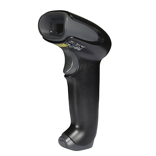
В этом обзоре рассмотрим самую популярную модель этого бренда — Honeywell (Metrologic) Voyager 1450g, его характеристики, сферы использования и особенности настройки.
Настроим и подключим сканер Honeywell за 1 час.
Оставьте заявку и получите консультацию.
Honeywell 1450g: официальный сайт производителя
Русскоязычный ресурс компании находится по адресу www.honeywell.ru. Во вкладке «Продукция и технологии» перечислены все решения компании, структурированные по категориям: аэрокосмическая техника, промышленная безопасность, решения для зданий и др.
В разделе «Автоматическая идентификация и сенсорный контроль» представлено несколько видов сканеров: ручные, стационарные, промышленные, компактные, для медицины и т. д. Сканер шк Honeywell 1450g относится к категории универсальных, так как подходит для разных задач и сфер бизнеса.
Сферы применения
Считыватель применим для ритейла, сферы услуг и общепита, используется преимущественно в небольших розничных точках со средним клиентопотоком — до 150–200 человек за смену:
- минимаркетах;
- магазинах «у дома»;
- аптеках;
- бутиках;
- павильонах в торговых центрах (одежда, обувь и др.);
- столовых, кафе.
Устройство умеет считывать любые линейные и двумерные коды, в том числе PDF417 на алкогольной продукции и DataMatrix на всех остальных товарах, подлежащих обязательной маркировке (обувь, табак и др.).
На сегодняшний день Voyager 1450g уже снят с производства, вместо него на рынке появилась усовершенствованная модификация 1450gHR. Тем не менее рассматриваемая модель доказала свою эффективность и высокую производительность, поэтому по-прежнему остается в арсенале магазинов и оптовых компаний.
Эксплуатация этого аппарата не требует специальной подготовки. Инструкция к сканеру Honeywell 1450g на русском размещена на официальном сайте изготовителя: «Продукция» → «Сканеры» → «Универсальные» → Voyager 1450g. Открыть вкладку «Документы» и выбрать нужный файл. Все инструкции и руководства на сайте доступны для бесплатного скачивания.
Преимущества
Honeywell Metrologic (Voyager) 1450g — недорогой проводной сканер (фотосканер, имиджер) для многоплоскостной обработки 1D- и 2D-штрихкодов. Основные преимущества модели:
- считывание любых линейных и самых распространенных двумерных кодов, в том числе низкого качества (поврежденных, загрязненных, выцветших и т. д.);
- возможность считывания кодов с экранов мобильных устройств, ноутбуков и купонов;
- универсальность за сравнительно низкую стоимость (считыватель подходит для решения разных торговых и учетных задач в коммерческих и бюджетных учреждениях);
- работа с ЕГАИС, «Меркурий», «Честный ЗНАК».
При необходимости пользователь может расширить возможности сканера с помощью дополнительного ПО и лицензий.
Описание
Voyager 1450g совместим с любыми кассами, ПК и смартфонами. Для интеграции с управляющим устройством можно использовать разъем USB, RS-232, RS-485 или разрыв клавиатуры. Характеристики сканера:
- максимальное расстояние считывания — 55 см;
- скорость считывания — 10 скан/мин;
- подключение к ПК — проводное;
- класс защиты — IP40;
- вес — 130 г.
При больших объемах продаж сканер удобнее использовать стационарно, зафиксировав его на подставке. Сканирование возможно под разными углами.
Работа осуществляется в двух режимах: ручной — оператор начинает процесс, нажимая на кнопку, презентационный — пользователь направляет луч на этикетку.
Имиджер можно применять в сложных складских условиях при температуре от 0 до 40 °С. Корпус выполнен из ударопрочного пластика и выдерживает до 30 падений с высоты 1,5 м.
Особенности применения
Видоискатель проецирует направляющий луч, который должен попадать на центр изображения. При этом сам сканер можно держать под любым углом по отношению к этикетке. Удерживая устройство над штрихкодом, пользователь нажимает на кнопку — характерный сигнал проинформирует его об успешном считывании.
Чтобы обеспечить правильную обработку, рекомендуется держать аппарат ближе к маленьким штрихкодам и дальше от крупных. Для сканирования ламинированных этикеток следует зафиксировать фотосканер под небольшим углом.
Metrologic 1450g представлен двумя модификациями — 1450g2D и 1450g1D. Первый может обрабатывать все виды штрихкодов, второй — исключительно линейные.
Мы готовы помочь!
Задайте свой вопрос специалисту в конце статьи. Отвечаем быстро и по существу. К комментариям
Honeywell 1450g: инструкция по подключению
ОС на ПК или POS-системе должна «увидеть» подключенный считыватель. Для этого необходимо скачать драйвер для Honeywell 1450g на сайте разработчика. Прежде чем рассмотреть эту процедуру, узнаем, какие способы подключения доступны.
Как подсоединить сканер к компьютеру
Manual Honeywell 1450g представляет собой краткую инструкцию по подготовке аппарата к эксплуатации. В инструкции сказано, что Voyager поддерживает следующие типы подключения:
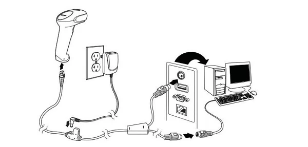
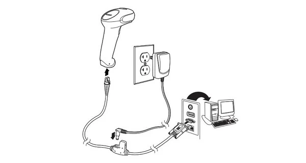
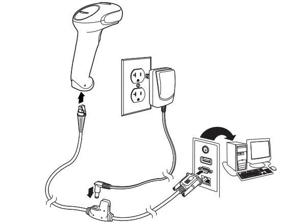
- Разрыв клавиатуры (RS/2). Взаимодействие устройств осуществляется с помощью специального разветвленного шнура. Одна ветка подсоединяется к клавиатуре, вторая — к компьютеру. При этом сам считыватель должен быть подключен к сети с помощью блока питания. Этот вариант актуален для кассовых узлов и рабочих мест, где требуется подвести большое количество периферии.

- RS-232 (COM). Это самый популярный вариант для POS-периферии. Основное преимущество — надежность даже при больших нагрузках. Недостаток — требуется постоянное электропитание.

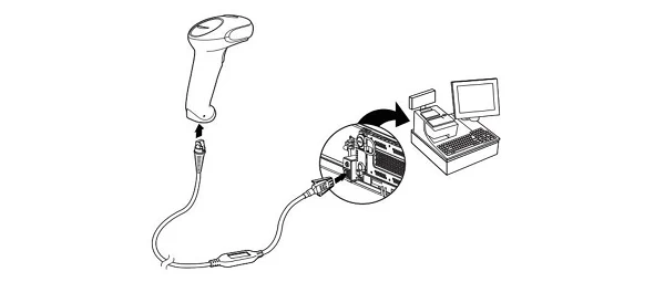
- IBM-46xx (RS-485) — для POS-систем International Business Machines.

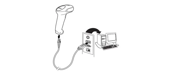
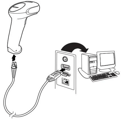
- USB (Hid Pos). Подходит для всех современных касс и не требует подсоединения считывателя к блоку питания.

Поддержка опции Powerlink Cables позволяет легко и безопасно поменять кабели и источники питания без специальных навыков и инструментов.
Какой тип подключения выбрать
К автономным кассам и моноблокам считыватель подключается через USB-разъем. В комплект входит трехметровый шнур, с помощью которого можно разместить устройства в любом удобном месте.
POS-системы обычно интегрируются со сканерами через разъем RS-232. Это самый стабильный вариант, который подходит для торговых точек с высокой проходимостью.
Способ интеграции зависит от ПО. Так, если на компьютере стоит «1С», лучшим выбором будет RS-232 (если этот порт — в наличии), так как с ним совместима бесплатная компонента, встроенная в ПО для автоматизации деятельности предприятия.
Если требуется выводить штриховые коды в Блокнот или систему товарного учета, используется соединение через разрыв клавиатуры.
Подскажем решение проблемы!
Оставьте заявку и получите консультацию в течение 5 минут.
Где скачать драйвер Honeywell 1450g
Актуальные прошивки Honeywell 1450g (firmware) и драйверы доступны на англоязычном веб-ресурсе разработчика. Доступ к файлам открывается после создания личного аккаунта на странице FTP-сервера. В форме регистрации необходимо ввести имя, фамилию и e-mail. Далее пользователь должен придумать пароль и подтвердить его (на указанный почтовый ящик приходит одноразовый код).
Загрузка программ
После создания учетной записи можно зайти в личный кабинет, используя e-mail и указанный при регистрации пароль, и бесплатно скачать нужные драйверы. После авторизации система автоматически перенаправляет пользователя на страницу с ПО. После ознакомительного текста (на английском языке) находится каталог с папками, в которых размещены дистрибутивы. Поиск программы предполагает следующий порядок действий:
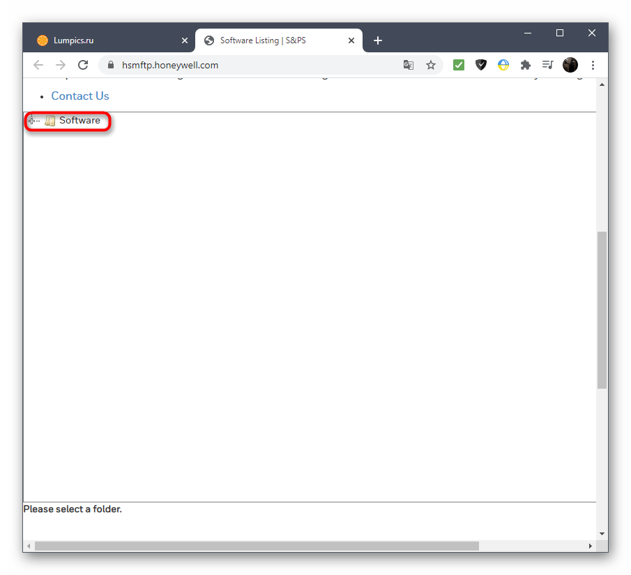
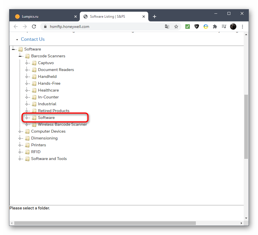
- Нажать на папку Software в левом столбце каталога — отобразится перечень папок с программами для разных аппаратных решений Ханивел.
- Выбрать раздел Barcode Scanner — откроется актуальный список папок с программами.
- Кликнуть по каталогу Drivers.
Здесь появятся все доступные прошивки и утилиты, пользователю останется только выбрать нужную программу, загрузить ее на свой ПК и установить, пользуясь подсказками. POS-драйверы (Point Of Service Drivers Suite) предназначены для упрощенной интеграции сканеров с ПК и POS-системами через разные интерфейсы.
Дополнительная утилита TWAIN Image Xpress позволяет считывать коды, просматривать полученные картинки в специальном приложении на ПК, корректировать параметры (цвет, контрастность и т. д.).
Драйвер эмуляции COM-порта Honeywell 1450g
В некоторых торговых организациях рабочее место продавца оснащается обычным компьютером с кассовым ПО и фискальным регистратором. В большинстве новых ПК отсутствует COM-порт (RS-232), поэтому фотосканер подсоединяют посредством USB-разъема. В этом случае при работе с «1С» у пользователей появляются проблемы: программа не видит считыватель, штрихкоды не отображаются в редакторе и т. д.
Для решения этой проблемы необходимо установить специальный драйвер Honeywell 1450g для эмуляции COM-порта. При подсоединении по USB устройство будет «имитировать» (эмулировать) COM-интерфейс и позволит выполнить пользовательские настройки в режиме эмуляции. ОС и «товароучетка» будут распознавать сканер как COM-устройство, подключенное через RS-232.
Дистрибутив с драйвером USB Serial Driver (Virtual COM Port driver) доступен для скачивания на портале Ханивелл в разделе Scanning and Mobility. Драйвер COM-порта Honeywell 1450g подходит для любых ОС — Windows 10 и более ранних версий, Linux, MacOC.
После инсталляции — последовательно отсканировать служебные коды, перечисленные в руководстве пользователя, которое поставляется в комплекте с имиджером. В результате в Диспетчере устройств появляется виртуальный COM-интерфейс, на котором и будет работать фотосканер Metrologic.
Утилита EZConfig for Scanning
Программа ускоряет и упрощает работу со сканером. Система самостоятельно обнаруживает имиджер, независимо от выбранного режима работы, в том числе при использовании разрыва клавиатуры (этот вариант пользователи выбирают чаще всего). С помощью этой программы легко менять параметры и перепрошивать устройство в соответствии с текущими задачами, проводить диагностику сбоев и устранять системные ошибки.
Штрих-коды для программирования Honeywell 1450g
В краткой инструкции от производителя приведен список штриховых кодов, с помощью которых легко настроить сканер Honeywell 1450g под любые задачи. Для начала требуется сбросить заводские параметры, отсканировав следующий код:

В любой момент пользователю доступен сброс Honeywell 1450g на заводские настройки:

Штрих коды для дальнейшего программирования сканера Honeywell 1450g выбираются с учетом способа интеграции. Для USB необходимо перевести устройство в режим Hid Pos:

Перевод в режим разрыва клавиатуры:

Интерфейс RS-485 применим только для POS-систем IBM:

Перевод Honeywell 1450g в режим эмуляции COM-порта:

Настройка разделительной полосы (дополнительный элемент в 1D-штрихкодах):

Далее рекомендуется зайти в Диспетчер устройств на компьютере и посмотреть, отобразился ли в каталоге новое с интерфейсом COM.
Если применяется режим разрыва клавиатуры, нужны дополнительные настройки — добавление суффикса и префикса для удобного ввода расшифрованных кодов в текстовые редакторы, «1С» и иные системы товароучета.
При сканировании разных этикеток пользователю приходится каждый раз открывать окно ввода штрихкода кнопкой F1. Префикс позволяет избежать этого и сэкономить время, запуская новое окно автоматически. Для добавления префикса необходимо последовательно отсканировать следующие коды:
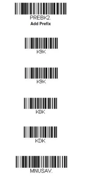
Суффикс возврата каретки Honeywell 1450g обеспечивает автоматический перевод курсора на строку ниже — оператору не приходится нажимать Enter после каждого считывания этикетки. Опция добавляется следующим кодом:
Включение функции Control обеспечивает корректную передачу непечатаемых знаков:

Если предполагается работать с маркированными товарами, нужно включить режим считывания двумерного матричного кода. Настройка DataMatrix Honeywell 1450g одинаковая для всех способов подключения:

Для работы на предприятиях общепита рекомендуется активировать опцию непрерывного сканирования, которая облегчает процесс распознавания штрихкодов с чеков заказа:

Изначально сканер функционирует в режиме «Ручной запуск», считывая коды после нажатия на кнопку. Чтобы перевести устройство в режим презентации, отсканируйте картинку:

Возврат к ручному запуску:

На этом первичные пользовательские настройки завершены. Расширенная инструкция по программированию Honeywell 1450g размещена на интернет-ресурсе компании-изготовителя.
Настройка Honeywell 1450g в 1С
Если фотосканер подключается к компьютеру через COM-порт или клавиатурный разрыв, как правило, не возникает никаких сложностей при интеграции с «1С». Оба этих режима поддерживает драйвер для Honeywell 1450g, который встроен во все конфигурации «1С:Предприятие».
Драйвер имеет двухкомпонентную структуру: интеграционная компонента присутствует в составе «Библиотеки подключаемого оборудования» (БПО), а основная поставка Frontol Driver Unit доступна для скачивания на сайте Ханивел. Если считыватель подсоединяется по USB, потребуется еще и драйвер эмуляции COM-порта.
Перед эксплуатацией рекомендуется проверить работоспособность устройства с помощью Блокнота. При считывании этикетки в редакторе отображается расшифрованная информация в виде числового значения (для линейных кодов) или ссылки (для двумерных). После этого можно перейти к интеграции с товароучетным ПО:
- Зайти в «1С».
- В разделе «Торговое оборудование» открыть вкладку «Подключение», выбрать пункт «Сканеры» и нажать клавишу «Добавить».
- Зайти в меню добавления новой позиции, ввести наименование и модель считывателя.
- Сформировать группу пользователей, открыть для них доступ к сканеру и подтвердить операцию кнопкой ОК.
- В нижней части страницы нажать кнопку проверки — появится уведомление об успешном добавлении оборудования.
- Зайти в раздел «Параметры» → «Драйвер» → «Поиск оборудования» — в каталоге отображается новый Image-сканер с названием интерфейса.
Чтобы проверить корректность взаимодействия сканера и «1С», следует создать документ «Поступление товаров и услуг» и ввести туда позиции с помощью сканера. В карточке продукта штрихкод будет отображаться автоматически.
Не решили проблему самостоятельно? Оставьте заявку специалисту!
Оставьте заявку и получите консультацию в течение 5 минут.

Александр Киреев
Эксперт отдела автоматизации и развития бизнеса Online-kassa.ru. Бизнес-тренер и аналитик, отвечает за работу с ключевыми клиентами.
Оцените, насколько полезна была информация в статье?
Наш каталог продукции
У нас Вы найдете широкий ассортимент товаров в сегментах
кассового, торгового, весового, банковского и офисного оборудования.
Посмотреть весь каталог
Содержание
- Выбор варианта подключения
- Настройка Honeywell Voyager 1450g при первом подключении
- Решение популярных ошибок при сканировании
- Проверка сканера в «Диспетчере устройств»
- Загрузка драйвера для настройки Honeywell Voyager 1450g
- Интеграция Honeywell Voyager 1450g в 1С
- Вопросы и ответы
Выбор варианта подключения
После приобретения сканера Honeywell Voyager 1450g у пользователя, производящего подключение устройства, появляется возможность выбрать один из четырех разных типов соединения с компьютеров. Предлагаем вкратце остановиться на каждом из них, чтобы вы могли определить, какой рабочий режим подходит для торговой точки или персонального компьютера.
- При отсутствии USB-портов или с целью их экономии можно выбрать режим разрыва клавиатуры под названием PS/2. В таком случае сканер в обязательном порядке подключается к электросети при помощи идущего в комплекте адаптера, одна ветка PS подсоединяется к системному блоку, а вторая — направляется к клавиатуре. Этот режим имеет свои особенности сканирования, при которых данные сразу же отправляются в область курсора, что совместимо с любой используемой кассовой программой или софтом учета товарных единиц.
- Если компьютер довольно старый и на нем есть COM-порт, можно использовать его, чтобы подключить Honeywell Voyager 1450g. Тогда понадобится использовать сетевой адаптер, а также загрузить драйверы с официального сайта или диска, идущего в комплекте. Преимущество этого режима тоже заключается в разгрузке USB-портов, но главная проблема — отсутствие COM-портов в современных компьютерах.
- Третий режим самый нераспространенный, поскольку используется только для интеграции с IBM. В Этом случае использован тип подключения RS485, соответственно, отсутствующий в обычных компьютерах. Скорее всего, интеграция с POS-оборудованием производиться не будет, поэтому мы не останавливаемся на детальном разборе этого типа соединения.
- Режим, который подходит всем компьютерам, имеющим в запасе хотя бы один свободный USB-порт, поддерживается всеми современными ККТ. Он не требует подключения сканера к системе питания, а данные о сканировании вводятся сразу же в то поле, куда пользователь установил указатель.


Это все типы подключения к компьютеру, которые может использовать Honeywell Voyager 1450g. Под каждым из них мы оставили схематическое обозначение типа соединения, чтобы у вас не возникало вопросов с тем, куда относится какая линия и нужно ли вообще подключать основное питание. Вне зависимости от выбранного режима инструкция по настройке сканера будет актуальной, но разделы, посвященные его проверке в ОС и использованию ПО для настройки относятся только к Windows, что понадобится учитывать при выполнении этих инструкций.
В комплекте с рассматриваемым сканером должно идти руководство пользователя, где собраны все актуальные коды, относящиеся к общим и продвинутым настройкам данного оборудования. В нашей инструкции мы затронем только те, которые необходимо считать в обязательном порядке, приведя тем самым устройство в рабочее состояние. Заранее подключите его к компьютеру одним из методов и убедитесь, что сканер включен.
- Наведите его на каждый из следующих кодов для сканирования. Первый отвечает за удаление всех установленных пользователем параметров, что нужно сделать для сброса изменений, которые могли активироваться при первоначальном включении или тестировании Honeywell Voyager 1450g.
- Следующий код активирует заводские настройки, возвращая сканер в исходное состояние. Это нужно сделать обязательно даже после сброса пользовательских параметров, чтобы не возникло проблем с дальнейшей настройкой.
- Сразу же внесите в устройство префикс, предназначенный для упрощения задачи сканирования. Если его не использовать, каждый раз придется нажимать клавишу F1, вызывая тем самым строку считывания. У этого префикса есть разные условия и параметры, описанные в руководстве пользователя. Ознакомиться с ними вы сможете в PDF-документе, ссылка на который есть в конце данной инструкции.
- Суффикс отвечает за отмену нажатия клавиши Enter после завершения сканирования. Теперь не придется подтверждать его вручную, если вы используете эту настройку.
- В завершение отсканируйте штрих-код, который подходит абсолютно для всех режимов и нужен только в том случае, если вы собираетесь работать с DataMatrix, что обносится маркированным товарам и другим похожим продуктам.


Как и обещали, оставляем ссылку на официальный PDF-файл от разработчиков на английском языке, в котором собрана перечень всех штрих-кодов, относящихся к программированию Honeywell Voyager 1450g. Там вы найдете разновидности префиксов и сможете активировать другие непопулярные функции, если это требуется. Ознакомьтесь и с информацией о том, как производить выключение определенных режимов, если они случайно были добавлены.
Руководство пользователя Honeywell Voyager 1450g в PDF
Решение популярных ошибок при сканировании
Практически все ошибки при сканировании через Honeywell Voyager 1450g решаются путем перепрограммирования устройства все те ми же штрих-кодами из руководства пользователя, которое мы оставили выше. Однако хотелось бы отдельно упомянуть две самые распространенные проблемы и предоставить коды для их быстрого исправления.
- Если при сканировании 7-значных кодов, к которым относятся и импортные марки сигарет, программа автоматически добавляет в начале ноль, что связано со стандартом восьми знаков, сам товар не будет найден в установленной базе. Это значит, что нужно отключить автозаполнение. Для этого отсканируйте приведенный далее код.
- Вторая проблема — обработка акцизных марок, при которой вместо нужного кода появляется текст ошибки или непонятный набор символов. Это возникает из-за включенного режима DataMatrix, который может и не использоваться. Он отключается точно так же — сканированием специального штрих-кода, изображение которого мы представляем ниже.


Проверка сканера в «Диспетчере устройств»
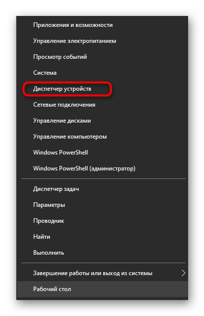
В качестве проверки правильности настройки Honeywell Voyager 1450g отметим его поиск в «Диспетчере устройств» операционной системы. Если вы не знаете, как переходить в это меню, ознакомьтесь со статьей от другого нашего автора по ссылке ниже.
Подробнее: Открываем «Диспетчер устройств» в Windows 10
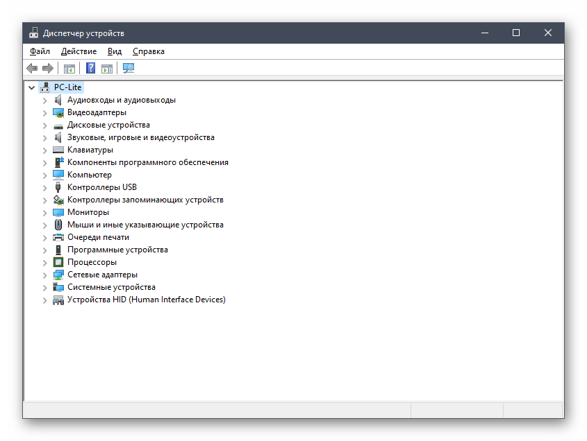
В открывшемся меню вам понадобится отыскать раздел с устройствами формата COM. Разверните его и убедитесь в том, что добавленный сканер отображается правильно. Если же его там нет, сканер не отображается в программах и само сканирование просто не происходит, попробуйте инсталлировать драйвер для настройки так, как это будет показано в следующей инструкции.
Загрузка драйвера для настройки Honeywell Voyager 1450g
Руководство по инсталляции драйверов для рассматриваемого сканера необходимо тем пользователям, столкнувшимся с проблемами при обнаружении его в ОС или желающим использовать дополнительные функции, отсутствующие в программированной части, указанной в руководстве пользователя. Для программной настройки устройства используется специальный софт, загружаемый с официального сайта.
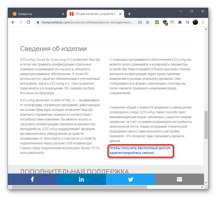
Перейти на официальный сайт Honeywell
- Перейдите по ссылке выше, где сразу приступите к регистрации для получения бесплатного доступа ко всем файлам устройств от данного производителя. Введите электронный адрес и желаемый пароль, который будет прикреплен к учетной записи.
- Сразу после завершения создания профиля произойдет переход на страницу загрузки софта, где нужно развернуть корневую папку.
- В ней выберите первую директорию «Barcode Scanners» и дважды кликните по ней для открытия.
- Отыщите раздел «Software».
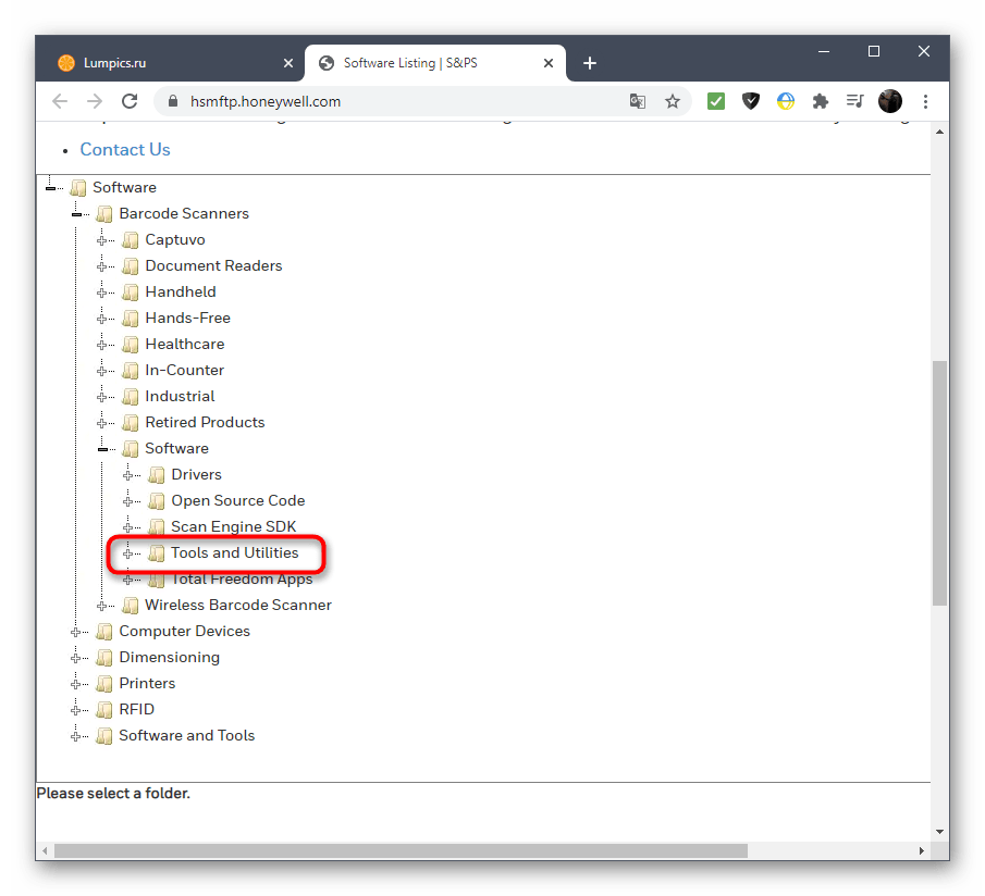
- В нем вас интересует «Tools and Utilities».
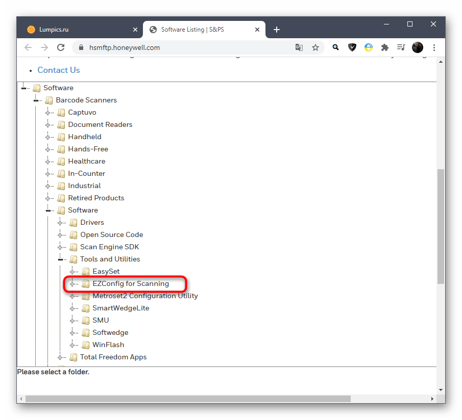
- Программа, которая предназначена для настройки Honeywell Voyager 1450g перед сканированием, расположена в папке «EZConfig for Scanning».
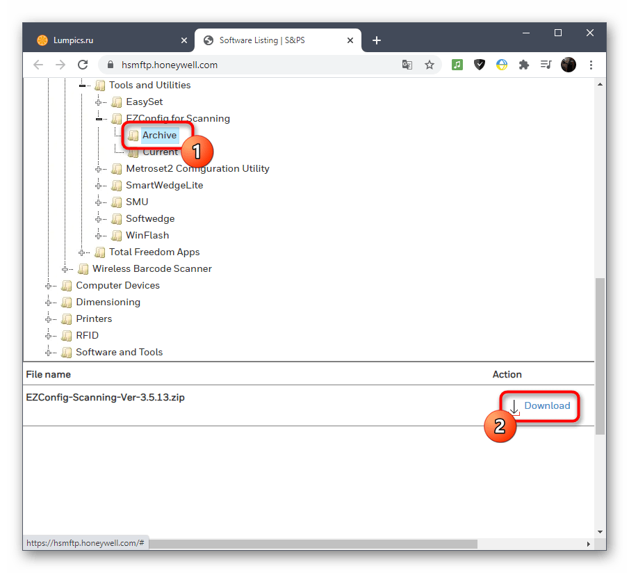
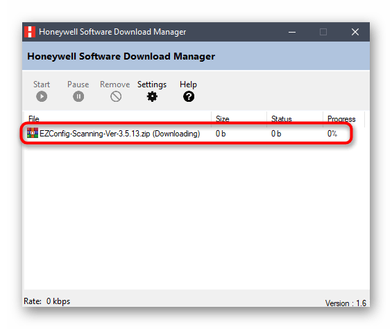
- Выберите вариант распространения через архив и запустите его загрузку. Появится уведомление о том, что сначала понадобится скачать фирменный продукта Software Downloader, с чем необходимо согласиться.
- Установите его стандартным образом и запустите для выполнения дальнейших действий.
- Сразу же начнется скачивание упомянутого архива, что займет определенное время, а после нажмите по нему для открытия.
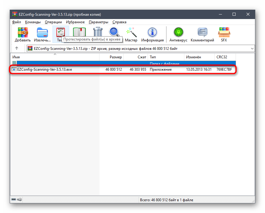
- В архиве находится всего один исполняемый файл, который и нужно запустить.
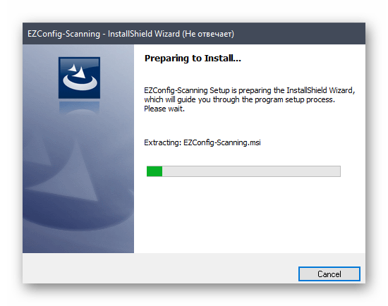
- Подтвердите инсталляцию и выберите место на локальном хранилище, куда хотите добавить все файлы.
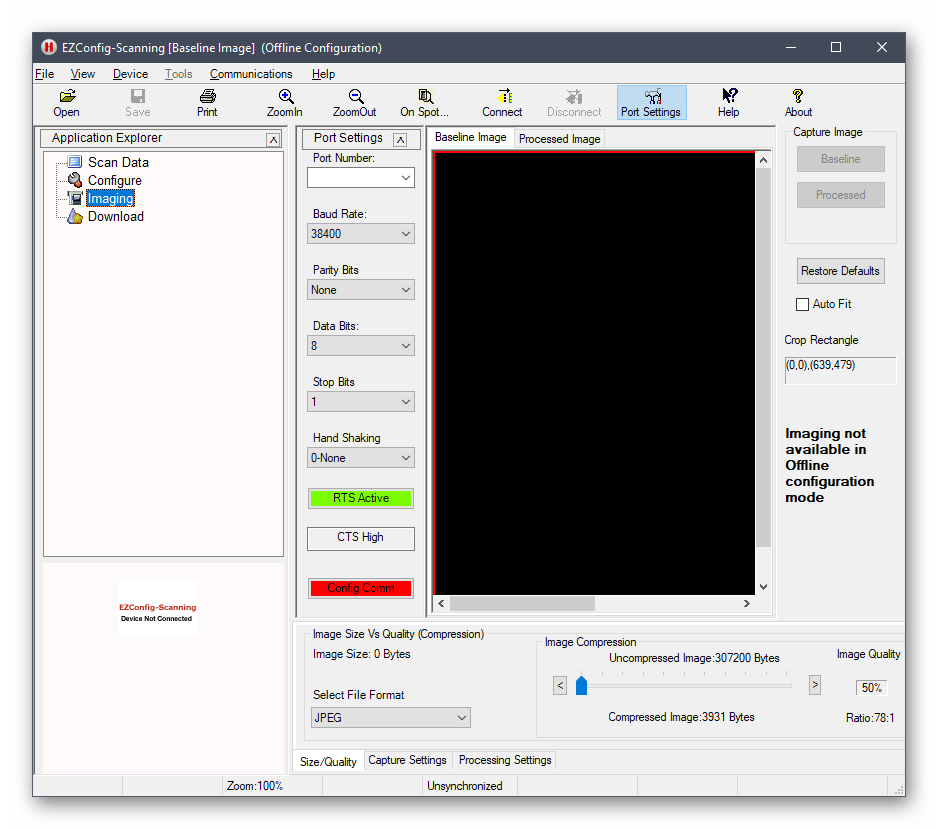
- После запуска EZConfig-Scanning обнаружение устройства обычно выполняется автоматически, если оно уже подключено к компьютеру. В том случае, когда этого не произошло, понадобится нажать на «Connect» и дождаться появления соответствующего уведомления.
- Далее вы можете начать управление настройками сканирования и другими функциями, присутствующими в этом приложении. Не изменяйте стандартные настройки, если не знаете, за что они отвечают и как пользоваться встроенными инструментами.


Интеграция Honeywell Voyager 1450g в 1С
К сожалению, мы не имеем всех технических возможностей для того, чтобы детально разобрать процесс интеграции Honeywell Voyager 1450g для работников с 1С, поэтому мы составили краткую общую инструкцию, примерно описывающую этот процесс. Если вы занимаетесь сканированием товаров через софт от данных разработчиков и используете рассматриваемый сканер, скорее всего, руководство поможет без проблем осуществить подключение и сразу же перейти к работе.

- Необходимые настройки включены в базовую конфигурацию 1С, поэтому запустите программу и перейдите в раздел «Торговое оборудование».
- Выберите раздел «Подключение и настройка».
- Приступайте к добавлению нового сканера, выбрав соответствующий пункт.
- Укажите группу пользователей, которым хотите разрешить управление устройством.
- Проверьте подключение устройства в новом окне настроек, предварительно подключив его к компьютеру.
- После этого можете перейти к «Параметры» и выбрать раздел «Драйверы сканера». Посмотрите, появилось ли там новое оборудование.
- В качестве проверки используйте любую форму поступления товара, сканируя штрих-коды при помощи Honeywell Voyager 1450g.
 По умолчанию для сканера включен интерфейс USB настроенный в разрыв клавиатуры. В подавляющем большинстве для настройки сканера с новыми конфигурациями 1С этот режим подходит. Но иногда случаются ситуации когда настройки по умолчанию, не совсем подходят для старых конфигураций. Так например, сканер в разрыве клавиатуры с настройками по умолчанию некорректно отрабатывал штрих-коды в конфигурации Управление Аптекой.
Для настройки сканера требовалось установить преффиксы и суффиксы, и установить их в значение +++. Таким образом после сканирования мы должны были получить штрихкод вида
+++4121232412124+++
Ниже приведу порядок действий ля настройки сканера.
Скачиваем руководство по программированию сканеров Metrologic.
- Переводим сканер в режим программирования. Сканируем штрих-код со страницы 4.
- Устанавливаем 1-ый префикс. Сканируем 1-ый штрих-код со страницы 15.
- Вводим шестнадцатеричный код необходимого нам символа. Нужный мне символ + имеет код 043. Таблица кодов находится на страницах 30-32.
Повторяем пункты 2 и 3, три раза, так как нам необходимо 3 символа перед штрих-кодом. - Выходим из режима программирования сканируя штрих-код с 4-ой страницы. Таким образом мы закончили настройку префиксов. Суффиксы настраиваются по аналогии.
- Переводим сканер в режим программирования. Сканируем штрих-код со страницы 4.
- Устанавливаем 1-ый префикс. Сканируем 1-ый штрих-код со страницы 18.
- Вводим шестнадцатеричный код необходимого нам символа. Нужный мне символ + имеет код 043. Таблица кодов находится на страницах 30-32.
Повторяем пункты 2 и 3, три раза, так как нам необходимо 3 символа перед штрих-кодом. - Выходим из режима программирования сканируя штрих-код с 4-ой страницы.
Оборудование Торговля
- Page 1
Voyager XP™ 1470g/1472g Series Area-Imaging Scanner User Guide… - Page 2
Disclaimer Honeywell International Inc. (“HII”) reserves the right to make changes in specifications and other information contained in this document without prior notice, and the reader should in all cases consult HII to determine whether any such changes have been made. The information in this publication does not represent a commitment on the part of HII. -
Page 3: Table Of Contents
TABLE OF CONTENTS Customer Support ……………………xiii Technical Assistance ………………….xiii Product Service and Repair ………………..xiii Limited Warranty ……………………xiii Chapter 1 — Get Started ………………1 About This Manual……………………. 1 Unpack Your Device……………………1 Connect the Device……………………2 Connect with USB……………………
- Page 4
® Verifone Ruby Terminal Default Settings ……………..16 ® Gilbarco Terminal Default Settings………………17 Honeywell Bioptic Aux Port Configuration…………….17 © Datalogic™ Magellan Bioptic Aux Port Configuration ……….17 NCR Bioptic Aux Port Configuration………………18 Wincor Nixdorf Terminal Default Settings……………..18 Wincor Nixdorf Beetle™ Terminal Default Settings…………19 Wincor Nixdorf RS232 Mode A………………..19… - Page 5
Scanner-Bioptic Packet Mode………………35 Scanner-Bioptic ACK/NAK Mode………………35 Scanner-Bioptic ACK/NAK Timeout …………….36 Chapter 3 — Cordless System Operation ………….37 How the Cordless Charge Base/Access Point Works………….37 Link the Scanner to a Charge Base………………37 Link the Scanner to an Access Point ………………38 Replace a Linked Scanner ………………….39 Communication Between the Cordless System and the Host………………………39 Program the Scanner and Base or Access Point ………….40… - Page 6
Error Indicators……………………..47 Beeper Pitch — Base Error………………..47 Number of Beeps — Base Error ………………47 Scanner Report……………………..48 Scanner Address ……………………..48 Base or Access Point Address ………………..48 Scanner Modes……………………..48 Charge Only Mode ……………………49 Linked Modes …………………….49 Unlink the Scanner……………………50 Override Locked Scanner………………..50 Out-of-Range Alarm……………………50 Alarm Sound Type …………………….51 Scanner Power Time-Out Timer…………………52… - Page 7
Bluetooth HID Keyboard Connect……………….64 Virtual Keyboard……………………66 Bluetooth HID Keyboard Disconnect…………….66 Bluetooth Serial Port — PCs/Laptops…………….66 PDAs/Mobility Systems Devices ………………66 Change the Scanner’s Bluetooth PIN Code …………..67 Minimize Bluetooth/ISM Band Network Activity …………67 Auto Reconnect Mode ………………….67 Maximum Link Attempts ………………..68 Relink Time-Out ……………………69 Bluetooth/ISM Network Activity Examples…………..69 Host Acknowledgment …………………..70… - Page 8
Presentation Centering…………………..79 In-Stand Sensor Mode…………………..81 Poor Quality Codes……………………82 Poor Quality 1D Codes ………………….82 Poor Quality PDF Codes …………………82 ® CodeGate ……………………….83 Mobile Phone Read Mode ………………….83 Hands Free Time-Out…………………….83 Reread Delay……………………..84 User-Specified Reread Delay ………………..84 2D Reread Delay ……………………84 Character Activation Mode ………………….85 Activation Character ………………….85 End Character Activation After Good Read…………..86 Character Activation Timeout ………………86… - Page 9
Suffix Selections………………………95 Function Code Transmit ………………….96 Intercharacter, Interfunction, and Intermessage Delays ……….96 Intercharacter Delay………………….96 User Specified Intercharacter Delay …………….97 Interfunction Delay…………………..97 Intermessage Delay ………………….98 Chapter 6 — Data Format …………….99 Data Format Editor Introduction ……………….99 Show Data Format ……………………100 Add a Data Format……………………100 Other Programming Selections ………………101 Terminal ID Table ……………………102 Data Format Editor Commands ………………102… - Page 10
Code 93 Code Page ………………….125 Straight 2 of 5 Industrial (three-bar start/stop)…………125 Straight 2 of 5 IATA (two-bar start/stop)…………….. 126 Matrix 2 of 5 ……………………..127 Code 11……………………….128 Code 128 ……………………….129 ISBT 128 Concatenation ………………..129 Code 128 Code Page …………………. - Page 11
QR Code Append…………………….153 QR Code Page ……………………154 Data Matrix ……………………..154 Data Matrix Code Page…………………155 MaxiCode……………………….155 Aztec Code ………………………156 Aztec Code Page …………………….158 Chinese Sensible (Han Xin) Code………………158 Postal Codes — 2D……………………159 Single 2D Postal Codes:………………..159 Combination 2D Postal Codes: ………………160 Postal Codes — Linear ………………….163 China Post (Hong Kong 2 of 5)………………163 Korea Post……………………..164… - Page 12
Menu Commands ……………………175 Chapter 10 — Product Specifications…………197 Voyager XP 1470g Scanner Product Specifications ……….197 Voyager XP 1472g Cordless Scanner Product Specifications…….. 198 CCB01-010BT-V1N Charge Base Product Specifications……..199 Depth of Field Charts ………………….200 Typical Performance ………………….200 Guaranteed Performance ……………….. - Page 13
2D Symbologies ……………………214 Postal Symbologies ………………….215 ASCII Conversion Chart (Code Page 1252) …………..216 Lower ASCII Reference Table………………..217 ISO 2022/ISO 646 Character Replacements …………..220 Keyboard Key References…………………..223 Sample Symbols………………..225 Programming Chart ………………227 Voyager 1470/1472 User Guide… - Page 14
Voyager 1470/1472 User Guide… -
Page 15: Customer Support
Honeywell International Inc. provides service for all of its products through service centers throughout the world. To obtain warranty or non-warranty service, return your product to Honeywell (postage paid) with a copy of the dated purchase record. To learn more, go to www.honeywellaidc.com…
- Page 16
Voyager 1470/1472 User Guide… -
Page 17: Chapter 1 — Get Started
PDF and 2 dimensional bar codes can only be read by model 147Xg2D and cannot be read by model 147Xg1D. Honeywell bar code scanners are factory programmed for the most common ter- minal and communications settings. If you need to change these settings, pro- gramming is accomplished by scanning the bar codes in this guide.
-
Page 18: Connect The Device
Connect the Device Connect with USB A scanner or a cordless base can be connected to the USB port of a computer. 1. Connect the appropriate interface cable to the device first, then to the com- puter. Corded Voyager XP 1470g USB Connection: CCB01-010BT-V1N Base USB…
-
Page 19: Connect With Keyboard Wedge
The unit defaults to a USB PC Keyboard. Refer to page 14 for other USB terminal settings. For additional USB programming and technical information, refer to “USB Applica- tion Note,” available at www.honeywellaidc.com. Connect with Keyboard Wedge A scanner or cordless base can be connected between the keyboard and PC as a “keyboard wedge,”…
-
Page 20: Connect With Rs232 Serial Port
CCB01-010BT-V1N Base CCB01-010BT-V1N Base Keyboard Wedge Connection: Keyboard Wedge Connection: Note: The power supply must be ordered separately, if needed. 3. If you are connecting a CCB01-010BT-V1N Base, make sure the cables are secured in the wireways in the bottom of the cordless base and the base sits flat on a horizontal surface.
- Page 21
Corded Voyager XP 1470g RS232 Serial Port Connection: CCB01-010BT-V1N Base RS232 Serial Port Connection: Note: The power supply must be ordered separately, if needed. 1. If you are connecting a CCB01-010BT-V1N Base, make sure the cables are secured in the wireways in the bottom of the cordless base and the base sits flat on a horizontal surface. -
Page 22: Connect With Rs485
Connect with RS485 A scanner or cordless base can be connected for an IBM POS terminal interface. 1. Connect the appropriate interface cable to the device, then to the computer. Corded Voyager XP 1470g RS232 Serial Port Connection: CCB01-010BT-V1N Base RS485 Connection: 2.
-
Page 23: Mount A Ccb01-010Bt-V1N Charge Base
Mount a CCB01-010BT-V1N Charge Base 2.36 in. 2.8 in. 59.84mm 72.1mm 3.35 in. 8×32 thread 85.09mm x .39 in. (10mm) deep Reading Techniques The scanner has a view finder that projects a bright red aiming dot that corre- sponds to the scanner’s horizontal field of view. The aiming dot should be centered over the bar code, but it can be positioned in any direction for a good read.
-
Page 24: Menu Bar Code Security Settings
Menu Bar Code Security Settings Honeywell scanners are programmed by scanning menu bar codes or by sending serial commands to the scanner. If you want to restrict the ability to scan menu codes, you can use the Menu Bar Code Security settings. Please contact the near-…
-
Page 25: Reset The Custom Defaults
Reset the Custom Defaults If you want the custom default settings restored to your scanner, scan the Activate Custom Defaults bar code below. This is the recommended default bar code for most users. It resets the scanner to the custom default settings. If there are no cus- tom defaults, it will reset the scanner to the factory default settings.
- Page 26
Voyager 1470/1472 User Guide… -
Page 27: Chapter 2 — Program The Interface
CHAPTER PROGRAM THE INTERFACE Introduction This chapter describes how to program your system for the desired interface. Program the Interface — Plug and Play Plug and Play bar codes provide instant scanner set up for commonly used inter- faces. Note: After you scan one of the codes, power cycle the host terminal to have the interface in effect.
-
Page 28: Laptop Direct Connect
Laptop Direct Connect For most laptops, scanning the Laptop Direct Connect bar code allows operation of the scanner in parallel with the integral keyboard. The following Laptop Direct Connect bar code also programs a carriage return (CR) suffix and turns on Emu- late External Keyboard (page 28).
-
Page 29: Rs485 Packet Mode
IBM Port 5B Interface IBM Port 17 Interface IBM Port 9B HHBCR-2 Interface Each bar code above also programs the following suffixes for each symbology: Symbology Suffix Symbology Suffix EAN 8 Code 39 00 0A 0B EAN 13 Interleaved 2 of 5 00 0D 0B UPC A Code 128 *…
-
Page 30: Usb Ibm Surepos
RS485 Packet Length If you are using Packet mode, you can specify the size of the data “packet” that is sent to the host. Scan the Packet Length bar code, then the packet size (from 20 — 256) from the Programming Chart, then Save.
-
Page 31: Usb Hid
Scan the following code to program the scanner to emulate a regular RS232-based COM Port. If you are using a Microsoft® Windows® PC, you will need to download a driver from the Honeywell website (www.honeywellaidc.com). The driver will use the next available COM Port number. Apple® Macintosh computers recognize the scanner as a USB CDC class device and automatically uses a class driver.
-
Page 32: Ack/Nak Mode
ACK/NAK Mode ACK/NAK Mode On * ACK/NAK Mode Off Remote MasterMind™ for USB When using a USB interface, you may wish to configure your scanner to communi- cate with Remote MasterMind Scanner Management Software (ReM). Scan the ReM On bar code to communicate with ReM. To disable this capability, scan ReM Off.
-
Page 33: Gilbarco ® Terminal Default Settings
Gilbarco Settings Honeywell Bioptic Aux Port Configuration Scan the following Plug and Play code to program the scanner for a Honeywell bioptic scanner auxiliary port configuration. This bar code sets the baud rate to 38400 bps and the data format to 8 data bits, no parity, 1 stop bit.
-
Page 34: Ncr Bioptic Aux Port Configuration
NCR Bioptic Aux Port Configuration Scan the following Plug and Play code to program the scanner for an NCR bioptic scanner auxiliary port configuration. The following prefixes are programmed for each symbology: Symbology Prefix Symbology Prefix UPC-A Interleaved 2 of 5 UPC-E Code 128 GS1 DataBar…
-
Page 35: Wincor Nixdorf Beetle™ Terminal Default Settings
Wincor Nixdorf Beetle™ Terminal Default Settings Scan the following Plug and Play code to program the scanner for a Wincor Nixdorf Beetle terminal. This bar code sets the baud rate to 115200 bps and the data for- mat to 8 data bits, no parity, 1 stop bit. The following prefixes are programmed for each symbology: Symbology Prefix…
-
Page 36: Keyboard Country Layout
Keyboard Country Layout If your interface is USB Keyboard or Keyboard Wedge, your keyboard layout default is a US keyboard. To change this layout, refer to the chart below for your keyboard country. Scan the appropriate bar code below to change the layout. By default, national character replacements are used for the following characters: #$@[]^‘{|}~ See ISO 2022/ISO 646 Character Replacements…
- Page 37
Keyboard Countries (Continued) Bulgaria (Cyrillic) Bulgaria (Latin) Canada (French legacy) Canada (French) Canada (Multilingual) Croatia Czech Czech (Programmers) Czech (QWERTY) Czech (QWERTZ) Denmark Dutch (Netherlands) Voyager 1470/1472 User Guide… - Page 38
Keyboard Countries (Continued) Estonia Faroese Finland France Gaelic Germany Greek Greek (220 Latin) Greek (220) Greek (319 Latin) Greek (319) Greek (Latin) Voyager 1470/1472 User Guide… - Page 39
Keyboard Countries (Continued) Greek (MS) Greek (Polytonic) Hebrew Hungarian (101 key) Hungary Iceland Irish Italian (142) Italy Japan ASCII Kazakh Kyrgyz (Cyrillic) Voyager 1470/1472 User Guide… - Page 40
Keyboard Countries (Continued) Latin America Latvia Latvia (QWERTY) Lithuania Lithuania (IBM) Macedonia Malta Mongolian (Cyrillic) Norway Poland Polish (214) Polish (Programmers) Voyager 1470/1472 User Guide… - Page 41
Keyboard Countries (Continued) Portugal Romania Russia Russian (MS) Russian (Typewriter) Serbia (Cyrillic) Serbia (Latin) Slovakia Slovakia (QWERTY) Slovakia (QWERTZ) Slovenia Voyager 1470/1472 User Guide… - Page 42
Keyboard Countries (Continued) Spain Spanish variation Sweden Switzerland (French) Switzerland (German) Tatar Turkey F Turkey Q Ukrainian United Kingdom United States (Dvorak) United States (Dvorak left) Voyager 1470/1472 User Guide… -
Page 43: Keyboard Style
Keyboard Countries (Continued) United Stated (Dvorak United States (International) Uzbek (Cyrillic) Keyboard Style This programs keyboard styles, such as Caps Lock and Shift Lock. If you have used Keyboard Conversion settings, they will override any of the following Keyboard Style settings. Default = Regular. Regular is used when you normally have the Caps Lock key off.
-
Page 44: Keyboard Conversion
The Autocaps via NumLock bar code should be scanned in countries (e.g., Ger- many, France) where the Caps Lock key cannot be used to toggle Caps Lock. The NumLock option works similarly to the regular Autocaps, but uses the NumLock key to retrieve the current state of the Caps Lock.
-
Page 45: Control Character Output
Control Character Output This selection sends a text string instead of a control character. For example, when the control character for a carriage return is expected, the output would display [CR] instead of the ASCII code of 0D. Refer to ASCII Conversion Chart (Code Page 1252) on page 216.
-
Page 46: Rs232 Modifiers
Windows Mode Prefix/Suffix The scanner sends characters to a terminal faster. If the terminal drops Turbo Mode: characters, do not use Turbo Mode. Default = Off. Turbo Mode On * Turbo Mode Off Sends numeric characters as if entered from a numeric key- Numeric Keypad Mode: pad.
- Page 47
1200 2400 4800 9600 19200 38400 57,600 * 115,200 Voyager 1470/1472 User Guide… -
Page 48: Rs232 Word Length: Data Bits, Stop Bits, And Parity
RS232 Word Length: Data Bits, Stop Bits, and Parity Data Bits sets the word length at 7 or 8 bits of data per character. If an application requires only ASCII Hex characters 0 through 7F decimal (text, digits, and punctua- tion), select 7 data bits.
-
Page 49: Rs232 Receiver Time-Out
RS232 Receiver Time-Out The unit stays awake to receive data until the RS232 Receiver Time-Out expires. A manual trigger resets the time-out. When an RS232 receiver is sleeping, a charac- ter may be sent to wake up the receiver and reset the time-out. A transaction on the CTS line will also wake up the receiver.
-
Page 50: Rs232 Timeout
RS232 Timeout When using Flow Control with Timeout, you must program the length of the delay you want to wait for CTS from the host. Set the length (in milliseconds) for a time- out by scanning the bar code below, then setting the timeout (from 1-5100 milli- seconds) by scanning digits from the Programming Chart, then scanning Save.
-
Page 51: Scanner To Bioptic Communication
Scanner to Bioptic Communication The following settings are used to set up communication between Honeywell scan- ners and bioptic scanners. Note: The scanner’s baud rate must be set to 38400 and the RS232 timeout must be set to 3000 in order to communicate with a bioptic scanner. See «RS232 Baud Rate» on…
-
Page 52: Scanner-Bioptic Ack/Nak Timeout
Scanner-Bioptic ACK/NAK Timeout This allows you to set the length (in milliseconds) for a timeout for a bioptic scan- ner’s ACK/NAK response. Scan the bar code below, then set the timeout (from 1- 30,000 milliseconds) by scanning digits from the Programming Chart, then scan- ning Save.
-
Page 53: Chapter 3 — Cordless System Operation
CHAPTER CORDLESS SYSTEM OPERATION Note: This chapter applies only to cordless scanning systems. It does not apply to corded scanners. How the Cordless Charge Base/Access Point Works A cordless charge base or an Access Point provides the link between the cordless scanner and the host system.
-
Page 54: Link The Scanner To An Access Point
If the scanner and base have previously been linked, you do not receive any feed- back. If this is the first time that the scanner and base are linked, both devices emit a short chirp when their radios link. At this point, that one scanner is linked to one base.
-
Page 55: Replace A Linked Scanner
Replace a Linked Scanner If you need to replace a broken or lost scanner that is linked to a base or an Access Point, scan the Override Locked Scanner bar code below with a new scanner and place that scanner in the base, or scan the Access Point linking bar code. The locked link will be overridden;…
-
Page 56: Program The Scanner And Base Or Access Point
Program the Scanner and Base or Access Point When using the scanner and charge base or Access Point together as a system, menu parameters and configuration settings are stored in the charge base or Access Point. Therefore, when programming any menu configuration settings, the scanner must be linked to the intended charge base or Access Point.
-
Page 57: Scanner Is Moved Back Into Range
range and you scan a bar code, the scanner issues an error tone indicating no com- munication with the base or Access Point. A cordless charge base can also sound an alarm. Refer to Out-of-Range Alarm. Scanner Is Moved Back Into Range The scanner relinks if the scanner or the base or Access Point have been reset, or the scanner comes back into range.
-
Page 58: Charge Information
Replace it after the battery is unable to hold an adequate charge. • If you are not sure if the battery or charger is working properly, send it to Honeywell International Inc. or an authorized service center for inspection. Refer to Customer Support for additional information.
-
Page 59: Proper Disposal Of The Battery
• Do not disassemble or modify batteries. Caution: Danger of explosion if batteries are incorrectly replaced. Dispose of used batteries according to the recycle program for batteries as directed by the governing agency for the country where the batteries are to be discarded. Proper Disposal of the Battery When the battery has reached the end of its useful life, the battery should be disposed of by a qualified recycler or hazardous materials…
-
Page 60: Base/Access Point Led Sequences And Meaning
Base/Access Point LED Sequences and Meaning The base contains a red LED and the Access Point has a blue LED that indicate the status of the unit and verify its communication with the host system. The base also has a green LED that indicates scanner battery charge condition. Red or Blue LED — Host Communication Red or Blue LED Communication Condition…
-
Page 61: Reset Scanner
Reset Scanner Scanning this bar code reboots the scanner and causes it to relink with the base or Access Point. Reset Scanner Scan While in Base Cradle If you want to be able to scan bar codes while the scanner is in the base cradle, scan the Scanning in Cradle On bar code below.
-
Page 62: Page Mode
When External Power Only is selected, the scanner battery only charges from the base’s external power supply. If there is no external power supply, the scanner bat- tery does not charge. Note: If you are using a cordless charge base in Presentation Mode, External Power Only is the only setting available.
-
Page 63: Page Pitch
Page Pitch When you press the Page button on the base or Access Point, the scanners associ- ated with that base or Access Point will begin beeping (see Page Button). You can set the pitch of the paging beep for each scanner by scanning one of the following bar codes.
-
Page 64: Scanner Report
response to an error. To change the number of error beeps, scan the bar code below and then scan a digit (1-9) bar code and the Save bar code on the Programming Chart. Default = 1. Number of Base Error Beeps/LED Flashes Scanner Report Scan the bar code below to generate a report for the connected scanners.
-
Page 65: Charge Only Mode
Charge Only Mode There may be times when you want to charge your scanner, but not link to the base. For example, if a scanner is linked to an Access Point or other Bluetooth device and you need to charge the scanner, but want to retain your existing link. In order to program the base for Charge Only Mode, you must link a scanner to it.
-
Page 66: Unlink The Scanner
To use a different scanner, you need to unlink the original scanner by scanning the Unlink Scanner bar code. (See Scanner Modes.) Open Link Mode — Single Scanner When newly shipped or defaulted to factory settings, a scanner is not linked to a base or an Access Point.
-
Page 67: Alarm Sound Type
Access Point, when the base or Access Point connects to another scanner, or when the alarm duration expires. To activate the alarm options for the scanner or the base and to set the alarm duration, scan the appropriate bar code below and then set the timeout duration (from 0-3000 seconds) by scanning digits on the Programming Chart, then scanning Save.
-
Page 68: Scanner Power Time-Out Timer
Scanner Alarm Type Scanner Power Time-Out Timer Note: Scanner Power Time-out Timer only applies to cordless systems. It does not apply to corded scanners. When there is no activity within a specified time period, the scanner enters low power mode. Scan the appropriate scanner power time-out bar code to change the time-out duration (in seconds).
-
Page 69: Flexible Power Management
(100%), Medium Power (35%), Medium Low Power (5%), or Low Power (1%). Default = Full Power. * Full Power Medium Power Medium Low Power Low Power Batch Mode Note: Batch Mode is only supported by the Honeywell Charge and Communication Base (CCB) and Honeywell Access Point (AP). Voyager 1470/1472 User Guide…
- Page 70
Batch mode is used to store bar code data when a scanner is out of range of its base or Access Point, or when performing inventory. The data is transmitted to the base or Access Point once the scanner is back in range or when the records are manually transmitted. -
Page 71: Batch Mode Beep
Batch Mode Beep When scanning in Inventory Batch Mode, the scanner beeps every time a bar code is scanned. When Batch Mode Beep is On, you will also hear a click when each bar code is sent to the host. If you do not want to hear these clicks, scan Batch Mode Beep Off.
-
Page 72: Batch Mode Quantity
Batch Mode Quantity When in Batch Mode, you may wish to transmit the number of multiple bar codes scanned, rather than a single bar code multiple times. For example, if you scan three bar codes called XYZ with Batch Mode Quantity Off, when you transmit your data it will appear as XYZ three times.
- Page 73
1. Scan the quantity 0 bar code to change the quantity to 1030. 2. Scan the quantity 0 bar code to change the quantity to 0300. 3. Scan the quantity 1 bar code to change the quantity to 3001. 4. Scan the quantity 0 bar code to change the quantity to 0010. Default = 1. -
Page 74: Batch Mode Output Order
Batch Mode Output Order When batch data is transmitted, select whether you want that data sent as FIFO (first-in first-out), or LIFO (last-in first-out). Default = Batch Mode FIFO. * Batch Mode FIFO Batch Mode LIFO Total Records If you wish to output the total number of bar codes scanned when in Batch Mode, scan Total Records.
-
Page 75: Transmit Records To Host
Transmit Records to Host If you are operating in Inventory Batch Mode Inventory Batch Mode, you must scan the following bar code to transmit all the stored data to the host system. Transmit Inventory Records Batch Mode Transmit Delay Sometimes when accumulated scans are sent to the host system, the transmission of those scans is too fast for the application to process.
-
Page 76: Scanner Name
To put the scanner in multiple scanner mode, scan the bar code below. Once you scan this bar code, the scanner is unlinked from the base or Access Point and must either be placed into the base, or you must scan the Access Point linking bar code in order to relink.
-
Page 77: Application Work Groups
You could assign all the scanners in the retail area to one work group and those in the warehouse to another. Consequently, any desired changes to either the retail or warehouse area would apply to all scanners in that particular work group. Honeywell’s online configuration tool, EZConfig for Scanning (page 168), makes it easy for you to program your system for use with multiple scanners and multiple work groups.
-
Page 78: Application Work Group Selection
Application Work Group Selection This programming selection allows you to assign a scanner to a work group by scanning the bar code below. You may then program the settings (e.g., beeper vol- ume, prefix/suffix, data formatter) that your application requires. Default = Group 0. * Group 0 Group 1 Group 2…
-
Page 79: Reset The Custom Defaults: All Application Work Groups
The scanner can be used either with the charge base, an Access Point, or with other Bluetooth devices. Those devices include personal computers, laptops, PDAs, and Honeywell mobility systems devices. Bluetooth Secure Simple Pairing (SSP) Secure Simple Pairing (SSP) allows you to connect simply and securely to other…
-
Page 80: Bluetooth Hid Keyboard Connect
sion 2.1 or higher. When SSP is on, no PIN is required for pairing. Turn SSP off if you are connecting to a Bluetooth device that is not using a compatible Bluetooth version. Default = Bluetooth SSP On. * Bluetooth SSP On Bluetooth SSP Off Bluetooth HID Keyboard Connect Your scanner can be paired with Bluetooth-capable devices, such as personal com-…
- Page 81
Save Your personal computer, laptop, or tablet should now be paired with the scanner. Once the scanner battery is charged and you have paired it, you may begin scan- ning bar codes. Verify the scanner operation by scanning a bar code from the Sample Symbols in the back of this manual. -
Page 82: Virtual Keyboard
Non-Base BT Connection PDAs/Mobility Systems Devices You may also use the scanner with a PDA or a Honeywell Mobility Systems device. Scan the bar code below and follow the instructions supplied with your Bluetooth device to locate the scanner, and connect with it.
-
Page 83: Change The Scanner’s Bluetooth Pin Code
Change the Scanner’s Bluetooth PIN Code Some devices require a PIN code as part of the Bluetooth security features. Your scanner’s default PIN is 1234, which you may need to enter the first time you con- nect to your PDA or PC. The PIN code must be between 1 and 16 characters. To change the PIN, scan the bar code below and then scan the appropriate numeric bar codes from the Programming…
-
Page 84: Maximum Link Attempts
Event Auto Reconnect On Auto Reconnect Off Base or Access point reset Scanner behaves as if out of range. No attempt to relink made while base (firmware upgrade or power cycle) or Access Point is powered off. Trigger must be pulled to initiate relinking. Scanner power down due to Trigger must be pulled, Access Point linking bar code must be scanned, or the Scanner Power Time-Out Timer…
-
Page 85: Relink Time-Out
Relink Time-Out Relink Time-Out controls the idle time between relink attempts. An attempt to link a scanner to a base or an Access Point typically lasts up to 5 seconds. This is the time when the scanner is actually attempting a contact. Relink Time-Out controls the amount of time, in seconds, that elapses between the end of one connection attempt and the start of the next.
-
Page 86: Host Acknowledgment
Auto Reconnect Mode set to 1 Maximum Link Attempts set to 0 Relink Time-Out set to 10 Scanner Power Time-Out Timer set to 1800 Note: See Scanner Power Time-Out Timer. The scanner attempts to connect to the base or Access Point every 15 seconds, measured from one attempt start to the next attempt start.
- Page 87
The above example will make a scanner that is in application work group zero beep low, then medium, then high. Example: A good read beep is required for any item on file, but a razz or error tone is required if the item is not on file. -
Page 88: Host Ack Timeout
Host ACK Timeout You can set a timeout for the length of time the scanner waits for a valid escape command when using Host Acknowledgment Mode. Set the length (in seconds) for a timeout by scanning the following bar code, then setting the timeout (from 1-90 seconds) by scanning digits from the Programming Chart, then scanning Save.
-
Page 89: Chapter 4 — Input/Output Settings
CHAPTER INPUT/OUTPUT SETTINGS Power Up Beeper The scanner can be programmed to beep when it’s powered up. If you are using a cordless system, the base can also be programmed to beep when it is powered up. Scan the Off bar code(s) if you don’t want a power up beep. Default = Power Up Beeper On — Scanner.
-
Page 90: Beep On Bel Character
Beep on BEL Character You may wish to force the scanner to beep upon a command sent from the host. If you scan the Beep on BEL On bar code below, the scanner will beep every time a BEL character is received from the host. Default = Beep on BEL Off. *Beep on BEL Off Beep on BEL On Trigger Click…
-
Page 91: Beeper Volume — Good Read
Beeper Volume – Good Read The beeper volume codes modify the volume of the beep the scanner emits on a good read. Default = High. Medium * High Beeper Pitch – Good Read The beeper pitch codes modify the pitch (frequency) of the beep the scanner emits on a good read.
-
Page 92: Beeper Duration — Good Read
Medium (3250 Hz) High (4200 Hz) Beeper Duration – Good Read The beeper duration codes modify the length of the beep the scanner emits on a good read. Default = Normal. * Normal Beep Short Beep Short Beep LED – Good Read The LED indicator can be programmed On or Off in response to a good read.
-
Page 93: Number Of Beeps — Error
sync with one another. To change the number of beeps, scan the bar code below and then scan a digit (1-9) bar code and the Save bar code on the Programming Chart. Default = 1. Number of Good Read Beeps/LED Flashes Number of Beeps –…
-
Page 94: User-Specified Good Read Delay
User-Specified Good Read Delay If you want to set your own length for the good read delay, scan the bar code below, then set the delay (from 0-30,000 milliseconds) by scanning digits from the Programming Chart, then scanning Save. User-Specified Good Read Delay Manual Trigger Mode When in manual trigger mode, the scanner scans until a bar code is read, or until the trigger is released.
-
Page 95: Serial Trigger Mode
Serial Trigger Mode You can activate the scanner either by pressing the trigger, or using a serial trigger command (see Trigger Commands on page 174). When in serial mode, the scanner scans until a bar code has been read or until the deactivate command is sent. The scanner can also be set to turn itself off after a specified time has elapsed (see Read Time-Out, which follows).
- Page 96
If a bar code is not touched by a predefined window, it will not be decoded or output by the scanner. If Presentation Centering is turned on by scanning Presentation Centering On, the scanner only reads codes that pass through the centering win- dow you specify using the Top of Presentation Centering Window, Bottom of Presentation Centering Window, Left, and Right of Presentation Centering Win- dow bar codes. -
Page 97: In-Stand Sensor Mode
Top of Presentation Centering Window Bottom of Presentation Centering Window Left of Presentation Centering Window Right of Presentation Centering Window In-Stand Sensor Mode This feature senses when the scanner is removed from the stand and tells it to begin manual triggering. When Sensor On is enabled, the scanner defaults to Pre- sentation Mode when it is in the stand, and to Manual Trigger Mode when it is removed from the stand.
-
Page 98: Poor Quality Codes
Poor Quality Codes Poor Quality 1D Codes This setting improves the scanner’s ability to read damaged or badly printed linear bar codes. When Poor Quality 1D Reading On is scanned, poor quality linear bar code reading is improved, but the scanner’s snappiness is decreased, making it less aggressive when reading good quality bar codes.
-
Page 99: Codegate
® CodeGate When CodeGate is On, the trigger is used to allow decoded data to be transmitted to the host system. The scanner remains on, scanning and decoding bar codes, but the bar code data is not transmitted until the trigger is pressed. When CodeGate is Off, bar code data is transmitted when it is decoded.
-
Page 100: Reread Delay
Reread Delay This sets the time period before the scanner can read the same bar code a second time. Setting a reread delay protects against accidental rereads of the same bar code. Longer delays are effective in minimizing accidental rereads. Use shorter delays in applications where repetitive bar code scanning is required.
-
Page 101: Character Activation Mode
Short (1000ms) Medium (2000ms) Long (3000ms) Extra Long (4000ms) Character Activation Mode You may use a character sent from the host to trigger the scanner to begin scan- ning. When the activation character is received, the scanner continues scanning until either the Character Activation Timeout, the deactivation character is received (see…
-
Page 102: End Character Activation After Good Read
End Character Activation After Good Read After a bar code is successfully detected and read from the scanner, the aimer can be programmed either to remain on and scanning, or to turn off. When End Char- acter Activation After Good Read is enabled, the aimer turns off and stops scan- ning after a good read.
-
Page 103: Deactivation Character
Deactivation Character This sets the character used to terminate scanning when using Character Deacti- vation Mode. On the ASCII Conversion Chart (Code Page 1252), find the hex value that represents the character you want to use to terminate scanning. Scan the fol- lowing bar code, then use the Programming Chart to read the alphanumeric com-…
-
Page 104: User-Specified Aimer Delay
* Off (no User-Specified Aimer Delay If you want to set your own length for the duration of the delay, scan the bar code below, then set the time-out by scanning digits (0 — 4,000 ms) from the Programming Chart, then scan Save. Delay Duration Aimer Mode This feature allows you to turn the aimer so that it is always on, always off, or in…
- Page 105
If a bar code is not touched by a predefined window, it will not be decoded or output by the scanner. If centering is turned on by scanning Centering On, the scanner only reads codes that pass through the centering window you specify using the Top of Centering Window, Bottom of Centering Window, Left, and Right of Cen- tering Window bar codes. -
Page 106: No Read
Top of Centering Window Bottom of Centering Window Left of Centering Window Right of Centering Window No Read With No Read turned On, the scanner notifies you if a code cannot be read. If using an EZConfig for Scanning Tool Scan Data Window (see page 168), an “NR” appears when a code cannot be read.
-
Page 107: Video Reverse
Video Reverse Video Reverse is used to allow the scanner to read bar codes that are inverted. The Video Reverse Off bar code below is an example of this type of bar code. Scan Video Reverse Only to read only inverted bar codes. Scan Video Reverse and Standard Bar Codes to read both types of codes.
-
Page 108: Working Orientation
Working Orientation Some bar codes are direction-sensitive. For example, KIX codes can misread when scanned sideways or upside down. Use the working orientation settings if your direction-sensitive codes will not usually be presented upright to the scanner. Default = Upright. Upright: Vertical, Top to Bottom: (Rotate CW 90°)
-
Page 109: Chapter 5 — Data Edit
CHAPTER DATA EDIT Prefix/Suffix Overview When a bar code is scanned, additional information is sent to the host computer along with the bar code data. This group of bar code data and additional, user-defined data is called a “message string.” The selections in this section are used to build the user-defined data into the message string.
-
Page 110: To Add A Prefix Or Suffix
• When setting up for specific symbologies (as opposed to all symbologies), the specific symbology ID value counts as an added prefix or suffix character. • The maximum size of a prefix or suffix configuration is 200 characters, which includes header information. To Add a Prefix or Suffix: Step 1.
-
Page 111: Add A Carriage Return Suffix To All Symbologies
Step 1. Scan the Clear One Prefix or Clear One Suffix symbol. Step 2. Determine the 2 digit Hex value from the Symbology Charts for the symbology from which you want to clear the prefix or suffix. Step 3. Scan the 2 digit hex value from the Programming Chart or scan 9, 9 for all symbologies.
-
Page 112: Function Code Transmit
Clear All Suffixes Function Code Transmit When this selection is enabled and function codes are contained within the scanned data, the scanner transmits the function code to the terminal. Charts of these function codes are provided in the ASCII Conversion Chart (Code Page 1252).
-
Page 113: User Specified Intercharacter Delay
To remove this delay, scan the Intercharacter Delay bar code, then set the number of delays to 0. Scan the Save bar code using the Programming Chart. Note: Intercharacter delays are not supported in USB serial emulation. User Specified Intercharacter Delay An intercharacter delay of up to 5000 milliseconds (in 5ms increments) may be placed after the transmission of a particular character of scanned data.
-
Page 114: Intermessage Delay
Intermessage Delay An intermessage delay of up to 5000 milliseconds (in 5ms increments) may be placed between each scan transmission. Scan the Intermessage Delay bar code below, then scan the number of 5ms delays, and the Save bar code using the Programming Chart.
-
Page 115: Chapter 6 — Data Format
CHAPTER DATA FORMAT Data Format Editor Introduction You may use the Data Format Editor to change the scanner’s output. For example, you can use the Data Format Editor to insert characters at certain points in bar code data as it is scanned. The selections in the following pages are used only if you wish to alter the output.
-
Page 116: Show Data Format
Show Data Format Scan the bar code below to show current data format settings. DFMBK3?. Data Format Settings Add a Data Format Step 1. Scan the Enter Data Formatsymbol. Step 2. Select Primary/Alternate Format Determine if this will be your primary data format, or one of 3 alternate formats.
-
Page 117: Other Programming Selections
Save Discard Other Programming Selections • Clear One Data Format This deletes one data format for one symbology. If you are clearing the primary format, scan 0 from the Programming Chart. If you are clearing an alternate format, scan 1, 2, or 3, depending on the format you are clearing. Scan the Terminal Type and Code I.D.
-
Page 118: Terminal Id Table
Terminal ID Table Terminal Terminal Model(s) PC keyboard (HID) Mac Keyboard PC Keyboard (Japanese) Serial (COM driver required) HID POS USB SurePOS Handheld USB SurePOS Tabletop Serial RS232 TTL RS232 True Keyboard PS2 compatibles Data Format Editor Commands When working with the Data Format Editor, a virtual cursor is moved along your input data string.
- Page 119
F2 Example: Send a number of characters Send the first 10 characters from the bar code above, followed by a carriage return. Command string: F2100D F2 is the “Send a number of characters” command 10 is the number of characters to send 0D is the hex value for a CR The data is output as: 1234567890 F2 and F1 Example: Split characters into 2 lines… - Page 120
Using the bar code above, send all characters up to but not including “D,” followed by a carriage return. Command string: F3440D F3 is the “Send all characters up to a particular character” command 44 is the hex value for a ‘D” 0D is the hex value for a CR The data is output as: 1234567890ABC… -
Page 121: Move Commands
Move Commands Move the cursor forward a number of characters F5 Move the cursor ahead “nn” characters from current cursor position. Syntax = F5nn where nn is the numeric value (00-99) for the number of characters the cursor should be moved ahead. F5 Example: Move the cursor forward and send the data Move the cursor forward 3 characters, then send the rest of the bar code data from the bar code above.
-
Page 122: Search Commands
31 is the hex value for 1 F7 is the “Move the cursor to the beginning” command F2 is the “Send a number of characters” command 06 is the number of characters to send 0D is the hex value for a CR The data is output as: 123456 <CR>…
- Page 123
Search backward for a character F9 Search the input message backward for “xx” character from the current cursor position, leaving the cursor pointing to the “xx” character. Syntax = F9xx where xx stands for the search character’s hex value for its ASCII code. Refer to the ASCII Conversion Chart (Code Page 1252), beginning on page 216 for… -
Page 124: Miscellaneous Commands
Miscellaneous Commands Suppress characters FB Suppress all occurrences of up to 15 different characters, starting at the current cursor position, as the cursor is advanced by other commands. When the FC command is encountered, the suppress function is terminated. The cursor is not moved by the FB command.
- Page 125
If the bar code has characters that the host application does not want included, you can use the E4 command to replace those characters with something else. In this example, you will replace the zeroes in the bar code above with carriage returns. - Page 126
0D is the hex value for a CR If this bar code is read, the next data format, if there is one, will be used on the data. If there is no other format, the format fails and the raw data is output as AB1234. -
Page 127: Data Formatter
Data Formatter When Data Formatter is turned Off, the bar code data is output to the host as read, including prefixes and suffixes. Data Formatter Off You may wish to require the data to conform to a data format you have created and saved.
- Page 128
Data Format 1 Data Format 2 Data Format 3 Voyager 1470/1472 User Guide… -
Page 129: Chapter 7 — Symbologies
CHAPTER SYMBOLOGIES This programming section contains the following menu selections. Refer to Chapter 9 for settings and defaults. • All Symbologies • Interleaved 2 of 5 • Aztec Code • Korea Post On/Off • China Post (Hong Kong 2 of 5) •…
-
Page 130: All Symbologies
All Symbologies For best scanner performance, we recommend you only enable the symbologies that you need. Scan All Symbologies Off to disable all symbologies, then enable the symbologies you need by scanning the On bar code for each symbology. All Symbologies Off If you want to decode all the symbologies allowable for your scanner, scan the All Symbologies On code.
-
Page 131: Codabar
Codabar <Default All Codabar Settings> Codabar On/Off * On Codabar Start/Stop Characters Start/Stop characters identify the leading and trailing ends of the bar code. You may either transmit, or not transmit Start/Stop characters. Default = Don’t Trans- mit. Transmit * Don’t Transmit Codabar Check Character Codabar check characters are created using different “modulos.”…
-
Page 132: Codabar Concatenation
When Check Character is set to Validate, but Don’t Transmit, the unit will only read Codabar bar codes printed with a check character, but will not transmit the check character with the scanned data. * No Check Character Validate Modulo 16, but Don’t Transmit Validate Modulo 16 and Transmit…
-
Page 133: Code 39
Codabar Message Length Scan the bar codes below to change the message length. Refer to Message Length Description (page 114) for additional information. Minimum and Maximum lengths = 2-60. Minimum Default = 4, Maximum Default = 60. Minimum Message Length Maximum Message Length Code 39 <…
- Page 134
* Don’t Transmit Code 39 Check Character No Check Character indicates that the scanner reads and transmits bar code data with or without a check character. When Check Character is set to Validate, but Don’t Transmit, the unit only reads Code 39 bar codes printed with a check character, but will not transmit the check character with the scanned data. -
Page 135: Code 32 Pharmaceutical (Paraf)
Code 39 Append This function allows the scanner to append the data from several Code 39 bar codes together before transmitting them to the host computer. When the scanner encounters a Code 39 bar code with the append trigger character(s), it buffers Code 39 bar codes until it reads a Code 39 bar code that does not have the append trigger.
-
Page 136: Full Ascii
Full ASCII If Full ASCII Code 39 decoding is enabled, certain character pairs within the bar code symbol will be interpreted as a single character. For example: $V will be decoded as the ASCII character SYN, and /C will be decoded as the ASCII character #.
-
Page 137: Interleaved 2 Of 5
the code page with which the bar codes were created (see ISO 2022/ISO 646 Character Replacements on page 220), and scan the value and the Save bar code from the Programming Chart. The data characters should then appear properly. Code 39 Code Page Interleaved 2 of 5 <…
-
Page 138: Nec 2 Of 5
Validate, but Don’t Transmit Validate and Transmit Interleaved 2 of 5 Message Length Scan the bar codes below to change the message length. Refer to Message Length Description (page 114) for additional information. Minimum and Maximum lengths = 2-80. Minimum Default = 4, Maximum Default = 80. Minimum Message Length Maximum Message Length NEC 2 of 5…
- Page 139
Check Digit No Check Digit indicates that the scanner reads and transmits bar code data with or without a check digit. When Check Digit is set to Validate, but Don’t Transmit, the unit only reads NEC 2 of 5 bar codes printed with a check digit, but will not transmit the check digit with the scanned data. -
Page 140: Code 93
Code 93 < Default All Code 93 Settings > Code 93 On/Off * On Code 93 Message Length Scan the bar codes below to change the message length. Refer to Message Length Description (page 114) for additional information. Minimum and Maximum lengths = 0-80.
-
Page 141: Code 93 Code Page
deleting the first space from each. The scanner transmits the appended data when it reads a Code 93 bar code that starts with a character other than a space. Default = Off. * Off Code 93 Code Page Code pages define the mapping of character codes to characters. If the data received does not display with the proper characters, it may be because the bar code being scanned was created using a code page that is different from the one the host program is expecting.
-
Page 142: Straight 2 Of 5 Iata (Two-Bar Start/Stop)
Straight 2 of 5 Industrial Message Length Scan the bar codes below to change the message length. Refer to Message Length Description (page 114) for additional information. Minimum and Maximum lengths = 1-48. Minimum Default = 4, Maximum Default = 48. Minimum Message Length Maximum Message Length Straight 2 of 5 IATA (two-bar start/stop)
-
Page 143: Matrix 2 Of 5
Maximum Message Length Matrix 2 of 5 <Default All Matrix 2 of 5 Settings> Matrix 2 of 5 On/Off * Off Matrix 2 of 5 Message Length Scan the bar codes below to change the message length. Refer to Message Length Description (page 114) for additional information.
-
Page 144: Code 11
Code 11 <Default All Code 11 Settings> Code 11 On/Off * Off Check Digits Required This option sets whether 1 or 2 check digits are required with Code 11 bar codes. Default = Two Check Digits. One Check Digit * Two Check Digits Code 11 Message Length Scan the bar codes below to change the message length.
-
Page 145: Code 128
Code 128 <Default All Code 128 Settings> Code 128 On/Off * On ISBT 128 Concatenation In 1994 the International Society of Blood Transfusion (ISBT) ratified a standard for communicating critical blood information in a uniform manner. The use of ISBT formats requires a paid license.
-
Page 146: Code 128 Code Page
Code 128 Message Length Scan the bar codes below to change the message length. Refer to Message Length Description (page 114) for additional information. Minimum and Maximum lengths = 0-80. Minimum Default = 0, Maximum Default = 80. Minimum Message Length Maximum Message Length Code 128 Append This function allows the scanner to append the data from several Code 128 bar…
-
Page 147: Gs1-128
GS1-128 <Default All GS1-128 Settings> GS1-128 On/Off * On GS1-128 Message Length Scan the bar codes below to change the message length. Refer to Message Length Description (page 114) for additional information. Minimum and Maximum lengths = 1-80. Minimum Default = 1, Maximum Default = 80. Minimum Message Length Maximum Message Length Voyager 1470/1472 User Guide…
-
Page 148: Upc-A
UPC-A <Default All UPC-A Settings> UPC-A On/Off * On Note: To convert UPC-A bar codes to EAN-13, see Convert UPC-A to EAN-13 on page 138. UPC-A Check Digit This selection allows you to specify whether the check digit should be transmitted at the end of the scanned data or not.
- Page 149
UPC-A Addenda This selection adds 2 or 5 digits to the end of all scanned UPC-A data. Default = Off for both 2 Digit and 5 Digit Addenda. 2 Digit Addenda On * 2 Digit Addenda Off 5 Digit Addenda On * 5 Digit Addenda Off UPC-A Addenda Required When Required is scanned, the scanner will only read UPC-A bar codes that have… -
Page 150: Upc-A/Ean-13 With Extended Coupon Code
UPC-A Addenda Separator When this feature is on, there is a space between the data from the bar code and the data from the addenda. When turned off, there is no space. Default = On. * On UPC-A/EAN-13 with Extended Coupon Code Use the following codes to enable or disable UPC-A and EAN-13 with Extended Coupon Code.
-
Page 151: Coupon Gs1 Databar Output
Coupon GS1 DataBar Output If you scan coupons that have both UPC and GS1 DataBar codes, you may wish to scan and output only the data from the GS1 DataBar code. Scan the GS1 Output On code below to scan and output only the GS1 DataBar code data. Default = GS1 Output Off.
- Page 152
* Off UPC-E0 Addenda Required When Required is scanned, the scanner will only read UPC-E bar codes that have addenda. Default = Not Required. Required * Not Required UPC-E0 Addenda Separator When this feature is On, there is a space between the data from the bar code and the data from the addenda. -
Page 153: Upc-E1
UPC-E0 Leading Zero This feature allows the transmission of a leading zero (0) at the beginning of scanned data. To prevent transmission, scan Off. Default = On. * On UPC-E0 Addenda This selection adds 2 or 5 digits to the end of all scanned UPC-E data. Default = Off for both 2 Digit and 5 Digit Addenda.
-
Page 154: Ean/Jan-13
* UPC-E1 Off EAN/JAN-13 <Default All EAN/JAN Settings> EAN/JAN-13 On/Off * On Convert UPC-A to EAN-13 When UPC-A Converted to EAN-13 is selected, UPC-A bar codes are converted to 13 digit EAN-13 codes by adding a zero to the front. When Do not Convert UPC-A is selected, UPC-A codes are read as UPC-A.
- Page 155
EAN/JAN-13 Check Digit This selection allows you to specify whether the check digit should be transmitted at the end of the scanned data or not. Default = On. * On EAN/JAN-13 Addenda This selection adds 2 or 5 digits to the end of all scanned EAN/JAN-13 data. Default = Off for both 2 Digit and 5 Digit Addenda. -
Page 156: Isbn Translate
* Not Required EAN/JAN-13 Addenda Separator When this feature is On, there is a space between the data from the bar code and the data from the addenda. When turned Off, there is no space. Default = On. * On Note: If you want to enable or disable EAN13 with Extended Coupon Code, refer to UPC-A/ EAN-13 with Extended Coupon Code…
-
Page 157: Ean/Jan-8
EAN/JAN-8 <Default All EAN/JAN-8 Settings> EAN/JAN-8 On/Off * On EAN/JAN-8 Check Digit This selection allows you to specify whether the check digit should be transmitted at the end of the scanned data or not. Default = On. * On EAN/JAN-8 Addenda This selection adds 2 or 5 digits to the end of all scanned EAN/JAN-8 data.
- Page 158
5 Digit Addenda On * 5 Digit Addenda Off EAN/JAN-8 Addenda Required When Required is scanned, the scanner will only read EAN/JAN-8 bar codes that have addenda. Default = Not Required. Required * Not Required EAN/JAN-8 Addenda Separator When this feature is On, there is a space between the data from the bar code and the data from the addenda. -
Page 159: Msi
<Default All MSI Settings> MSI On/Off * Off MSI Check Character Different types of check characters are used with MSI bar codes. You can program the scanner to read MSI bar codes with Type 10 check characters. Default = Validate Type 10, but Don’t Transmit.
-
Page 160: Gs1 Databar Omnidirectional
Validate 2 Type 10 Characters and Transmit Validate Type 11 then Type 10 Character, but Don’t Transmit Validate Type 11 then Type 10 Character and Transmit Disable MSI Check Characters MSI Message Length Scan the bar codes below to change the message length. Refer to Message Length Description (page 114) for additional information.
-
Page 161: Gs1 Databar Limited
GS1 DataBar Limited < Default All GS1 DataBar Limited Settings > GS1 DataBar Limited On/Off * On GS1 DataBar Expanded < Default All GS1 DataBar Expanded Settings > GS1 DataBar Expanded On/Off * On Voyager 1470/1472 User Guide…
-
Page 162: Codablock A
GS1 DataBar Expanded Message Length Scan the bar codes below to change the message length. Refer to Message Length Description (page 114) for additional information. Minimum and Maximum lengths = 4-74. Minimum Default = 4, Maximum Default = 74. Minimum Message Length Maximum Message Length Codablock A <Default All Codablock A Settings>…
-
Page 163: Codablock F
Maximum Message Length Codablock F <Default All Codablock F Settings> Codablock F On/Off * Off Codablock F Message Length Scan the bar codes below to change the message length. Refer to Message Length Description (page 114) for additional information. Minimum and Maximum lengths = 1-2048.
-
Page 164: Pdf417
PDF417 < Default All PDF417 Settings > PDF417 On/Off * On PDF417 Message Length Scan the bar codes below to change the message length. Refer to Message Length Description (page 114) for additional information. Minimum and Maximum lengths = 1-2750. Minimum Default = 1, Maximum Default = 2750. Minimum Message Length Maximum Message Length MacroPDF417…
-
Page 165: Micropdf417
MicroPDF417 < Default All MicroPDF417 Settings > MicroPDF417 On/Off * Off MicroPDF417 Message Length Scan the bar codes below to change the message length. Refer to Message Length Description (page 114) for additional information. Minimum and Maximum lengths = 1-366. Minimum Default = 1, Maximum Default = 366. Minimum Message Length Maximum Message Length Voyager 1470/1472 User Guide…
-
Page 166: Gs1 Composite Codes
GS1 Composite Codes Linear codes are combined with a unique 2D composite component to form a new class called GS1 Composite symbology. GS1 Composite symbologies allow for the co-existence of symbologies already in use. Default = Off. * Off UPC/EAN Version Scan the UPC/EAN Version On bar code to decode GS1 Composite symbols that have a U.P.C.
-
Page 167: Gs1 Emulation
GS1 Emulation The scanner can automatically format the output from any GS1 data carrier to emulate what would be encoded in an equivalent GS1-128 or GS1 DataBar symbol. GS1 data carriers include UPC-A and UPC-E, EAN-13 and EAN-8, ITF-14, GS1- 128, and GS1-128 DataBar and GS1 Composites.
-
Page 168: Tcif Linked Code 39 (Tlc39)
TCIF Linked Code 39 (TLC39) This code is a composite code since it has a Code 39 linear component and a MicroPDF417 stacked code component. All bar code readers are capable of read- ing the Code 39 linear component. The MicroPDF417 component can only be decoded if TLC39 On is selected.
-
Page 169: Qr Code Append
QR Code Message Length Scan the bar codes below to change the message length. Refer to Message Length Description (page 114) for additional information. Minimum and Maximum lengths = 1-7089. Minimum Default = 1, Maximum Default = 7089. Minimum Message Length Maximum Message Length QR Code Append This function allows the scanner to append the data from several QR Code bar…
-
Page 170: Qr Code Page
QR Code Page QR Code pages define the mapping of character codes to characters. If the data received does not display with the proper characters, it may be because the bar code being scanned was created using a code page that is different from the one the host program is expecting.
-
Page 171: Data Matrix Code Page
Data Matrix Message Length Scan the bar codes below to change the message length. Refer to Message Length Description (page 114) for additional information. Minimum and Maximum lengths = 1-3116. Minimum Default = 1, Maximum Default = 3116. Minimum Message Length Maximum Message Length Data Matrix Code Page Data Matrix Code pages define the mapping of character codes to characters.
-
Page 172: Aztec Code
MaxiCode Message Length Scan the bar codes below to change the message length. Refer to Message Length Description (page 114) for additional information. Minimum and Maximum lengths = 1-150. Minimum Default = 1, Maximum Default = 150. Minimum Message Length Maximum Message Length Aztec Code <…
- Page 173
Maximum Message Length Aztec Append This function allows the scanner to append the data from several Aztec bar codes together before transmitting them to the host computer. When the scanner encounters an Aztec bar code with the append trigger character(s), it buffers the number of Aztec bar codes determined by information encoded in those bar codes. -
Page 174: Aztec Code Page
Aztec Code Page Aztec Code pages define the mapping of character codes to characters. If the data received does not display with the proper characters, it may be because the bar code being scanned was created using a code page that is different from the one the host program is expecting.
-
Page 175: Postal Codes — 2D
Postal Codes — 2D The following lists the possible 2D postal codes, and 2D postal code combinations that are allowed. Only one 2D postal code selection can be active at a time. If you scan a second 2D postal code selection, the first selection is overwritten. Default = 2D Postal Codes Off.
-
Page 176: Combination 2D Postal Codes
Postnet On Also see Postnet Postnet with B and B’ Fields On InfoMail On Combination 2D Postal Codes: InfoMail and British Post On Intelligent Mail Bar Code and Postnet with B and B’ Fields On Postnet and Postal-4i On Postnet and Intelligent Mail Bar Code On Postal-4i and Intelligent Mail Bar Code On…
- Page 177
Planet Code and Postnet On Planet Code and Postnet with B and B’ Fields On Planet Code and Postal-4i On Planet Code and Intelligent Mail Bar Code Planet Code, Postnet, and Postal-4i On Planet Code, Postnet, and Intelligent Mail Bar Code On Planet Code, Postal-4i, and Intelligent Mail Bar Code On… - Page 178
Postal-4i, Intelligent Mail Bar Code, and Postnet with B and B’ Fields On Planet Code, Postal-4i, Intelligent Mail Bar Code, and Postnet On Planet Code, Postal-4i, Intelligent Mail Bar Code, and Postnet with B and B’ Fields On Planet Code Check Digit This selection allows you to specify whether the check digit should be transmitted at the end of Planet Code data. -
Page 179: Postal Codes — Linear
Australian Post Interpretation This option controls what interpretation is applied to customer fields in Australian 4-State symbols. Bar Output lists the bar patterns in “0123” format. Numeric N Table causes that field to be interpreted as numeric data using the N Table.
-
Page 180: Korea Post
China Post (Hong Kong 2 of 5) On/Off * Off China Post (Hong Kong 2 of 5) Message Length Scan the bar codes below to change the message length. Refer to Message Length Description (page 114) for additional information. Minimum and Maximum lengths = 2-80.
- Page 181
Korea Post Message Length Scan the bar codes below to change the message length. Refer to Message Length Description (page 114) for additional information. Minimum and Maximum lengths = 2-80. Minimum Default = 4, Maximum Default = 48. Minimum Message Length Maximum Message Length Korea Post Check Digit This selection allows you to specify whether the check digit should be transmitted. - Page 182
Voyager 1470/1472 User Guide… -
Page 183: Chapter 8 — Utilities
CHAPTER UTILITIES Add a Test Code I.D. Prefix to All Symbologies This selection allows you to turn on transmission of a Code I.D. before the decoded symbology. (See the Symbology Charts, beginning on page 213) for the single character code that identifies each symbology.) This action first clears all current prefixes, then programs a Code I.D.
-
Page 184: Show Software Revision
Show Software Revision Scan the bar code below to output the current software revision, unit serial number, and other product information for both the scanner and the base. Show Revision Show Data Format See «Show Data Format» on page 100. Test Menu When you scan the Test Menu On code, then scan a programming code in this manual, the scanner displays the content of a programming code.
-
Page 185: Install Ezconfig Cloud For Scanning
Install EZConfig Cloud for Scanning Use the EZConfig Cloud for Scanning tool to configure your scanner online: 1. Access the Honeywell web site at www.honeywellaidc.com 2. Click on the Browse Products tab. Under Software, select Device Management.
-
Page 186: Reset The Factory Defaults
Reset the Factory Defaults Caution: This selection erases all your settings and resets the scanner to the original factory defaults. It also disables all plugins. If you aren’t sure what programming options are in your scanner, or you’ve changed some options and want to restore the scanner to factory default settings, first scan the Remove Custom Defaults bar code, then scan Activate Defaults.
-
Page 187: Chapter 9 — Serial Programming Commands
CHAPTER SERIAL PROGRAMMING COMMANDS The serial programming commands can be used in place of the programming bar codes. Both the serial commands and the programming bar codes will program the scanner. For complete descriptions and examples of each serial programming command, refer to the corresponding programming bar code in this manual.
-
Page 188: Query Commands
scanner is Voyager_1472 scanner. This setting is changed by using the BT_NAM command, which accepts alphanumeric values. If the name is not known, a wildcard (*) can be used :*:. Note: Since the base stores all work group settings and transfers to them to scanner once they are linked, changes are typically done to the base and not to the scanner.
- Page 189
SubTag Field Usage When a query is used in place of a SubTag field, the query applies only to the sub- set of commands available that match the Tag field. In this case, the Data field should not be used because it is ignored by the device. Data Field Usage When a query is used in place of the Data field, the query applies only to the spe- cific command identified by the Tag and SubTag fields. -
Page 190: Trigger Commands
This response indicates that Codabar Coding Enable (CBRENA) has a range of val- ues from 0 to 1 (off and on). Example: What is the default value for Codabar Coding Enable? Enter: cbrena^. Response: CBRENA1[ACK] This response indicates that the default setting for Codabar Coding Enable (CBRENA) is 1, or on.
-
Page 191: Reset The Custom Defaults
The scanner scans until a bar code has been read, until the deactivate command is sent, or until the serial time-out has been reached (see «Read Time-Out» on page 4- 79 for a description, and the serial command on page 184).
- Page 192
ReM Off REMIFC0 *ReM On REMIFC1 Plug and Play Codes Verifone Ruby Terminal PAPRBY Gilbarco Terminal PAPGLB Honeywell Bioptic Aux Port PAPBIO Datalogic Magellan Bioptic Aux Port PAPMAG NCR Bioptic Aux Port PAPNCR Wincor Nixdorf Terminal PAPWNX Wincor Nixdorf Beetle… - Page 193
Serial Command Setting Selection # Indicates a numeric Page * Indicates default entry Canada (French) KBDCTY18 Canada (Multilingual) KBDCTY55 Croatia KBDCTY32 Czech KBDCTY15 Czech (Programmers) KBDCTY40 Czech (QWERTY) KBDCTY39 Czech (QWERTZ) KBDCTY38 Denmark KBDCTY8 Dutch (Netherlands) KBDCTY11 Estonia KBDCTY41 Faroese KBDCTY83 Finland KBDCTY2… - Page 194
Serial Command Setting Selection # Indicates a numeric Page * Indicates default entry Lithuania (IBM) KBDCTY45 Macedonia KBDCTY34 Malta KBDCTY74 Mongolian (Cyrillic) KBDCTY86 Norway KBDCTY9 Poland KBDCTY20 Polish (214) KBDCTY57 Polish (Programmers) KBDCTY58 Portugal KBDCTY13 Romania KBDCTY25 Russia KBDCTY26 Russian (MS) KBDCTY67 Russian (Typewriter) KBDCTY68… - Page 195
Serial Command Setting Selection # Indicates a numeric Page * Indicates default entry Convert all Characters to Lower Case KBDCNV1 Keyboard Style *Regular KBDSTY0 Caps Lock KBDSTY1 Shift Lock KBDSTY2 Automatic Caps Lock KBDSTY6 Emulate External KBDSTY5 Keyboard Control Character Output *Control Character Output Off KBDNPE0 *Control Character Output On… - Page 196
Serial Command Setting Selection # Indicates a numeric Page * Indicates default entry RS232 Receiver Time-out Range 0 — 300 seconds 232LPT### RS232 Handshaking *RTS/CTS Off 232CTS0 Flow Control, No Timeout 232CTS1 Two-Direction Flow Control 232CTS2 Flow Control with Timeout 232CTS3 RS232 Timeout 232DEL####… - Page 197
Serial Command Setting Selection # Indicates a numeric Page * Indicates default entry Number of Beeps — Base Error BASERR3 Range 1 — 9 BASERR# Scanner Report Scanner Report RPTSCN Scanner Address Scanner Address BT_LDA Base Address Base Address :*:BASLDA Scanner Modes Charge Only Mode :*:BASLNK0… - Page 198
Serial Command Setting Selection # Indicates a numeric Page * Indicates default entry Quantity Codes BATNUM0 BATNUM1 BATNUM2 BATNUM3 BATNUM4 BATNUM5 BATNUM6 BATNUM7 BATNUM8 BATNUM9 Batch Mode Output Order *FIFO BATLIF0 LIFO BATLIF1 Total Records Total Records BATNRC Delete Last Code Delete Last Code BATUND Clear All Codes… - Page 199
Serial Command Setting Selection # Indicates a numeric Page * Indicates default entry BT Connection — PDA/Mobility Systems BT_TRM0;BT_DNG1 Device Bluetooth PIN Code BT_PIN Auto Reconnect Mode *Auto Reconnect On BT_ACM1 Auto Reconnect Off BT_ACM0 Maximum Link Attempts Maximum Link Attempts BT_MLA Relink Time-Out Relink Time-Out… - Page 200
Serial Command Setting Selection # Indicates a numeric Page * Indicates default entry Number of Beeps — Good Read BEPRPT1 Range 1 — 9 BEPRPT# Good Read Delay *No Delay DLYGRD0 Short Delay (500 ms) DLYGRD500 Medium Delay (1000 ms) DLYGRD1000 Long Delay (1500 ms) DLYGRD1500… - Page 201
Serial Command Setting Selection # Indicates a numeric Page * Indicates default entry 2D Reread Delay *2D Reread Delay Off DLY2RR0 Short (1000ms) DLY2RR1000 Medium (2000ms) DLY2RR2000 Long (3000ms) DLY2RR3000 Extra Long (4000ms) DLY2RR4000 Character Activation Mode *Off HSTCEN0 HSTCEN1 Activation Character HSTACH## Do Not End Character Activation After… - Page 202
Serial Command Setting Selection # Indicates a numeric Page * Indicates default entry Working Orientation *Upright ROTATN0 Vertical, Bottom to Top (Rotate CCW 90°) ROTATN1 Upside Down ROTATN2 Vertical, Top to Bottom (Rotate CW 90°) ROTATN3 Prefix/Suffix Selections Add CR Suffix to All Symbologies VSUFCR Prefix Add Prefix… - Page 203
Serial Command Setting Selection # Indicates a numeric Page * Indicates default entry Codabar Default All Codabar Settings CBRDFT CBRENA0 CBRENA1 Codabar Start/Stop Char. *Don’t Transmit CBRSSX0 Transmit CBRSSX1 Codabar Check Char. *No Check Char. CBRCK20 Validate, But Don’t Transmit CBRCK21 Validate, and Transmit CBRCK22… - Page 204
Serial Command Setting Selection # Indicates a numeric Page * Indicates default entry Interleaved 2 of 5 Check Digit *No Check Char. I25CK20 Validate, But Don’t I25CK21 Transmit Validate, and Transmit I25CK22 Interleaved 2 of 5 Message Length Minimum (2 — 80) *4 I25MIN## Maximum (2 — 80) *80 I25MAX##… - Page 205
Serial Command Setting Selection # Indicates a numeric Page * Indicates default entry Matrix 2 of 5 Default All Matrix 2 of 5 X25DFT Settings *Off X25ENA0 X25ENA1 Matrix 2 of 5 Message Length Minimum (1 — 80) *4 X25MIN## Maximum (1 — 80) *80 X25MAX## Code 11… - Page 206
Serial Command Setting Selection # Indicates a numeric Page * Indicates default entry UPC-A Number System UPANSX0 UPANSX1 UPC-A 2 Digit Addenda *Off UPAAD20 UPAAD21 UPC-A 5 Digit Addenda *Off UPAAD50 UPAAD51 UPC-A Addenda Required *Not Required UPAARQ0 Required UPAARQ1 UPC-A Addenda UPAADS0 Separator… - Page 207
Serial Command Setting Selection # Indicates a numeric Page * Indicates default entry EAN/JAN-13 Check Digit E13CKX0 E13CKX1 EAN/JAN-13 2 Digit Addenda 2 Digit Addenda On E13AD21 *2 Digit Addenda Off E13AD20 5 Digit Addenda On E13AD51 *5 Digit Addenda Off E13AD50 EAN/JAN-13 Addenda Required *Not Required… - Page 208
Serial Command Setting Selection # Indicates a numeric Page * Indicates default entry MSI Message Length Minimum (4 — 48) *4 MSIMIN## Maximum (4 — 48) *48 MSIMAX## GS1 DataBar Omnidirectional Default All RSSDFT GS1 DataBar Omnidirectional Settings RSSENA0 RSSENA1 GS1 DataBar Limited Default All GS1 DataBar Limited Settings RSLDFT… - Page 209
Serial Command Setting Selection # Indicates a numeric Page * Indicates default entry GS1 Composite Codes COMENA1 *Off COMENA0 UPC/EAN Version COMUPC1 *Off COMUPC0 GS1 Composite Codes Msg. Minimum (1-2435) *1 COMMIN#### Length Maximum (1-2435) *2435 COMMAX#### GS1 Emulation GS1-128 Emulation EANEMU1 GS1 DataBar Emulation EANEMU2… - Page 210
Serial Command Setting Selection # Indicates a numeric Page * Indicates default entry Aztec Code Msg. Length Minimum (1-3832) *1 AZTMIN#### Maximum (1-3832) *3832 AZTMAX#### Aztec Append *One Scan AZTAPP1 Swipe AZTAPP2 Point and Shoot AZTAPP3 *Off AZTAPP0 Aztec Code Page Aztec Code Page (*51) AZTDCP## Chinese Sensible (Han Xin) Code… - Page 211
Serial Command Setting Selection # Indicates a numeric Page * Indicates default entry Postnet with B and B’ Fields On POSTAL11 InfoMail On POSTAL2 Combination 2D Postal Codes InfoMail and British Post On POSTAL8 Intelligent Mail Bar Code and Postnet with POSTAL20 B and B’… - Page 212
Serial Command Setting Selection # Indicates a numeric Page * Indicates default entry Utilities Add Code I.D. Prefix to All Symbologies (Temporary) PRECA2,BK2995C80! Show Decoder Revision REV_DR Show Scan Driver Revision REV_SD Show Software Revision REVINF Reset the Factory Defaults Remove Custom Defaults DEFOVR Activate Defaults… -
Page 213: Chapter 10 — Product Specifications
CHAPTER PRODUCT SPECIFICATIONS Voyager XP 1470g Scanner Product Specifications Parameter Specification Mechanical Height 3.23 in. (82mm) Length 2.45 in. (62mm) Width 6.65 in. (169mm) Weight 4.6 oz. (130g) Electrical Input Voltage 4.0 — 5.5VDC Operating Power 2W (400mA @ 5VDC) Standby Power .45W (90mA @ 5VDC) Illumination…
-
Page 214: Voyager Xp 1472G Cordless Scanner Product Specifications
Parameter Specification Image Image Size 1040 x 720 pixels Scan Performance Pitch, Skew ± 65°, ± 701° Motion Tolerance: up to 70cm per second for 13 mil UPC Presentation Mode Symbol Contrast Voyager XP 1472g Cordless Scanner Product Specifications Parameter Specification Mechanical Height…
-
Page 215: Ccb01-010Bt-V1N Charge Base Product Specifications
Parameter Specification Vibration Withstands 5G peak from 5 to 300 Hz 12kV Air, 8kV contact Image Image Size 1040 x 720 pixels Scan Performance Pitch, Skew ± 65°, ± 70° Motion Tolerance: up to 70cm per second for 13 mil UPC Presentation Mode Symbol Contrast *Storage outside of this temperature range could be detrimental to battery life.
-
Page 216: Depth Of Field Charts
(Continued)Parameter Specification Mechanical Drop Operational after 50 drops from 3.28 feet (1 m) to concrete Vibration 5G Peak from 22Hz to 300Hz ESD Sensitivity Up to 15kV direct air Up to 8 kV indirect coupling plane Sealant Rating IP41 Depth of Field Charts Typical Performance Focus Near…
-
Page 217: Guaranteed Performance
NYS DL Standard Cable Pinouts Note: The following pin assignments are not compatible with Honeywell legacy products. Use of a cable with improper pin assignments may lead to damage to the unit. Use of any cables not provided by the manufacturer may result in damage not covered by your warranty.
-
Page 218: Keyboard Wedge
Keyboard Wedge 10 Pin RJ41 Modular Plug 1Cable shield 2Cable select 3Supply ground 4Terminal data 5Terminal clock 6Keyboard clock 7+5V power 8Keyboard data Serial Output 10 Pin RJ41 Modular Plug 1Cable shield 2Cable select 3Supply ground 4Transmit data 5Receive data — serial data to scanner 6CTS 7+5V power 8RTS…
-
Page 219: Usb
10 Pin Modular Plug 1Cable shield 2Cable select 3Supply ground 7+5V power 9Data + 10Data — RS485 Output 10 Pin RJ41 Modular Plug Note: RS485 signal conversion is performed in the cable. 1Cable shield 2Cable select 3Supply ground 4Transmit data 5Receive data — serial data to scanner 7+5V power 8Transmit Enable…
- Page 220
Required Safety Labels Voyager XP 1470g/1472g Scanner Part Number, Serial Number Label, and Revision Information location Voyager 1470/1472 User Guide… - Page 221
CCB01-010BT-V1N Base Part Number, Serial Number and Compliance Revision Label Information locations location Voyager 1470/1472 User Guide… - Page 222
Voyager 1470/1472 User Guide… -
Page 223: Chapter 11 — Maintenance And Troubleshooting
CHAPTER MAINTENANCE AND TROUBLESHOOTING Repairs Repairs and/or upgrades are not to be performed on this product. These services are to be performed only by an authorized service center (see Customer Support page xiii). Maintenance Your device provides reliable and efficient operation with a minimum of care. Although specific maintenance is not required, the following periodic checks ensure dependable operation: Clean the Scanner…
-
Page 224: Replace Cables In Corded Scanners
When properly seated, the connector is held in the scanner’s handle by a flexible retention tab. The interface cable is designed to be field replaceable. • Order replacement cables from Honeywell or from an authorized distributor. • When ordering a replacement cable, specify the cable part number of the original interface cable.
-
Page 225: Change A Cordless Scanner Battery
4. Pull the connector out while maintaining pressure on the connector release clip. CCB01-010BT-V1N Base: 5. Replace with the new cable. Insert the connector into the opening and press firmly. The connector is keyed to go in only one way, and will click into place. Change a Cordless Scanner Battery End Cap 1.
-
Page 226: Troubleshoot A Cordless System
• The cable is connected properly. • The host system power is on (if external power isn’t used). • The trigger works. Is the scanner having trouble reading your symbols? If the scanner isn’t reading symbols well, check that the symbols: •…
-
Page 227: Troubleshoot A Cordless Scanner
• Charge mode is turned on. (See «Beeper and LED Sequences and Meaning» on page • The battery is not bad or deeply discharged. In some cases, the scanner’s battery may trickle charge to bring it into an acceptable level and then transition to a normal charge cycle.
- Page 228
Voyager 1470/1472 User Guide… -
Page 229: Appendix A — Reference Charts
Refer to Data Edit beginning on page 93 and Data Format beginning on page 99 for information about using Code ID and AIM ID. Linear Symbologies Honeywell Possible modifiers Symbology All Symbologies Codabar Code 11 Code 128 0, 1, 2, 4 Code 32 Pharmaceutical (PARAF) <…
-
Page 230: 2D Symbologies
0, 1, 2, 3, 8, 9, A, B, C UPC-A UPC-A with Add-On UPC-A with Extended Coupon Code UPC-E UPC-E with Add-On UPC-E1 Add Honeywell Code ID 5C80 Add AIM Code ID 5C81 Add Backslash 5C5C Batch mode quantity 2D Symbologies…
-
Page 231: Postal Symbologies
Honeywell Possible modifiers Symbology Chinese Sensible Code (Han Xin Code) Codablock A 0, 1, 4, 5, 6 Codablock F 0, 1, 4, 5, 6 Code 49 0, 1, 2, 4 Data Matrix GS1 Composite GS1 DataBar Omnidirectional MaxiCode PDF417 MicroPDF417…
-
Page 232: Ascii Conversion Chart (Code
ASCII Conversion Chart (Code Page 1252) In keyboard applications, ASCII Control Characters can be represented in 3 differ- ent ways, as shown below. The CTRL+X function is OS and application dependent. The following table lists some commonly used Microsoft functionality. This table applies to U.S.
-
Page 233: Lower Ascii Reference Table
Lower ASCII Reference Table Note: Windows Code page 1252 and lower ASCII use the same characters. Printable Characters Character Character DEC Character <SPACE> » & < > ⌂ Extended ASCII Characters CP 1252 ASCII Alternate Extended PS2 Scan Code ↑ €…
- Page 234
Extended ASCII Characters (Continued) CP 1252 ASCII Alternate Extended PS2 Scan Code Œ î Reserved ì Reserved Ž Ä Numeric Keypad Enter 0x1C Å Numeric Keypad / 0x35 É 0x3B ‘ æ 0x3C ’ Æ 0x3D “ ô 0x3E ” ö… - Page 235
Extended ASCII Characters (Continued) CP 1252 ASCII Alternate Extended PS2 Scan Code  ┬ à ├ Ä ─ Å í Æ ╞ Ç ╟ È ╚ É ╔ Ê ╩ Ë ╦ Ì ╠ Í ═ Î ╬ Ï ╧ Ð… -
Page 236: Iso 2022/Iso 646 Character Replacements
(standard ASCII) Automatic National Character ISO/IEC 2022 2 (default) Replacement Binary Code page Default “Automatic National Character replacement” will select the below Honeywell Code Page options for Code128, Code 39 and Code 93. United States ISO/IEC 646-06 Canada ISO /IEC 646-121…
- Page 237
Honeywell Code Page Selection Method/ Keyboard Code Standard Country Country Page Option Spain ISO/IEC 646-17 Spain ISO/IEC 646-85 Voyager 1470/1472 User Guide… - Page 238
à â ç ê î ô é ù è û à â ç ê É ô é ù è û ‾ ¥ ‾ ¥ £ ˜ £ à ° ç § µ é ù è ¨ § Ä Ö Ü ä… -
Page 239: Keyboard Key References
Keyboard Key References 70 71 72 73 74 75 76 77 78 79 7A 7B 7C 7D 7E 01 02 03 04 05 06 07 08 09 0A 0B 0C 0D 4B 50 55 5A 5F 64 10 11 12 13 14 15 16 17 18 19 1A 1B 1C 1D 4C 51 56 5B 60 65 1F 20 21 22 23 24 25 26 27 28 29…
- Page 240
Voyager 1470/1472 User Guide… -
Page 241: Sample Symbols
SAMPLE SYMBOLS UPC-A Interleaved 2 of 5 01234567890 0 123456 7890 EAN-13 9 780330 290951 Code 128 Code 39 Code 128 BC321 Codabar A13579B Code 93 Straight 2 of 5 Industrial 123456 123456-9$ Matrix 2 of 5 6543210 RSS-14 PDF417 Car Registration (01) 00123456789012 Code 49…
- Page 242
SAMPLE SYMBOLS (CONTINUED) Postnet Data Matrix Zip Code Test Symbol QR Code Numbers MaxiCode Micro PDF417 Test Message Test Message 4-CB (4-State Customer Bar Code) 01,234,567094,987654321,01234567891 ID-tag (UPU 4-State) J18CUSA8E6N062315014880T Voyager 1470/1472 User Guide… -
Page 243: Programming Chart
PROGRAMMING CHART Voyager 1470/1472 User Guide…
- Page 244
PROGRAMMING CHART (CONTINUED) Save Discard Reset Note: If you make an error while scanning the letters or digits (before scanning Save), scan Discard, scan the correct letters or digits, and Save again. Voyager 1470/1472 User Guide… - Page 246
Honeywell 9680 Old Bailes Road Fort Mill, SC 29707 www.honeywellaidc.com ™ VG147X-UG-01 Rev A 5/19…
 Обычно в подключении сканера штрих-кода нет ничего сложного. Большинство моделей после сразу готовы к работе. Если Honeywell 1450g (HR), 1470g или беспроводной 1472g издаёт сигнал, но при этом не сканирует штрих-код, то его нужно настроить.
Настройка возврата каретки для Honeywell 1450g, 1470g, 1472g
Изначально эти модели считывают без суффиксов и префиксов. Для некоторых онлайн-касс и программ наподобие 1С это не приемлемо. Чтобы сканер воспринимал двухмерные коды ЕГАИС или DataMatrix для маркировки, необходимо добавить суффикс возврата каретки («13(CR)»). Делается это через чтение штрих-кода:

Считывайте этот баркод прямо с экрана. Если это не помогло, сбросьте настройки до заводских и повторите операцию (вернитесь к верхней картинке):

Подключение 1450g, 1470g, 1472g к Эвотор
Для подключения Honeywell 1450g, 1470g, 1472g к Эвотор воспроизведите действия, указанные выше. Единственное, что для маркированного товара с кодами Честный Знак, может потребоваться деактивировать функциональные коды:

Версия прошивки Эвотор должна быть не ниже 4.0.1. Приложение Evotor POS соответствовать номеру 6.29.1 и выше.
Активация автоматического режима
Чтобы сканер декодировал код при нахождении на подставке, включите автоматический или презентационный режим.
В этом случае активация устройства будет случаться при поднесении предмета. Возврат в «ручной запуск» и работу через кнопку, осуществляется через:

Если все вышеперечисленные способы не сработали, скачайте специальную программу EZ Config и действуйте по инструкции.