-
Contents
-
Table of Contents
-
Bookmarks
Quick Links
Related Manuals for Siemens SINAMICS S120
Summary of Contents for Siemens SINAMICS S120
-
Page 3
___________________ Preface Fundamental safety ___________________ instructions ___________________ Startdrive commissioning SINAMICS tool ___________________ Fundamentals S120 Commissioning with Startdrive ___________________ Commissioning ___________________ Diagnostics Commissioning Manual ___________________ Appendix Valid for: Firmware version 5.1, Startdrive V15 11/2017 6SL3097-4AA10-0BP1… -
Page 4
Note the following: WARNING Siemens products may only be used for the applications described in the catalog and in the relevant technical documentation. If products and components from other manufacturers are used, these must be recommended or approved by Siemens. Proper transport, storage, installation, assembly, commissioning, operation and maintenance are required to ensure that the products operate safely and without any problems. -
Page 5: Preface
(mailto:docu.motioncontrol@siemens.com). Siemens MySupport/Documentation At the following address (http://www.siemens.com/mdm), you can find information on how to create your own individual documentation based on Siemens’ content, and adapt it for your own machine documentation. Training At the following address (http://www.siemens.com/sitrain), you can find information about SITRAIN (Siemens training on products, systems and solutions for automation and drives).
-
Page 6
• SINUMERIK 840 Equipment for Machine Tools (Catalog NC 62) • Installation/assembly SINAMICS S120 Manual for Control Units and Additional System Components • SINAMICS S120 Manual for Booksize Power Units • SINAMICS S120 Manual for Booksize Power Units C/D Type •… -
Page 7
Relevant directives and standards You can obtain an up-to-date list of currently certified components on request from your local Siemens office. If you have any questions relating to certifications that have not yet been completed, please ask your Siemens contact person. -
Page 8
SINAMICS S devices showing the test symbols fulfill the EMC requirements for Australia and New Zealand. ● Quality systems Siemens AG employs a quality management system that meets the requirements of ISO 9001 and ISO 14001. Commissioning with Startdrive Commissioning Manual, 11/2017, 6SL3097-4AA10-0BP1… -
Page 9
EMC limit values are ensured. Spare parts Spare parts are available on the Internet at the following address (https://www.automation.siemens.com/sow?sap-language=EN). Product maintenance The components are subject to continuous further development within the scope of product maintenance (improvements to robustness, discontinuations of components, etc). -
Page 10
This document contains recommendations relating to third-party products. Siemens accepts the fundamental suitability of these third-party products. You can use equivalent products from other manufacturers. Siemens does not accept any warranty for the properties of third-party products. Ground symbols Table 2… -
Page 11
Preface Notation The following notation and abbreviations are used in this documentation: Notation for faults and alarms (examples): Fault 12345 • F12345 Alarm 67890 • A67890 Safety message • C23456 Notation for parameters (examples): Adjustable parameter 918 • p0918 Display parameter 1024 •… -
Page 12
Preface Commissioning with Startdrive Commissioning Manual, 11/2017, 6SL3097-4AA10-0BP1… -
Page 13: Table Of Contents
Table of contents Preface …………………………5 Fundamental safety instructions ………………….21 General safety instructions ………………… 21 Equipment damage due to electric fields or electrostatic discharge ……..26 Warranty and liability for application examples …………..27 Industrial security ……………………28 Residual risks of power drive systems ………………29 Startdrive commissioning tool ……………………
-
Page 14
Table of contents Fundamentals ……………………….61 Requirements for commissioning………………. 61 Safety instructions for commissioning ………………. 62 BICO interconnections ………………….63 3.3.1 Binectors, Connectors ………………….63 3.3.2 Interconnect BICO inputs ………………….. 65 3.3.3 Interconnecting BICO outputs ………………..67 Comparing parameter settings ………………..70 Permanently save the settings ……………….. -
Page 15
Table of contents Establishing an online connection to the drive unit …………… 137 4.5.1 Overview ……………………..137 4.5.2 Connection via standard Ethernet interface …………….. 139 4.5.3 Online connection via PROFINET interface …………….. 141 4.5.3.1 Using the PROFINET IO interface ………………141 4.5.3.2 Online access via PROFINET ……………….. -
Page 16
Table of contents Commissioning a drive ………………….209 4.9.1 Using the control panel ………………….209 4.9.2 Traversing the drive with speed specification …………..212 4.9.3 Basic positioner ……………………213 4.9.3.1 Manual positioning ………………….. 213 4.9.3.2 Relative positioning ………………….214 4.9.3.3 Absolute positioning …………………. -
Page 17
Table of contents 4.11 Configuring brake control …………………. 288 4.11.1 Overview ……………………..288 4.11.2 Simple brake control ………………….289 4.11.2.1 Basics………………………. 289 4.11.2.2 Parameterizing the brake control ………………290 4.11.2.3 Opening the brake …………………… 294 4.11.2.4 Closing the brake ……………………294 4.11.3 Extended brake control …………………. -
Page 18
Table of contents Diagnostics via Startdrive ………………..330 5.3.1 Device diagnostics ………………….. 330 5.3.1.1 Example: Detecting and correcting a topology error…………333 5.3.2 Trace function ……………………336 5.3.2.1 Overview ……………………..336 5.3.2.2 Creating or calling a trace ………………..339 5.3.2.3 Configuring a trace ………………….. -
Page 19
Table of contents System rules, sampling times and DRIVE-CLiQ wiring …………392 A.5.1 Overview of system limits and system utilization …………..392 A.5.2 System rules ……………………. 393 A.5.3 Rules on the sampling times ………………..394 A.5.3.1 Rules when setting the sampling times …………….394 A.5.3.2 Default settings for the sampling times …………….. -
Page 20
Table of contents Commissioning with Startdrive Commissioning Manual, 11/2017, 6SL3097-4AA10-0BP1… -
Page 21: Fundamental Safety Instructions
Fundamental safety instructions General safety instructions WARNING Electric shock and danger to life due to other energy sources Touching live components can result in death or severe injury. • Only work on electrical devices when you are qualified for this job. •…
-
Page 22
Fundamental safety instructions 1.1 General safety instructions WARNING Electric shock due to equipment damage Improper handling may cause damage to equipment. For damaged devices, hazardous voltages can be present at the enclosure or at exposed components; if touched, this can result in death or severe injury. -
Page 23
• If you come closer than around 2 m to such components, switch off any radios or mobile phones. • Use the «SIEMENS Industry Online Support App» only on equipment that has already been switched off. Commissioning with Startdrive… -
Page 24
Fundamental safety instructions 1.1 General safety instructions WARNING Motor fire in the event of insulation overload There is higher stress on the motor insulation through a ground fault in an IT system. If the insulation fails, it is possible that death or severe injury can occur as a result of smoke and fire. -
Page 25
Fundamental safety instructions 1.1 General safety instructions WARNING Unexpected movement of machines caused by inactive safety functions Inactive or non-adapted safety functions can trigger unexpected machine movements that may result in serious injury or death. • Observe the information in the appropriate product documentation before commissioning. -
Page 26: Equipment Damage Due To Electric Fields Or Electrostatic Discharge
Fundamental safety instructions 1.2 Equipment damage due to electric fields or electrostatic discharge Equipment damage due to electric fields or electrostatic discharge Electrostatic sensitive devices (ESD) are individual components, integrated circuits, modules or devices that may be damaged by either electric fields or electrostatic discharge. NOTICE Equipment damage due to electric fields or electrostatic discharge Electric fields or electrostatic discharge can cause malfunctions through damaged…
-
Page 27: Warranty And Liability For Application Examples
Fundamental safety instructions 1.3 Warranty and liability for application examples Warranty and liability for application examples The application examples are not binding and do not claim to be complete regarding configuration, equipment or any eventuality which may arise. The application examples do not represent specific customer solutions, but are only intended to provide support for typical tasks.
-
Page 28: Industrial Security
Siemens’ products and solutions undergo continuous development to make them more secure. Siemens strongly recommends to apply product updates as soon as available and to always use the latest product versions. Use of product versions that are no longer supported, and failure to apply latest updates may increase customer’s exposure to cyber threats.
-
Page 29: Residual Risks Of Power Drive Systems
Fundamental safety instructions 1.5 Residual risks of power drive systems Residual risks of power drive systems When assessing the machine- or system-related risk in accordance with the respective local regulations (e.g., EC Machinery Directive), the machine manufacturer or system installer must take into account the following residual risks emanating from the control and drive components of a drive system: 1.
-
Page 30
Fundamental safety instructions 1.5 Residual risks of power drive systems 4. Electrical, magnetic and electromagnetic fields generated in operation that can pose a risk to people with a pacemaker, implants or metal replacement joints, etc., if they are too close 5. -
Page 31: Startdrive Commissioning Tool
Startdrive commissioning tool Overview The Startdrive integrated engineering tool is available for the configuration and parameterization of drive units in the TIA Portal. You can perform the following tasks, for example, with Startdrive: ● You create projects for drive-specific solutions. ●…
-
Page 32: Structure Of The User Interface
Startdrive commissioning tool 2.2 Structure of the user interface Structure of the user interface 2.2.1 Project view for parameterizing the drive The following figure shows an example of the components of the project view: ① Project tree Used to display and edit components and project data. ②…
-
Page 33: Project Navigation
Startdrive commissioning tool 2.2 Structure of the user interface 2.2.2 Project navigation Description The project tree is used to display and edit components and project data. After they have been inserted, drives are hierarchically displayed as follows in the project tree: Figure 2-2 Example: Project tree…
-
Page 34: User Interface — Parameterization
Startdrive commissioning tool 2.3 User interface — parameterization User interface — parameterization 2.3.1 Modules in the hardware catalog As soon as the device configuration is active, a hardware catalog can be displayed/hidden at the right-hand edge of the program window. The device configuration automatically becomes active as soon as a drive device was inserted.
-
Page 35
Startdrive commissioning tool 2.3 User interface — parameterization The SINAMICS modules are arranged as follows in the hardware catalog: ① Available Control Units of type SINAMICS CU320-2 ② Active, Basic and Smart Line Modules ③ Power Modules (chassis format) ④ Single Motor Modules and Double Motor Modules ⑤… -
Page 36: Device View
Startdrive commissioning tool 2.3 User interface — parameterization 2.3.2 Device view Configure the drive line-up in the «Device view». You insert components and edit the DRIVE- CLiQ connections. You can call the device view by double-clicking the «Device configuration» entry in the project tree. The device overview provides a tabular overview of all configured components and their data.
-
Page 37: Parameterization Editor
Startdrive commissioning tool 2.3 User interface — parameterization 2.3.3 Parameterization editor The parameterizing editor comprises 2 tabs, under which you can parameterize the drive: ● In the function view, you parameterize the drive using a graphic user interface. The individual screen forms are based on the function diagrams – and include the parameters required.
-
Page 38: Function View
Startdrive commissioning tool 2.3 User interface — parameterization 2.3.4 Function view You parameterize the drive using a graphical user interface in the «Function view». The individual screen forms are based on function diagrams and contain the required parameters. Note All parameters You can find all parameters of the drive in the «Parameter view (Page 39)».
-
Page 39: Parameter View
Startdrive commissioning tool 2.3 User interface — parameterization 2.3.5 Parameter view The «Parameter view» (expert list) provides a clearly organized display of the parameters available for the device. Note Locked parameters None of the parameters with the padlock icon can be changed OFFLINE. To enter these parameters offline, use the appropriate screen forms and dialogs in the hardware configuration that you find in the device view.
-
Page 40
Startdrive commissioning tool 2.3 User interface — parameterization Parameter display The fields of the individual parameters are displayed in the list in color as follows: Editing level Offline color Online color Read only Gray Pale orange Read/write White Orange Commissioning with Startdrive Commissioning Manual, 11/2017, 6SL3097-4AA10-0BP1… -
Page 41: Inspector Window
Startdrive commissioning tool 2.3 User interface — parameterization 2.3.6 Inspector window Properties and parameters of the selected object are displayed in the inspector window. You can edit these properties and parameters. For example, you can specify non-specified S120 drive objects inserted in the device view. Structure The information and parameters in the inspector window are subdivided into various ①…
-
Page 42: Device Configuration Detection
For each information type, there are additional subareas that can be displayed via secondary ② tabs The most important information type for SINAMICS S120 drives is the «Properties» area. The following secondary tabs are displayed in this area: ● General Display of the properties and settings of the drive device, drive object, or the hardware component.
-
Page 43
Startdrive commissioning tool 2.3 User interface — parameterization The dialog has the following structure: ① Creation information (optional) ② The components assigned to the modules or main components ③ Non-assignable components ④ Activates the parallel connection view. In the parallel connection view, only the parallel connection-capable components are displayed. ⑤… -
Page 44: User Interface — Control Panel
Startdrive commissioning tool 2.4 User interface — Control panel User interface — Control panel The drive control panel (see Chapter «Using the control panel (Page 209)») is used to control and monitor individual drives. You traverse drives with the control panel by specifying values. Depending on the operating mode, these are, for example, speed setpoints.
-
Page 45: User Interface — Trace Function
Startdrive commissioning tool 2.5 User interface — trace function User interface — trace function 2.5.1 Configuration The user interface of the trace function comprises several areas. The following figure shows the structure of the trace user interface in Startdrive as example: Project navigator Management and creation of the trace and measurements directly in the project tree and via shortcut menu commands.
-
Page 46: Curve Diagram
Startdrive commissioning tool 2.5 User interface — trace function 2.5.2 Curve diagram The curve diagram displays the selected signals of a recording. Binary signals are shown in the lower diagram as bit track. You can adapt the display of the signals in the signal table and with the toolbar of the curve diagram.
-
Page 47: Signal Table
Startdrive commissioning tool 2.5 User interface — trace function 2.5.3 Signal table The signal table lists the signals of the selected measurement and provides setting options for some properties. If recording data of installed traces is displayed and the settings are changed in the signal table, these settings are retained until there is a change to the offline mode.
-
Page 48
Startdrive commissioning tool 2.5 User interface — trace function The following table shows the settings and displays of the recorded signals: Column Description Signal or error symbol Signal Failsafe signal Signal from a data block Signal from a failsafe data block Calculated signal (formula) Error in the formula of the calculated signal Selection for the display in the curve diagram — a maximum of 16 signals can be selected. -
Page 49
Startdrive commissioning tool 2.5 User interface — trace function Column Description «Formula» Display or entry of a formula A formula can contain mathematical functions with numbers and signals. Use the formula editor to conveniently create formulas. Call of the formula editor for calculated signals Click on the icon to open the formula editor. -
Page 50: Formula Editor
Startdrive commissioning tool 2.5 User interface — trace function 2.5.4 Formula editor The formula editor provides various mathematical functions for analyzing signals. Open the editor in the signal table by clicking the icon Configuration options and displays in the formula editor The following figure shows the display in Startdrive as example: Figure 2-13 Formula editor…
-
Page 51
Startdrive commissioning tool 2.5 User interface — trace function Field/ Description Mathematical functions Absolute value Calculates the size of a number. Examples → 5 ABS(5) → 3 ABS(-3) → 3.14 ABS(-3.14) Modulo Calculates the residual value of a division Examples →… -
Page 52
Startdrive commissioning tool 2.5 User interface — trace function Field/ Description Mathematical functions Simple subtraction with mean filter from 1st to 5th order If the specification of an order is missing, simple subtraction is performed with a 1st order filter. Examples →… -
Page 53: Measurements (Overlay Measurements)
Startdrive commissioning tool 2.5 User interface — trace function 2.5.5 Measurements (overlay measurements) The «Measurements» tab displays the individual measurements and among other things provides the setting options for synchronization. Setting options and displays in the «Measurements» tab The following figure shows the display in Startdrive as example: ①…
-
Page 54: Online And Diagnostics
Structure of the online diagnostics The following figure shows the structure of the working area: ① Online access ② Working area for online access and diagnostics Figure 2-15 Online access in SINAMICS S120 Commissioning with Startdrive Commissioning Manual, 11/2017, 6SL3097-4AA10-0BP1…
-
Page 55: Information System — Online Help
Startdrive commissioning tool 2.7 Information system — online help Information system — online help 2.7.1 General remarks on the information system The information system of the Startdrive in TIA Portal helps you solve your problems and offers the required help topics at each step of the configuration. While working with the program, you receive the following support: ●…
-
Page 56
Startdrive commissioning tool 2.7 Information system — online help Information system The information system opens in a separate window. The following figure shows the information system for Startdrive in the TIA Portal: The information system is divided into the following areas: ●… -
Page 57
Startdrive commissioning tool 2.7 Information system — online help Icons in the navigation area The following icons are available in the navigation area of the information system: Symbol Function Search for updates Starts the search for hardware manuals, which are available as an update. Print Prints out pages or sections of the information system. -
Page 58
Startdrive commissioning tool 2.7 Information system — online help Tooltip User interface elements offer brief information in the form of a tooltip. Tooltips, which have an arrow icon on the left, contain additional information in tooltip cascades. If you position the mouse pointer briefly over the tooltip or click the arrow icon, this information is displayed. -
Page 59: Opening The Information System
Startdrive commissioning tool 2.7 Information system — online help 2.7.2 Opening the information system Opening the information system with the menu To access the information system on the home page, follow these steps: 1. Select «Display help» command from the «Help» menu. The start page of the information system opens.
-
Page 60
Startdrive commissioning tool 2.7 Information system — online help Commissioning with Startdrive Commissioning Manual, 11/2017, 6SL3097-4AA10-0BP1… -
Page 61: Fundamentals
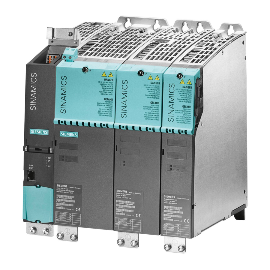
● A programming device (PG/PC) ● Startdrive commissioning tool ● A communication interface, e.g. PROFINET, Ethernet ● Completely wired-up drive line-up (see SINAMICS S120 manuals) A configuration example with booksize components and PROFINET communication is shown in the following figure:…
-
Page 62: Safety Instructions For Commissioning
• Observe the safety instructions provided in the hardware documentation. • When assessing the risk, take into account residual risks. Note Please observe the installation guidelines and safety instructions in the SINAMICS S120 Manuals. Commissioning with Startdrive Commissioning Manual, 11/2017, 6SL3097-4AA10-0BP1…
-
Page 63: Bico Interconnections
Further information Detailed information on BICO technology and BICO connections can be found in Section «Basics of the drive system» in the SINAMICS S120 Drive Functions Function Manual. In Startdrive for S120, the parameterization is possible via: ● Parameter view ●…
-
Page 64
Fundamentals 3.3 BICO interconnections Binectors, BI: Binector input, BO: Binector output A binector is a unitless digital (binary) signal that can assume a value of 0 or 1. Binectors are subdivided into binector inputs (signal sink) and binector outputs (signal source). -
Page 65: Interconnect Bico Inputs
Fundamentals 3.3 BICO interconnections 3.3.2 Interconnect BICO inputs Use a connection dialog to connect binector or connector inputs. Connecting a signal To make a connection, proceed as follows: 1. Click the binector or connector icon of the signal that you want to connect ( A connection dialog for the selection of the possible parameters opens.
-
Page 66
Fundamentals 3.3 BICO interconnections The last set signal source is displayed in the «Selected source» field. If a connection was not available previously, the value 0 is displayed. 2. Select the parameter that you want to connect. If connectable bits of the parameter are available, they are displayed in a drop-down list. Figure 3-3 BICO dialog input: Parameter bits opened 3. -
Page 67: Interconnecting Bico Outputs
Fundamentals 3.3 BICO interconnections 3.3.3 Interconnecting BICO outputs Use the connection dialog to connect binector or connector outputs. Connecting a signal To make a connection, proceed as follows: 1. Click the binector or connector icon of the signal that you want to connect ( A connection dialog for the selection of the possible parameters opens.
-
Page 68
Fundamentals 3.3 BICO interconnections The last set signal sink is displayed in the «Selected sinks» field. If a connection was not available previously, the text «No sink selected» is displayed. 2. Activate the check boxes for the parameters that you want to connect. If connectable bits of the parameter are available, they are displayed in a drop-down list. -
Page 69
Fundamentals 3.3 BICO interconnections Multiple connections at outputs Several interconnections can be set simultaneously for a parameter, which for reasons of space however, cannot be displayed in the interconnections field. Clicking the icon next to the interconnection field opens a list, which shows all of the active parameter interconnections. -
Page 70: Comparing Parameter Settings
Fundamentals 3.4 Comparing parameter settings Comparing parameter settings The current parameter values of a drive object can be compared with another parameter set using the comparison function in the parameter view. The following comparisons are possible: ● Offline — Factory setting ●…
-
Page 71
Fundamentals 3.4 Comparing parameter settings Icons in the «Comparison» column Icon Meaning The comparison values are equal and error-free. Offline — Factory setting: The comparison values are different and error-free. Online — Offline: The comparison values are different and error-free. Online — Factory setting: The comparison values are different and error-free. -
Page 72: Permanently Save The Settings
Fundamentals 3.5 Permanently save the settings Permanently save the settings Saving configurations in the project In Startdrive, settings are predominantly made via screen forms. The complete project must be saved in order that the settings made are permanently active. 1. Click «Save project» in the toolbar. — Or — 2.
-
Page 73: Restoring Factory Settings
Fundamentals 3.6 Restoring factory settings Restoring factory settings In online operation, you can restore the factory settings for the drive control. 1. Establish an online connection (Page 137) to your drive unit. 2. Click the icon in the function view of the active Startdrive project. The factory settings are restored.
-
Page 74: Loading Project Data From A Drive Unit
Fundamentals 3.7 Loading project data from a drive unit Loading project data from a drive unit Requirement ● A project is open. ● The hardware configuration and software to be loaded must be compatible with the Startdrive. If the data on the device was created with a previous program version or with a different configuration software, please make sure they are compatible.
-
Page 75
Fundamentals 3.7 Loading project data from a drive unit 3. Check the alarms in the «Upload preview» dialog, and select the necessary actions in the «Action» column. As soon as uploading becomes possible, the «Upload from device» button is enabled. 4. -
Page 76
Fundamentals 3.7 Loading project data from a drive unit Commissioning with Startdrive Commissioning Manual, 11/2017, 6SL3097-4AA10-0BP1… -
Page 77: Commissioning
Commissioning Call Startdrive Note The following procedure is based on the Windows 7 operating system. Operation can deviate slightly for other operating systems Call the Startdrive application 1. Click on the Startdrive icon of your user interface. — or — 2.
-
Page 78: Commissioning Workflow
Commissioning 4.2 Commissioning workflow Commissioning workflow A drive can be commissioned in two ways: ● Create a project offline in Startdrive The components of the drive are combined offline in Startdrive. ● Create a project by reading out a device configuration The components of the drive are read-out online and supplemented offline when required.
-
Page 79: Check Lists To Commission Sinamics S
Commissioning 4.3 Check lists to commission SINAMICS S Check lists to commission SINAMICS S Checklist for commissioning booksize power units The following checklist must be carefully observed. Read the safety instructions in the manuals before starting any work. Table 4- 1 Checklist for commissioning (booksize) Check Are the environmental conditions in the permissible range?
-
Page 80
Commissioning 4.3 Check lists to commission SINAMICS S Checklist for commissioning chassis power units The following checklist must be carefully observed. Read the safety instructions in the manuals before starting any work. Table 4- 2 Checklist for commissioning (chassis) Activity Are the environmental conditions in the permissible range? Are the components correctly installed in the cabinets? Is the specified air flow for cooling the devices ensured? -
Page 81
Commissioning 4.3 Check lists to commission SINAMICS S Activity Have the digital and analog signals been routed with separate cables? Has the distance from power cables been observed? Has the cabinet been properly grounded at the points provided? Has the connection voltage for the fans in the chassis components been adapted accordingly to the supply voltages? For operation on non-grounded supply systems: Has the connection bracket for the interference suppression at the Infeed Module or the Power Module been removed? -
Page 82: Creating A Project Offline In Startdrive
Commissioning 4.4 Creating a project offline in Startdrive Creating a project offline in Startdrive 4.4.1 Creating a new project or loading a project For projects, the choice is yours: ● You create a completely new project (see «Create new project»). ●…
-
Page 83
Commissioning 4.4 Creating a project offline in Startdrive 2. Enter the project data here: – Project name: Startdrive automatically counts each new project. – Path: The simpler the archive path for the project, the faster the project can be loaded. –… -
Page 84
Commissioning 4.4 Creating a project offline in Startdrive Opening an existing project If you wish to change the data of an existing project, then you can load this project at any time. 1. Click «Open existing project» in the secondary navigation in the portal view of Startdrive. A selection of the projects last used is displayed to the right in the detailed view. -
Page 85
Commissioning 4.4 Creating a project offline in Startdrive Click «Browse», double-click the required project in your directory structure, select project file «*.ap15». Figure 4-4 Opening an existing project from the directory Note In Startdrive, it is possible to determine the Startdrive version which last processed a project by its respective extension. -
Page 86: Recommended Order Of Creation
Commissioning 4.4 Creating a project offline in Startdrive This information is generated and administered in the user administration of the TIA Portal. Detailed information on project protection can be found in the Startdrive online help under «Using user administration». 4.4.2 Recommended order of creation After a new project has been created, the required components must be inserted into the device configuration –…
-
Page 87: Inserting The Drive Unit
Commissioning 4.4 Creating a project offline in Startdrive 4.4.3 Inserting the drive unit Requirement You have created a project (Page 82) or have opened an existing project. Inserting a drive unit via the project view Proceed as follows to insert new drive units in the project view: 1.
-
Page 88
Commissioning 4.4 Creating a project offline in Startdrive Ensure that the version number indicated on the right in the dialog correlates with the version number of your memory card on the drive unit. If the version numbers do not match, it will not be possible to go online later. On creation, the current firmware version is always suggested. -
Page 89
Commissioning 4.4 Creating a project offline in Startdrive 4. Select the drive unit from the list, and if required enter a different device name in the input field at the top left (default: «Drive unit_x»). Ensure that the version number indicated on the right in the dialog correlates with the version number of your memory card on the drive unit. -
Page 90
Commissioning 4.4 Creating a project offline in Startdrive If the «Open device view» option is activated, then the drive unit is immediately created in the device view. Figure 4-7 Inserting a drive unit Inserting a device in the network view Alternatively, you can insert a drive unit in the network view. -
Page 91: Inserting An Infeed Unit
Commissioning 4.4 Creating a project offline in Startdrive 4.4.4 Inserting an infeed unit 4.4.4.1 Inserting a space holder for an infeed unit Requirement ● A project has been created. ● The Control Unit is inserted in the device configuration. Note Sequence Generally, the infeed is inserted in the configuration immediately after the drive in the device view.
-
Page 92
Commissioning 4.4 Creating a project offline in Startdrive Inserting an infeed You insert an infeed using the hardware catalog 1. Open «Line Modules» in the hardware catalog. Active Line Modules, Basic Line Modules and Smart Line Modules can be selected. 2. -
Page 93
Commissioning 4.4 Creating a project offline in Startdrive 3. Drag the unspecified infeed to the device view. Figure 4-9 Infeed inserted Result Generally, the DRIVE-CLiQ connection is automatically established. The unspecified infeed must now be specified in more detail. Commissioning with Startdrive Commissioning Manual, 11/2017, 6SL3097-4AA10-0BP1… -
Page 94: Specifying An Infeed Unit
Commissioning 4.4 Creating a project offline in Startdrive 4.4.4.2 Specifying an infeed unit Up until now, only an unspecified component envelope (space holder) exists. This component envelope must now be specified in more detail by using an article number so that the components in the device view correspond to what you have installed in your actual drive system.
-
Page 95
Commissioning 4.4 Creating a project offline in Startdrive 3. In the secondary navigation of the inspector window, select «Line Module — Selection – ALM» A list of the Line Modules available is displayed to the right in «Line Module — Selection». Figure 4-11 Line Module — Selection 4. -
Page 96: Interconnecting Several Infeed Units In Parallel
Commissioning 4.4 Creating a project offline in Startdrive Data of the selected infeed unit is assigned to the unspecified infeed unit. The white area turns dark gray. As default setting, a DRIVE-CLiQ connection is established between interfaces X100 and X200. Result The infeed unit is inserted and specified.
-
Page 97
Commissioning 4.4 Creating a project offline in Startdrive Connecting infeed units in parallel To connect infeed units (Line Modules) in parallel with already added modules, proceed as follows: 1. Open «Line Modules» in the hardware catalog. 2. If you have not yet inserted any infeed unit, drag the desired, non-specified infeed unit into the device view and specify this infeed unit (refer to Chapter «Specifying an infeed unit (Page 94)»). -
Page 98: Editing Components In The Device View
Commissioning 4.4 Creating a project offline in Startdrive 4.4.4.4 Editing components in the device view Editing components The various components are displayed graphically in the device view. The device view provides the following editing options: ● Moving the component ● Deleting the component The editing options are subsequently described using an infeed unit as example.
-
Page 99
Commissioning 4.4 Creating a project offline in Startdrive Deleting the component Delete the components that you no longer require. 1. Right-click in the gray border. A shortcut menu opens. Figure 4-15 Deleting a DRIVE-CLiQ component 2. To delete the DRIVE-CLiQ component, select «Delete» from the shortcut menu. The component is deleted from the editor. -
Page 100: Editing A Drive-Cliq Connection
Commissioning 4.4 Creating a project offline in Startdrive 4.4.4.5 Editing a DRIVE-CLiQ connection DRIVE-CLiQ connections Blue lines are used to visualize the DRIVE-CLiQ connections between the various components. The connections must be created in accordance with the real wiring in the offline project.
-
Page 101
Commissioning 4.4 Creating a project offline in Startdrive Drawing the DRIVE-CLiQ connection A DRIVE-CLiQ connection is drawn between two DRIVE-CLiQ ports. 1. Left-click the output port and keep the mouse button pressed. Figure 4-17 Drawing the DRIVE-CLiQ connection 2. Drag the blue line displayed to the target port. A connection is established between the two ports. -
Page 102: Inserting A Motor Module Or Power Module
Commissioning 4.4 Creating a project offline in Startdrive 4.4.5 Inserting a Motor Module or Power Module When you create a Power Module or Motor Module, the «SERVO» drive object type (high dynamic drives) is active by default. However, if you are using the «VECTOR» drive object type (universal drives) in your hardware device configuration, you can change the type of the module in Startdrive.
-
Page 103: Inserting And Specifying A Motor Module
Commissioning 4.4 Creating a project offline in Startdrive 4.4.5.1 Inserting and specifying a Motor Module Using the hardware catalog, you insert a Motor Module in an unspecified form. 1. Open «Motor Modules» in the hardware catalog. A selection can be made from the following Motor Modules: –…
-
Page 104
Commissioning 4.4 Creating a project offline in Startdrive 3. Drag the unspecified Motor Module into the device view. Figure 4-19 Motor Module inserted The DRIVE-CLiQ connection is automatically established. 4. Click the Motor Module in the device view. Ensure that you click in the white area of the Motor Module. -
Page 105
Commissioning 4.4 Creating a project offline in Startdrive 6. In the secondary navigation of the inspector window, select «Motor Module — Selection — xxx». Figure 4-20 Motor Module specified All Motor Modules for the «SERVO» drive object type (default setting for first call) are displayed in the list. -
Page 106: Inserting And Specifying A Power Module
Commissioning 4.4 Creating a project offline in Startdrive 4.4.5.2 Inserting and specifying a Power Module You can add a Power Module in unspecified form via the hardware catalog. 1. Open the «Power Modules» item in the hardware catalog. The following Power Modules are available for selection: –…
-
Page 107
Commissioning 4.4 Creating a project offline in Startdrive 4. In the device view, click the Power Module. Make sure that you click on the white area of the Power Module. 5. Open the Inspector window if it has still not been opened or displayed. 6. -
Page 108: Making Detailed Settings
Commissioning 4.4 Creating a project offline in Startdrive 4.4.5.3 Making detailed settings Further detail settings can be carried out in the inspector window for Motor Modules and Power Modules: ● Motor Module settings/Power Module settings Allows the modification of the preallocated supply voltage. Indicates the standard for power settings of converter and motor.
-
Page 109: Connecting Several Modules In Parallel
Commissioning 4.4 Creating a project offline in Startdrive 4. If a drive object type is set for the «VECTOR» module, it is possible to set further additional data. Select the menu «Power Module Details > Power Module Additional Data» in the inspector window.
-
Page 110
Commissioning 4.4 Creating a project offline in Startdrive Connecting Motor Modules or Power Modules in parallel Parallel connection using a Motor Module as an example is explained below. 1. Open «Motor Modules» in the hardware catalog. 2. If you have not yet inserted any Motor Module in the device configuration, drag the desired, non-specified Motor Module into the device view and specify it (see Chapter «Inserting and specifying a Motor Module (Page 103)»). -
Page 111: Changing The Drive Object Type
Commissioning 4.4 Creating a project offline in Startdrive 4.4.5.5 Changing the drive object type The drive object type can be changed in the Motor Modules drop-down list or in the Power Modules drop-down list as well as in the project information of the drive axis. Requirement A Power Module or a Motor Module is created and, if required, specified in Startdrive in the device configuration.
-
Page 112
Commissioning 4.4 Creating a project offline in Startdrive Setting the drive object type in the project information 1. If the device configuration is not active in your Startdrive project, call it via the project tree. 2. Select the desired drive axis in the device configuration. 3. -
Page 113: Inserting A Motor
Commissioning 4.4 Creating a project offline in Startdrive 4.4.6 Inserting a motor Startdrive manages the motor data of numerous motors in a motor list. Motors can therefore be quickly specified via the Inspector window. If you want to manage the motors in your device configuration that are not contained in the motor list, you can acquire the most important motor data, such as the rating plate values of the motor, manually in the Inspector window.
-
Page 114: Inserting And Specifying Motors From The Motor List
Commissioning 4.4 Creating a project offline in Startdrive 4.4.6.1 Inserting and specifying motors from the motor list Inserting and specifying a motor You can insert motors in unspecified form using the hardware catalog. 1. Open «Motors» in the hardware catalog. The following motor types are available for selection: –…
-
Page 115
Commissioning 4.4 Creating a project offline in Startdrive 3. Drag the unspecified motor to the lower area of the Motor Module. Figure 4-30 Motor inserted 4. Click the unspecified motor in the device view. 5. Open the Inspector window if it has still not been opened or displayed. Commissioning with Startdrive Commissioning Manual, 11/2017, 6SL3097-4AA10-0BP1… -
Page 116
Commissioning 4.4 Creating a project offline in Startdrive 6. In the secondary navigation of the Inspector window, select «Motor — Selection — …». 7. Based on the article number, select a motor with the appropriate motor encoder from the list. Figure 4-31 Motor specified The data of the selected motor are assigned to the unspecified motor. -
Page 117: Inserting And Specifying Motors That Are Missing From The Motor List
Commissioning 4.4 Creating a project offline in Startdrive 4.4.6.2 Inserting and specifying motors that are missing from the motor list The mandatory fields for entering motor data manually are pink. Inserting and specifying a motor via motor data entry You can insert motors in unspecified form using the hardware catalog. 1.
-
Page 118
Commissioning 4.4 Creating a project offline in Startdrive 3. Drag the unspecified motor to the lower area of the Motor Module. Figure 4-33 Motor inserted 4. Click the unspecified motor in the device view. 5. Open the Inspector window if it has still not been opened or displayed. 6. -
Page 119
Commissioning 4.4 Creating a project offline in Startdrive 7. If you also want to acquire the optional motor data and circuit diagram data, activate the «Activate the display of the …» options in the «Rating plate values» screen form. The additionally activated subareas are displayed in the secondary navigation under «Motor details». -
Page 120: Inserting Measuring Systems
This is the reason that high quality encoders must be used for motor encoders. – Siemens motors that have already been configured are created in the device view with the matching encoder and the encoder evaluation.
-
Page 121
Commissioning 4.4 Creating a project offline in Startdrive Available measuring systems (encoder) The following encoder types are supported in Startdrive: ● DRIVE-CLiQ encoder These encoders are parameterized when downloading — and after an upload, are correctly displayed. ● SIN/COS encoders Incremental encoders that supply a sinusoidal/cosinusoidal type signal are also available with SSI protocol. -
Page 122
Commissioning 4.4 Creating a project offline in Startdrive Requirement ● A project has been created. ● The Control Unit is inserted in the device configuration. ● An infeed is inserted. In case of doubt, you can also add the infeed at a later point in time. However, in this case, you must manually wire the «infeed»… -
Page 123
Commissioning 4.4 Creating a project offline in Startdrive 2. Select the unspecified encoder in the device overview. Figure 4-35 Encoder selected Commissioning with Startdrive Commissioning Manual, 11/2017, 6SL3097-4AA10-0BP1… -
Page 124
Commissioning 4.4 Creating a project offline in Startdrive 3. Drag the unspecified encoder to the lower area of the Motor Module. Figure 4-36 Encoder inserted An encoder and a Sensor Module are created. 4. Click the unspecified encoder in the device view. 5. -
Page 125
Commissioning 4.4 Creating a project offline in Startdrive 6. In the secondary navigation of the Inspector window, select «Measuring system — Selection — …». Figure 4-37 Encoder specified 7. Select the required encoder in the «Measuring system — Selection — …» list. The data of the selected encoder are assigned to the unspecified encoder. -
Page 126: Specifying The Encoder Evaluation
Commissioning 4.4 Creating a project offline in Startdrive 4.4.7.2 Specifying the encoder evaluation Requirement You have already specified an encoder. The non-specific encoder evaluation is displayed. Specifying the encoder evaluation Various Sensor Modules are available for the encoder evaluation. Different types are offered for selection depending on the encoder.
-
Page 127
Commissioning 4.4 Creating a project offline in Startdrive The Sensor Modules that are available are listed in the inspector window. Figure 4-39 Encoder evaluation specified 2. Select your Sensor Module. Result The Sensor Module has been specified. Commissioning with Startdrive Commissioning Manual, 11/2017, 6SL3097-4AA10-0BP1… -
Page 128: Encoder System Connection
Commissioning 4.4 Creating a project offline in Startdrive 4.4.7.3 Encoder system connection Description The Sensor Modules evaluate the signals from the connected motor encoders or external encoders and convert the signals so that they can be evaluated by the Control Unit. The encoder system can only be connected to SINAMICS via DRIVE-CLiQ.
-
Page 129: Inserting Additional System Components
Commissioning 4.4 Creating a project offline in Startdrive 4.4.8 Inserting additional system components Various system components can be inserted (additionally) in the device configuration of your drive: ● CBE20 Communication Board ● Terminal Module ● Terminal Board ● VSM10 Voltage Sensing Module Since the handling of these system components differs when inserting, the insertion procedure is described separately in the following for each system component.
-
Page 130: Adding A Terminal Module
Commissioning 4.4 Creating a project offline in Startdrive Inserting the CBE20 in the Control Unit The CBE20 is a versatile Communication Board that can be used in Startdrive with the «SINAMICS-Link» communication profile. 1. Open «Supplementary system components > Communication Boards» in the hardware catalog.
-
Page 131
Commissioning 4.4 Creating a project offline in Startdrive Adding Terminal Modules With Terminal Modules, you can expand the interfaces of the Control Unit. They are connected to the Control Unit via DRIVE-CLiQ. Terminal Modules do not have to be specified any further. 1. -
Page 132: Adding A Terminal Board
Commissioning 4.4 Creating a project offline in Startdrive 4.4.8.3 Adding a Terminal Board Requirement ● A project has been created. ● A Control Unit is contained in the device configuration. ● No Communication Board CBE20 is contained in the device configuration. TB30 and CBE20 cannot be created simultaneously in the device configuration.
-
Page 133
Commissioning 4.4 Creating a project offline in Startdrive Adding a Terminal Board Terminal Board TB30 is a terminal module with which it is possible to expand the interfaces of the Control Unit. The Terminal Board is inserted into the option slot of the Control Unit. The Terminal Board does not have to be specified any further. -
Page 134: Adding The Vsm10 Voltage Sensing Module
Commissioning 4.4 Creating a project offline in Startdrive 4.4.8.4 Adding the VSM10 Voltage Sensing Module Voltage Sensing Modules (VSM) can be used for 2 different drive objects: ● Infeed unit Is used for voltage measurement, e.g. for the «mains transformer» function. A VSM10 allows an exact recording of the line voltage curve and supports the fault-free operation of the Line Modules in unfavorable network conditions.
-
Page 135
Commissioning 4.4 Creating a project offline in Startdrive Result The VSM10 is inserted in the selected drive object. The required DRIVE-CLiQ connections are drawn automatically. Figure 4-43 Example: Voltage Sensing Module VSM10 inserted in infeed unit The VSM10 does not have to be specified any further. Commissioning with Startdrive Commissioning Manual, 11/2017, 6SL3097-4AA10-0BP1… -
Page 136
Commissioning 4.4 Creating a project offline in Startdrive Operation of several VSMs per Line Module You can add a total of up to three VSMs to each Line Module using drag and drop. Note Activating the «Line transformer» function module If you operate several VSMs on one Line Module, you must activate the «Line transformer»… -
Page 137: Establishing An Online Connection To The Drive Unit
Commissioning 4.5 Establishing an online connection to the drive unit Establishing an online connection to the drive unit 4.5.1 Overview For Control Units of type CU320-2 PN, there are 2 interfaces available with which the drive unit can be accessed online. Interfaces for the online connection First you connect your PC to the appropriate Control Unit interface.
-
Page 138
Commissioning 4.5 Establishing an online connection to the drive unit IP addresses in the project A CU320-2 PN is created with the following IP addresses in a project in TIA Portal: ● Ethernet commissioning interface X127: The addresses correspond to the addresses that have already been assigned in the drive unit. -
Page 139: Connection Via Standard Ethernet Interface
Commissioning 4.5 Establishing an online connection to the drive unit Selecting the preferred PG/PC interface If you prefer to use a specific network interface of your PG/PC to establish an online connection, you can preset this interface. 1. Select the «Options > Settings» menu. The settings of the TIA Portal are displayed.
-
Page 140
Commissioning 4.5 Establishing an online connection to the drive unit Going online 1. Select the drive unit with which you want to go online in the project navigation (or in the device view). 2. Click the button. The «Go online» dialog opens. Figure 4-46 Go online 3. -
Page 141: Online Connection Via Profinet Interface
Commissioning 4.5 Establishing an online connection to the drive unit 7. In order to search for the drive unit with the set parameters, click «Start search». The devices that are found are displayed in the table of results. 8. Select your drive unit from the table. 9.
-
Page 142: Online Access Via Profinet
Commissioning 4.5 Establishing an online connection to the drive unit 4.5.3.2 Online access via PROFINET Use online access Get the TIA Portal to search for the drive via the online access of your computer. Requirement ● You have inserted a CU320-2 PN Control Unit. ●…
-
Page 143: Assigning An Ip Address
Commissioning 4.5 Establishing an online connection to the drive unit 4. Select the drive, and if necessary assign an IP address and device name, see also the Chapters «Assigning an IP address (Page 143)» and «Assigning PROFINET device names (Page 145)». Figure 4-48 PROFINET with IP address The drive is displayed with the device name (in this case, drive_1) and the IP address.
-
Page 144
Commissioning 4.5 Establishing an online connection to the drive unit Procedure To assign an IP address, proceed as follows: 1. Double-click «Online & Diagnostics» under «Online access» in the project navigator. 2. Double-click the «Functions» entry in the secondary navigation of the working area. 3. -
Page 145: Assigning Profinet Device Names
Commissioning 4.5 Establishing an online connection to the drive unit 4.5.3.4 Assigning PROFINET device names Assigning a name In addition to the IP address, the drive must also be assigned a device name for operation in a PROFINET subnet. The name must comply with the DNS name syntax; for detailed information, review the TIA Portal online help.
-
Page 146: Comparing Ip Addresses
Commissioning 4.5 Establishing an online connection to the drive unit 4.5.3.5 Comparing IP addresses IP address and the subnet mask in the project After you have assigned an IP address to the drive, check the IP address and subnet mask set in the project.
-
Page 147: Setting The Pg/ Pc Interface
Commissioning 4.5 Establishing an online connection to the drive unit 4.5.3.6 Setting the PG/ PC interface The PROFINET communication between the drive and the PG/PC is performed via an Ethernet interface. For PROFINET communication, the IP address and the subnet mask of the PG/PC interface must lie within the number range of the PROFINET subnet.
-
Page 148
Commissioning 4.5 Establishing an online connection to the drive unit Adding an IP address in the subnet 1. Click in the toolbar on button The «Go online» dialog opens. Figure 4-53 Selecting a device for online connection 2. Select the device and click «Connect» to confirm. 3. -
Page 149
Commissioning 4.5 Establishing an online connection to the drive unit 4. Click «Yes» to assign the IP address. Figure 4-55 IP address added 5. Confirm with «Yes». The interface has been assigned the IP address within the PROFINET subnet. Result ●… -
Page 150: Restoring Factory Settings
Commissioning 4.5 Establishing an online connection to the drive unit Displaying and deleting temporary IP addresses You can display and also delete all temporarily assigned addresses. 1. Navigate in the project navigation at «Online access» to the appropriate interface. 2. In the shortcut menu, click «Properties». 3.
-
Page 151
Commissioning 4.5 Establishing an online connection to the drive unit Procedure To restore the factory settings, proceed as follows: 1. Open the «Online & diagnostics» entry at «Online access». 2. Open the entry «Functions» in the secondary navigation. 3. Double-click the «Restore factory settings» entry in the secondary navigation. The dialog box with the current settings is displayed. -
Page 152: Alternatively: Creating A Project With A Device Configuration Derived From The Hardware
Commissioning 4.6 Alternatively: Creating a project with a device configuration derived from the hardware Alternatively: Creating a project with a device configuration derived from the hardware 4.6.1 Creating a new project For projects, the choice is yours: ● You create a completely new project (see «Create new project»). ●…
-
Page 153
Commissioning 4.6 Alternatively: Creating a project with a device configuration derived from the hardware 2. Enter the project data here: – Project name: Startdrive automatically counts each new project. – Path: The simpler the archive path for the project, the faster the project can be loaded. –… -
Page 154: Inserting The Drive Unit
Commissioning 4.6 Alternatively: Creating a project with a device configuration derived from the hardware 4.6.2 Inserting the drive unit Requirement You have created a project (Page 152) or have opened an existing project. Inserting a drive unit via the project view Proceed as follows to insert new drive units in the project view: 1.
-
Page 155: Deriving The Hardware Device Configuration
Commissioning 4.6 Alternatively: Creating a project with a device configuration derived from the hardware Ensure that the version number indicated on the right in the dialog correlates with the version number of your memory card on the drive unit. If the version numbers do not match, it will not be possible to go online later.
-
Page 156
Commissioning 4.6 Alternatively: Creating a project with a device configuration derived from the hardware Result The topology of the drive unit is read out. Existing DRIVE-CLiQ interconnections are transferred directly from the actual topology of the drive unit. The «Device configuration detection» dialog opens. Figure 4-61 Example: Device configuration detection — all components assigned All components found in the actual topology of the drive unit are displayed in an overview… -
Page 157
Commissioning 4.6 Alternatively: Creating a project with a device configuration derived from the hardware Selecting the drive object type of the motor controls After the device configuration has been read out, the drive object type in the header of the dialog box is automatically set to «High dynamic (servo)». -
Page 158
Commissioning 4.6 Alternatively: Creating a project with a device configuration derived from the hardware Deleting a component 1. Select the components which are to be deleted. 2. Call the «Delete» shortcut menu. The component is deleted. Note All components in the «Non-assignable components» folder prevent the creation of this read- out actual topology of the drive unit in the device configuration. -
Page 159: Transferring The Determined Device Configuration To Startdrive
Commissioning 4.6 Alternatively: Creating a project with a device configuration derived from the hardware 4.6.4 Transferring the determined device configuration to Startdrive Note Overwriting existing data in the device configuration If components already exist in the device configuration of the drive unit from which you started discovery of the device configuration, they will be deleted or overwritten when data are created by the automatic configuration.
-
Page 160
Commissioning 4.6 Alternatively: Creating a project with a device configuration derived from the hardware Result The topology is created in the device configuration of the selected drive unit. The original status of the online connection is re-established, as it was upon implementation of «Detection of the device configuration». -
Page 161: Revising The Configuration
Commissioning 4.6 Alternatively: Creating a project with a device configuration derived from the hardware 4.6.5 Revising the configuration Optimally, all components are transferred specified to the device configuration during an automatic configuration and do not have to be subsequently specified or supplemented. If this is the case, a message is shown in the message display that the automatic device configuration has been performed without error.
-
Page 162: Basic Parameterization Of The Drive Objects
Commissioning 4.7 Basic parameterization of the drive objects Basic parameterization of the drive objects 4.7.1 Control Unit 4.7.1.1 Web server Activating and configuring the web server The web server provides information on a SINAMICS device via its web pages. Access is via an Internet browser.
-
Page 163
Commissioning 4.7 Basic parameterization of the drive objects Calling up the web server configuration 1. In the project navigation, select menu «Drive control > Parameter». The corresponding detailed view is displayed at the right. 2. In the secondary navigation, call menu «Basic parameterization > Web server». The detailed view is updated. -
Page 164
Commissioning 4.7 Basic parameterization of the drive objects Restricting web server access to just secure connections Using the default configuration of the web server, you can access the SINAMICS frequency converter via an HTTP connection or via the encrypted HTTPS connection. Using the configuration, access can be restricted so that only a secure HTTPS connection is possible. -
Page 165
4.7 Basic parameterization of the drive objects Setting or changing web server user accounts For SINAMICS S120, the rights of both user accounts «SINAMICS» and «Administrator» are permanently defined and cannot be changed by users. The user «Administrator» has full rights by default. However, the standard «SINAMICS» user only has restricted access rights. -
Page 166
Commissioning 4.7 Basic parameterization of the drive objects Defining a password for a user You can create a password for both users «SINAMICS» and «Administrator» as follows: 1. Click on «Specify password». The «Specify password» dialog opens. Figure 4-66 Specifying the password 2. -
Page 167
Commissioning 4.7 Basic parameterization of the drive objects Deleting the password for user «SINAMICS» You can delete the password of user «SINAMICS» as follows: 1. Click the «Delete password» button. The «Delete password» dialog opens. Figure 4-67 Deleting the password 2. -
Page 168: Configuring Inputs/Outputs Of The Control Unit
Commissioning 4.7 Basic parameterization of the drive objects 4. Repeat the password in the «Confirm password» field. For security reasons, the password entries displayed in the input fields are encrypted. The entry is checked. If the entry is correct, the message «Password has been changed» is displayed.
-
Page 169
Commissioning 4.7 Basic parameterization of the drive objects Changing the view of the screen form The view of this screen form can be reduced to the essentials via a checkbox. Changing the function of one of the bidirectional digital inputs/outputs is not possible in the optimized view. The view of the screen form can also be switched to a simulation mode. -
Page 170
Commissioning 4.7 Basic parameterization of the drive objects Measuring sockets The measuring sockets output the analog signals. Any freely interconnectable signal can be output at any measuring socket. A measuring socket can be used, for example, to output the actual speed value (r0063) to a measuring instrument connected to the measuring socket. Figure 4-69 Measuring socket Note… -
Page 171
Commissioning 4.7 Basic parameterization of the drive objects Limitation on/off (p0784) With the «Limitation» drop-down list, select whether the output value of the measuring socket is to be restricted to the limit values of the characteristic curve for the required measuring socket. -
Page 172
Commissioning 4.7 Basic parameterization of the drive objects Define characteristic curve The scaling specifies the processing of the measured signal. This requires the definition of a straight line with two points. 1. Click the «Scaling» button in the adjustment range of a measuring socket. The «Scaling CU320 measuring socket Tx»… -
Page 173
1. Enter the required offset value in the «Offset» field for the relevant measuring socket. Function diagrams (see SINAMICS S120/S150 List Manual) Diagnostics — measuring sockets (T0, T1, T2) • 8134 Overview of important parameters (see SINAMICS S120/S150 List Manual) Adjustable parameters CI: Measuring sockets signal source • p0771[0…2] Measuring sockets characteristic curve value x1 •… -
Page 174: Infeed Unit
Commissioning 4.7 Basic parameterization of the drive objects 4.7.2 Infeed unit 4.7.2.1 Overview Infeed units (Line Modules) Line Modules contain the central line infeed for the DC link. Various Line Modules can be selected to address the various application profiles: ●…
-
Page 175: Function Modules
Commissioning 4.7 Basic parameterization of the drive objects 4.7.2.2 Function modules For the infeed, you can activate function modules offline as required. The function modules that can be activated are listed in the «Function modules» screen form. Figure 4-71 Example: Function modules for an ALM Note Function modules which can be activated are dependent upon the configuration selected for the infeed unit.
-
Page 176
Commissioning 4.7 Basic parameterization of the drive objects The function modules that can be used are presorted in two areas: ● Frequently used function modules – Master/slave Redundant operation of several ALMs on one DC link. – External Braking Module Control of an external Braking Module in order to be able to collect braking energy in the event of a power failure. -
Page 177: Line Data / Operating Mode
Commissioning 4.7 Basic parameterization of the drive objects 4.7.2.3 Line data / operating mode You set the most important parameters for the operation of an infeed in the function view of the «Line data / operating mode» screen form. The corresponding parameters are displayed depending on the infeed type.
-
Page 178
Commissioning 4.7 Basic parameterization of the drive objects Setting the line data and operating mode The parameters in this screen form are assigned default values when creating the device. 1. Enter a value for the device supply voltage in the «Device supply voltage» field (p0210). 2. -
Page 179: Enable Logic
Commissioning 4.7 Basic parameterization of the drive objects 4.7.2.4 Enable logic You can connect several signal sources for the enables in the function view of the «Enable logic» mask. Figure 4-73 Enable logic Procedure 1. Interconnect the signal source via «p0840» for «OFF1 (low active)». 2.
-
Page 180: Line Contactor Control
Commissioning 4.7 Basic parameterization of the drive objects 4.7.2.5 Line contactor control This function allows an external line contactor to be controlled. The closing and opening of the line contactor can be monitored by evaluating the feedback contact of the line contactor. Figure 4-74 Infeed: Line contactor control The line contactor can be controlled with the following drive objects via r0863.1:…
-
Page 181: Drive Axes Servo Drives
Commissioning 4.7 Basic parameterization of the drive objects 4.7.3 Drive axes SERVO drives 4.7.3.1 Overview Basic parameterization of the drive axes You can carry out basic parameterization for the following data of the drive axis/axes: ● Function modules ● Control mode ●…
-
Page 182: Function Modules
Commissioning 4.7 Basic parameterization of the drive objects 4.7.3.2 Function modules For the drive axis used, you can activate function modules offline as required. The function modules that can be activated are listed in the «Function modules» screen form. Figure 4-75 Example: Function modules — for drive axes Note The display of the function modules that can be activated is dynamic and depends on the…
-
Page 183: Control Mode
Commissioning 4.7 Basic parameterization of the drive objects 4.7.3.3 Control mode Control types Speed control (with and without encoder) and torque control are available for SERVO drives. Figure 4-76 Control mode ● Speed control The speed control of a variable-speed drive has the task of following the speed according to a specified setpoint (reference variable) as precisely as possible and without overshoot.
-
Page 184: Important Parameters
Commissioning 4.7 Basic parameterization of the drive objects 4.7.3.4 Important parameters Description You define the basic properties of the drive control using the important parameters. Figure 4-77 Important parameters Parameters Designation Description p1121 Ramp-down time Ramp-down time which the drive requires to decelerate from maximum speed (p1082) to standstill.
-
Page 185: Sampling Times/Pulse Frequency
Commissioning 4.7 Basic parameterization of the drive objects 4.7.3.5 Sampling times/pulse frequency As of a pulse frequency of 800 Hz, it is recommended that you enter the sampling times and the pulse frequency for the drive. The setting is made using the following screen form: Figure 4-78 Sampling times/pulse frequency Commissioning with Startdrive…
-
Page 186
Commissioning 4.7 Basic parameterization of the drive objects Setting the defaults The sampling times are preset via parameter p0112. 1. Select one of the following defaults via the drop-down list (p0112): – [0] Expert – [1] xLow – [2] Low –… -
Page 187
Commissioning 4.7 Basic parameterization of the drive objects Entering the sampling times manually If you have set «Expert» in p0112, you can manually configure each of the following sampling times for the following control loops (p0115): ● p0115[0]: Sampling times for internal control loops, current controller ●… -
Page 188: Enable Logic
Commissioning 4.7 Basic parameterization of the drive objects 4.7.3.6 Enable logic If telegrams were connected during commissioning, these interconnections are displayed here and an additional specification is not required. If no telegrams were specified previously, then you must connect the required signal sources via the enable logic.
-
Page 189
Commissioning 4.7 Basic parameterization of the drive objects Connecting signal sources 1. Connect the signal source for the «Infeed operation» (p0864) command. 2. Connect the signal source for the «OFF1 (low active)» command (p0840). This command corresponds to control word 1 bit 1 (STW1.1) in the PROFIdrive profile. 3. -
Page 190: Drive Axes Vector Drives
Commissioning 4.7 Basic parameterization of the drive objects 4.7.4 Drive axes VECTOR drives 4.7.4.1 Overview Basic parameterization of the drive axes You can carry out basic parameterization for the following data of the drive axis/axes: ● Function modules ● Control mode ●…
-
Page 191: Function Modules
Commissioning 4.7 Basic parameterization of the drive objects 4.7.4.2 Function modules You can connect various function modules for the associated deployed drive axis or for the deployed infeed. The function modules that can be activated are listed in the «Function modules»…
-
Page 192: Control Mode
Commissioning 4.7 Basic parameterization of the drive objects 4.7.4.3 Control mode Control types The following control types are available for VECTOR drives: ● U/f control with linear characteristic ● U/f control with linear characteristic and FCC ● U/f control with parabolic characteristic ●…
-
Page 193: Important Parameters
Commissioning 4.7 Basic parameterization of the drive objects Selecting the control type 1. Select one of the control modes listed above (p1300). The screen form is structured according to the selected control mode. Terminology for the use of linear motors When linear motors are used, a linear motion is executed instead of a rotary motion.
-
Page 194: Drive Settings
Commissioning 4.7 Basic parameterization of the drive objects 4.7.4.5 Drive settings No entries are required on this page for motors with DRIVE-CLiQ interface or motors of the motor database. Figure 4-83 Drive settings Setting the automatic calculation of motor/control parameters 1.
-
Page 195
Commissioning 4.7 Basic parameterization of the drive objects Setting the calculation of the controller data 1. Select one of the following options for the calculation of the controller data in the «Calculation controller data» (p0340) drop-down list: – No calculation The motor data is not calculated. -
Page 196: Enable Logic
Commissioning 4.7 Basic parameterization of the drive objects 4.7.4.6 Enable logic If telegrams were connected during commissioning, these interconnections are displayed here and an additional specification is not required. If no telegrams were specified previously, then you must connect the required signal sources via the enable logic.
-
Page 197
Commissioning 4.7 Basic parameterization of the drive objects Interconnecting signal sources 1. Connect the signal source for the «Infeed operation» (p0864) command. 2. Connect the signal source for the «OFF1 (low active)» command (p0840). This command corresponds to control word 1 bit 1 (STW1.1) in the PROFIdrive profile. 3. -
Page 198: Important Optimization Steps
Commissioning 4.7 Basic parameterization of the drive objects 4.7.5 Important optimization steps 4.7.5.1 Performing automatic controller optimization Using the «Automatic controller optimization» function (Auto Servo Tuning = AST), controller data of the speed controller loop (K , current setpoint filter) can be optimized. Figure 4-85 Automatic controller optimization Commissioning with Startdrive…
-
Page 199
Commissioning 4.7 Basic parameterization of the drive objects The following settings can be made as input parameters for the optimization. ● Measured signals – Amplitude Enter the amplitude of the measuring signal excitation as a percentage of the rated torque. As a rule, the drive can be optimized well with the amplitude presetting. -
Page 200
Commissioning 4.7 Basic parameterization of the drive objects Requirements: ● Startdrive is in online mode. ● Operation has been enabled. ● The SERVO type is set for the drive axis. ● The speed controller is active. ● Operation with encoder has been set. ●… -
Page 201
Commissioning 4.7 Basic parameterization of the drive objects 3. Confirm your entries with «OK». The «Measured signals» dialog closes. You can then specify the optimization type. 4. Select the desired optimization type in the «Optimization objective» drop-down list. – Robust (default setting) –… -
Page 202
Commissioning 4.7 Basic parameterization of the drive objects After you have made the optimization settings, you can start the measurements. 1. Click «Start» at the top right in the «Auto Servo Tuning» screen form. The following 4 consecutive measurements are now started to automatically optimize the controller: –… -
Page 203
Commissioning 4.7 Basic parameterization of the drive objects Accepting, checking and saving optimized values in the drive 1. Click «Accept calculated values». The optimized values are taken into the drive and saved there in the RAM. In the table, the values from the «Calculated value» column are transferred to the «Active value»… -
Page 204: Stationary/Rotating Measurement
Commissioning 4.7 Basic parameterization of the drive objects 4.7.5.2 Stationary/rotating measurement Motor identification (MotID) provides a means of determining motor data, for example, of third-party motors. To improve control properties of the motor, the MotID should be performed. The main motor identification components are the stationary and rotating measurements.
-
Page 205
Commissioning 4.7 Basic parameterization of the drive objects Requirements ● Startdrive is in the online mode. Assume master control You require master control for the selected drive to perform the motor identification. Master control has to be activated before the optimization measurements are started. 1. -
Page 206
Commissioning 4.7 Basic parameterization of the drive objects After performing the basic parameterization and subsequent download, the «Stationary measurement» measurement type is active as the «Calculation of motor/control parameters» has already been performed. 1. Click the «1» icon in the «Infeed » area to switch on the infeed. 2. -
Page 207: Loading The Project To The Target Device
Commissioning 4.8 Loading the project to the target device Loading the project to the target device In order to set up your project, you need to load the project data you generated offline on the connected drive units. This project data is generated, for example when configuring hardware, networks, and connections or when programming the user program or when creating recipes.
-
Page 208
Commissioning 4.8 Loading the project to the target device 3. Check the messages in the «Load preview» dialog. Activate the required actions in the «Action» column to perform a secure download. Figure 4-88 Example: Load preview As soon as downloading becomes possible, the «Load» button is enabled. 4. -
Page 209: Commissioning A Drive
Commissioning 4.9 Commissioning a drive Commissioning a drive 4.9.1 Using the control panel Traverse the drive and test the settings that have already been made with the control panel (see also the overview in Section «Drive control panel (Page 44)»). WARNING Non-observance of the safety instructions for the drive control panel The safety shutdowns from the higher-level controller have no effect with this function.
-
Page 210
Commissioning 4.9 Commissioning a drive Calling the control panel 1. In the project tree, select the «Drive unit_x > Drive axis_x > Commissioning» menu. 2. In the commissioning secondary navigation, select the «Control panel» menu. When an online connection has been established, the bar in the header area is shown in color. -
Page 211
Commissioning 4.9 Commissioning a drive Activating the infeed If an infeed is available in your drive, then the infeed must also be activated. If it is not activated, no further drive release can be set. 1. Click the «1» icon at «Infeed» to switch on the infeed. Deactivating the control panel When you deactivate the control panel, you return the master control. -
Page 212: Traversing The Drive With Speed Specification
Commissioning 4.9 Commissioning a drive 4.9.2 Traversing the drive with speed specification After you have set the drive enables, in the «Control Panel» screen form specify the operating mode and switch on the motor. Specifying the setpoint To specify the setpoint, proceed as follows: 1.
-
Page 213: Basic Positioner
Commissioning 4.9 Commissioning a drive 4.9.3 Basic positioner 4.9.3.1 Manual positioning Performing manual positioning in the drive control panel With manual positioning, you traverse the drive endlessly or with jog position-controlled with a defined velocity and acceleration. Requirement ● Startdrive is in online mode. ●…
-
Page 214: Relative Positioning
Commissioning 4.9 Commissioning a drive 4.9.3.2 Relative positioning Using relative positioning Use the «Relative positioning» function to traverse an axis a defined distance with the aid of the control panel. Requirement ● Startdrive is in online mode. ● The «Basic positioner» function module is activated. ●…
-
Page 215: Absolute Positioning
Commissioning 4.9 Commissioning a drive 4.9.3.3 Absolute positioning Using absolute positioning With «Absolute positioning» you traverse the axis to an absolute position. The function is oriented towards «Direct setpoint specification / MDI». Requirement ● Startdrive is in online mode. ● The «Basic positioner» function module is activated. ●…
-
Page 216: Modify Traversing Block
Commissioning 4.9 Commissioning a drive 4.9.3.4 Modify traversing block Using «Modify traversing blocks» You traverse the programmed traversing blocks with «Modify traversing blocks». You can test individual traversing blocks or all programmed traversing blocks in an automatic run. Requirement ● Startdrive is in online mode. ●…
-
Page 217: Note Regarding The Control Panel
Commissioning 4.9 Commissioning a drive 4.9.4 Note regarding the control panel Additional commissioning functions Other commissioning functions are helpful for the drive axes: ● Automatic controller optimization (Page 198) ● Stationary/rotating measurement (Page 204) Commissioning with Startdrive Commissioning Manual, 11/2017, 6SL3097-4AA10-0BP1…
-
Page 218: Safety Integrated Commissioning
Commissioning 4.10 Safety Integrated commissioning 4.10 Safety Integrated commissioning 4.10.1 Overview The drives of the SINAMICS S120 family are equipped with the following drive-autonomous safety functions: Table 4- 4 Overview of the Safety Integrated Functions Functions Abbr. With Without Brief description…
-
Page 219
● For information on how to generate the license key for the products «SINAMICS Safety Integrated Extended Functions» and «SINAMICS Safety Integrated Advanced Functions», see Section «Licensing» in the SINAMICS S120 Drive Functions Function Manual, Chapter «Licensing». An insufficient license is indicated via the following alarm and LED: –… -
Page 220
● Performing the safety function selection (Page 223) More detailed information More detailed theoretical information on the Safety Integrated Functions can be found: ● In the SINAMICS S120 Safety Integrated Function Manual, Section «Overview of Safety Integrated Functions». ● In the Startdrive online help. -
Page 221
4.10 Safety Integrated commissioning WARNING Non-observance of safety instructions and residual risks If the safety instructions and residual risks described in the SINAMICS S120 Safety Integrated Function Manual are not observed, accidents can occur involving severe injuries or death. • Observe the safety instructions of the SINAMICS S120 Safety Integrated Function Manual. -
Page 222: Making Basic Settings
Commissioning 4.10 Safety Integrated commissioning 4.10.2 Making basic settings 4.10.2.1 Starting the safety commissioning Requirement For safety reasons, you can only set the safety-relevant parameters of the 1st channel offline for Startdrive. To set the safety-relevant parameters of the 2nd channel, the drive must be online.
-
Page 223: Making Basic Safety Settings
Commissioning 4.10 Safety Integrated commissioning 4.10.2.2 Making basic safety settings Selecting the safety functionality Note The selection of the safety functionality can be made offline. The selection can be made online with active safety commissioning (processing mode). 1. In the secondary navigation of the drive axis, execute the «Drive functions > Safety Integrated >…
-
Page 224
Commissioning 4.10 Safety Integrated commissioning Making the basic settings for the Safety Basic Functions The «Basic Functions» setting is selected in the first drop-down list. Figure 4-90 Basic functions 1. Select one of the following settings in the «Control type» drop-down list: –… -
Page 225
Commissioning 4.10 Safety Integrated commissioning Making the basic settings for the Safety Extended/Advanced Functions The «Extended/Advanced Functions» setting is selected in the first drop-down list. Figure 4-91 Extended functions 1. In the second drop-down list, select whether a safety-capable encoder is used: –… -
Page 226: Accepting The Settings In The Drive
Commissioning 4.10 Safety Integrated commissioning 4.10.2.3 Accepting the settings in the drive After you have parameterized all safety functions, the drive must accept the settings. Note To accept the settings in the drive, it must be online. 1. To accept the settings and deactivate the safety functions, click the icon in the toolbar.
-
Page 227: Changing The Safety Password
Commissioning 4.10 Safety Integrated commissioning 4.10.2.4 Changing the safety password Note The machine manufacturer decides whether or not a password is required. The probability of failure (PFH) and certification of the safety functions apply even if no password has been set. The safety password can only be read or changed in online mode.
-
Page 228: Basic Functions
Commissioning 4.10 Safety Integrated commissioning 4.10.3 Basic functions 4.10.3.1 STO/SS1/SBC (Basic Functions) The «Safe Torque Off» (STO) function prevents energy from being supplied to the motor which can generate a torque. The «Safe Stop 1» (SS1) function brakes the motor and triggers the STO function after a delay time.
-
Page 229
Commissioning 4.10 Safety Integrated commissioning 2. Click the button (Select STO) to configure the «STO» function. The «Control» screen form opens. The display of the screen form depends on the basic settings of the Safety Integrated Basic Functions. In this screen form, configure the controls via the fail-safe inputs and outputs and/or PROFIsafe (see Section «Control (Page 281)»). -
Page 230: Function Diagrams And Parameters
• 2811 SI basic functions — SBC (Safe Brake Control), SBA (Safe Brake Adapter) • 2814 Overview of important parameters (see SINAMICS S120/S150 List Manual) CO/BO: SI status (Control Unit + Motor Module) • r9773.0…31 CO/BO: SI status (group STO) •…
-
Page 231: Extended Functions
Commissioning 4.10 Safety Integrated commissioning 4.10.4 Extended functions 4.10.4.1 Restrictions The Safety Integrated extended functions SS1, SLS, SDI and SSM without encoder do not require safe speed actual value acquisition. If an encoder is used for the drive control, this has no influence on the sensorless safety functions.
-
Page 232
Commissioning 4.10 Safety Integrated commissioning Safe, encoderless actual value acquisition is based on the measurement of current and voltage variables, which can influence the following functions. This does not result in unsafe states. However, this fault can be expected to have a negative impact on availability. Note Irregular operating states Note that in irregular operating states (e.g. -
Page 233
Commissioning 4.10 Safety Integrated commissioning ● Data set switchover The motor and drive data switchover can always be used for safety functions without encoder. It is not possible to switch over between induction and synchronous motors (this is interlocked). For several motor data sets it must be ensured that all motors have the same number of pole pairs. -
Page 234: Sto/Sbc (Extended Functions)
Commissioning 4.10 Safety Integrated commissioning Stable operation with active extended functions without encoder The following requirements must be fulfilled to avoid error messages from the safe actual value acquisition without encoder: ● Make sure that the motor and the power unit are adequately dimensioned for this application.
-
Page 235
Commissioning 4.10 Safety Integrated commissioning 2. Click the button (Select STO) to configure activation of the «STO» function. The «Control» screen form opens. The display of the screen form depends on the basic settings of the Safety Integrated Extended Functions. In this screen form, configure the controls via the fail-safe inputs and outputs and/or PROFIsafe (see Section «Control (Page 281)»). -
Page 236: Ss1 (Extended Functions)
Commissioning 4.10 Safety Integrated commissioning 4.10.4.3 SS1 (extended functions) Make the settings for the motor deceleration in the «Safe Stop 1» (SS1) screen form. The «SS1» function brakes the motor, monitors the magnitude of the motor deceleration within specified limits, and after a delay time or violation of a speed threshold, triggers the «STO» function.
-
Page 237
Commissioning 4.10 Safety Integrated commissioning Settings Method of operation SS1 with SBR and OFF3 In this case, there is no SS1 delay time active. The transition from SS1 to • (without encoder) STO depends entirely on the speed falling below the shutdown speed (p9560). -
Page 238
Commissioning 4.10 Safety Integrated commissioning Configuring the motor deceleration with internal braking response (OFF 3) 1. Select the «[0] SS1 with OFF 3» setting from the «Braking response» drop-down list. The screen form is structured accordingly. 2. Select the monitoring type in the «Monitoring» drop-down list: –… -
Page 239: Sos (Extended Functions)
Commissioning 4.10 Safety Integrated commissioning 4.10.4.4 SOS (extended functions) The «Safe Operating Stop» (SOS) function is used for fail-safe monitoring of the standstill position of a drive. Positions of a user-defined standstill tolerance are interpreted by the drive as «standstill». Figure 4-100 Standstill monitoring WARNING Unplanned movement of the drive through mechanical forces…
-
Page 240
Commissioning 4.10 Safety Integrated commissioning Effectiveness of the SOS function: The SOS function comes into effect in the following cases: ● After SOS is selected and the delay time (in p9551) has expired The drive must be braked to standstill within this delay time, e.g. by the controller. ●… -
Page 241: Ss2 (Extended Functions)
Commissioning 4.10 Safety Integrated commissioning 4.10.4.5 SS2 (extended functions) The «Safe Stop 2» («SS2») function is used to brake the motor safely along the OFF3 deceleration ramp (p1135) with subsequent transition to the «SOS» state (see Chapter «Safe Operating Stop (SOS) (Page 239)») after the delay time expires (p9552). The delay time set must allow the drive to brake to a standstill from every speed of the operating process within this time.
-
Page 242
Commissioning 4.10 Safety Integrated commissioning Example: Configuring the motor deceleration with internal braking response (OFF 3) 1. Select the monitoring type in the «Monitoring» drop-down list: – with SAM – with SBR 2. Click «Monitoring» and parameterize the alternative brake monitoring functions «SAM» and «SBR»… -
Page 243: Sam/Sbr (Extended Functions)
Commissioning 4.10 Safety Integrated commissioning 1. Set the «SS2E enable» switch to «Connection». 2. Enter the required delay time in the «Delay time SS2E -> SOS active» (p9553) input field. 3. Enter the required delay time in the «Delay time Stop E -> SOS active» (p9554) input field. 4.
-
Page 244
Commissioning 4.10 Safety Integrated commissioning «SAM» recognizes if the drive accelerates beyond the velocity tolerance defined in p9548 during the ramp-down phase, and triggers a STOP A. The monitoring is performed as follows: ● The monitoring through «SAM» is activated for «SS1» (or STOP B) and «SS2» (or STOP C). -
Page 245
Commissioning 4.10 Safety Integrated commissioning Safe Brake Ramp (SBR) The «Safe Brake Ramp» (SBR) function provides a safe method for monitoring the brake ramp. The «Safe Brake Ramp» function is used to monitor braking with the functions «SS1 with/without encoder,» «SLS without encoder,» SS2 and STOP B / STOP C (for safety with encoder). -
Page 246: Sbt (Diagnostic Function)
● The parameters of the «SBT» function are protected by the safety password, and can only be changed in the safety commissioning mode. ● Using this function, brakes can be tested that are directly connected to the SINAMICS S120 (integrated brake control), but also externally controlled brakes (e.g. via a PLC). Commissioning with Startdrive…
-
Page 247
Commissioning 4.10 Safety Integrated commissioning ● Test configurations: A maximum of two brakes can be tested: – A motor holding brake, controlled by the integrated brake control of the SINAMICS, and in addition, an externally controlled brake. – Two externally controlled brakes –… -
Page 248
Commissioning 4.10 Safety Integrated commissioning Requirements The following requirements must be satisfied when using the «SBT» function: ● The Safety Integrated Extended Functions must be enabled; also available for the Safety Integrated Extended Functions without selection. ● Safe Brake Control must be enabled when testing a brake controlled by SINAMICS (motor holding brake). -
Page 249
Commissioning 4.10 Safety Integrated commissioning Configuring the brake test via BICO interconnection 1. Select the «SBT via BICO» setting in the «Select SBT» drop-down list. 2. Select the test settings in the «Brake 1» and «Brake 2» drop-down lists. See «Features / Test configurations». 3. -
Page 250
Commissioning 4.10 Safety Integrated commissioning Configuring the brake test via test stop selection 1. Select the «Test stop selection» setting in the «Select SBT» drop-down list. 2. Select the direction of the test torque for SBT in the «Test direction» drop-down list. 3. -
Page 251: Communication Via Sic/Scc
Commissioning 4.10 Safety Integrated commissioning 4.10.4.8 Communication via SIC/SCC The following shows the tests of two different brake types: Test of a motor holding brake The following figure shows the communication via SIC and SCC during the test of a motor holding brake: Commissioning with Startdrive Commissioning Manual, 11/2017, 6SL3097-4AA10-0BP1…
-
Page 252
Commissioning 4.10 Safety Integrated commissioning Test of an external brake The following figure shows the communication via SIC and SCC during the test of an external brake: Commissioning with Startdrive Commissioning Manual, 11/2017, 6SL3097-4AA10-0BP1… -
Page 253: Sls (Extended Functions)
Commissioning 4.10 Safety Integrated commissioning 4.10.4.9 SLS (Extended Functions) The «Safely-Limited Speed» («SLS») function is used to protect a drive against unintentionally high speeds in both directions of rotation. This is achieved by monitoring the current drive speed up to a speed limit. «SLS»…
-
Page 254
Commissioning 4.10 Safety Integrated commissioning Settings 1. Call the «SLS» safety functions. A screen form with this name opens. Figure 4-104 Example: SLS-PROFIsafe with onboard terminals 2. Click the button (Select SLS) to configure activation of the «SLS» function. The «Control» screen form opens. The way the screen form is displayed depends on the basic settings of the Safety Integrated function SLS. -
Page 255
Commissioning 4.10 Safety Integrated commissioning Result The speed limit value of the drive is configured. The present SLS limit value is displayed in the field of that name (r9714[2]). The effective setpoint limit is displayed in the field of that name (r9733). -
Page 256
Commissioning 4.10 Safety Integrated commissioning 6. Click the icon to open the configuration for the speed limit. The dialog box «Stop response C/D/E» opens. The settings are identical to screen form «SS2». Set the desired motor deceleration here (see Chapter «SS2 (extended functions) (Page 241)») 7. -
Page 257: Ssm (Extended Functions)
Commissioning 4.10 Safety Integrated commissioning 4.10.4.10 SSM (extended functions) The «Safe Speed Monitor» («SSM») function is used for safely identifying when a velocity limit is undershot (p9546) in both directions of rotation, e.g. to detect standstill. A fail-safe output signal is available for further processing. SSM with hysteresis A velocity hysteresis can be configured for the «SSM»…
-
Page 258
Commissioning 4.10 Safety Integrated commissioning Example: Settings: 1. Select the «Enable» setting in the «SSM with hysteresis» drop-down list in the «SSM» screen form. The «Velocity hysteresis» input field is displayed together with the «Filter time» field. 2. Enter the required value in mm/min in the «Velocity hysteresis» (p9547) field. 3. -
Page 259
Commissioning 4.10 Safety Integrated commissioning Differences between Safe Speed Monitor with and without encoder ● For Safe Speed Monitor without encoder, after pulse suppression the drive is unable to determine the current velocity. Two responses can be selected for this operating state with the «SSM active feedback for pulse inhibit»… -
Page 260: Sdi (Extended Functions)
Commissioning 4.10 Safety Integrated commissioning The speed remains below the velocity limit p9546 throughout the entire monitoring period. Therefore, the SSM feedback signal remains r9722.15 = 1. After the command for pulse suppression, the motor speed drops. The internal STO is set when the speed drops below the standstill detection level.
-
Page 261
Commissioning 4.10 Safety Integrated commissioning Example: 1. Enter a delay time in ms in the «Delay time for selection of SDI -> SDI active» (p9565) field. 2. Enter a monitoring tolerance in mm in the «Monitoring tolerance» (p9564) field. 3. Select the required stop response in the «Selection» (p9566) drop-down list. 4. -
Page 262
Commissioning 4.10 Safety Integrated commissioning Differences for SDI «without selection» As an alternative to control via «onboard terminals» and/or «PROFIsafe», there is also the option of parameterizing SDI «without selection». In this case, SDI will be permanently active after POWER ON (with encoder) or will be active after switch-on (without encoder). 1. -
Page 263: Sla (Extended Functions)
Commissioning 4.10 Safety Integrated commissioning 4.10.4.12 SLA (Extended Functions) The safety function «Safely-Limited Acceleration» (SLA) monitors the motor for violation of the defined speed limit (e.g. in setup mode). SLA detects early on whether the drive is accelerating too quickly and initiates the stop response. SLA has no effect with braking. Figure 4-109 SLA overview Precondition ●…
-
Page 264
Commissioning 4.10 Safety Integrated commissioning Setting Safely-Limited Acceleration Figure 4-110 Example: SLA 1. In field «Acceleration limit» (p9578), enter a value for the acceleration limit for Safely- Limited Acceleration. This limit value applies to a positive and negative direction of rotation. The possible acceleration resolution is shown by the drive in r9790. -
Page 265: Function Diagrams And Parameters
(Page 251)»). You will find this status word in telegrams 700 and 701. 4.10.4.13 Function diagrams and parameters Function diagrams (see SINAMICS S120/S150 List Manual) SI Basic Functions — SBC (Safe Brake Control), SBA (Safe Brake Adapter) • 2814 SI Extended Functions — SS1, SS2, SOS, internal STOP B, C, D, F •…
-
Page 266
Commissioning 4.10 Safety Integrated commissioning Overview of important parameters (see SINAMICS S120/S150 List Manual) CO/BO: SI Status (Control Unit + Motor Module) • r9773.0…31 CO/BO: SI Status (group STO) • r9774.0…31 SI monitoring cycle (Control Unit) • r9780 OFF3 ramp-down time •… -
Page 267
Commissioning 4.10 Safety Integrated commissioning SI Motion STO delay bus failure (Control Unit) • p9580 SI Motion braking ramp reference value (Control Unit) • p9581 SI Motion braking ramp delay time (Control Unit) • p9582 SI Motion braking ramp monitoring time (Control Unit) •… -
Page 268
Commissioning 4.10 Safety Integrated commissioning SI Motion SLA stop response (Control Unit) • p9579 CO: SI motion diagnostics velocity: Actual SLA velocity limit on the • r9714[3] Control Unit CO/BO: SI Motion control signals 2: Deselect SLA • r9719.17 CO/BO: SI Motion drive-integrated control signals: Deselect SLA •… -
Page 269: Advanced Functions
Commissioning 4.10 Safety Integrated commissioning 4.10.5 Advanced Functions 4.10.5.1 Safe homing (Advanced Functions) The «Safe referencing/homing» function allows a safe absolute position to be defined. This safe position is required for the following safety functions: ● Safely-Limited Position (SLP) ● Safe Position (SP) ●…
-
Page 270
Commissioning 4.10 Safety Integrated commissioning Homing types SINAMICS distinguishes between two types of homing: ● Initial homing For initial safe homing, or in the event of a fault during a subsequent homing, the following steps are necessary: – The home position determined by the controller is entered in parameter p9572 and is declared to be valid with p9573 = 89. -
Page 271: Slp (Advanced Functions)
Commissioning 4.10 Safety Integrated commissioning Current actual position value in parameter r9708 The diagnostics information in parameter r9708 is displayed with the following properties: Table 4- 5 Value range and resolution (32-bit) Linear axis Rotary axis Position values ±737280000 ±737280000 Unit 1 μm 0.001 °…
-
Page 272
Commissioning 4.10 Safety Integrated commissioning Control and status signals of SLP Selecting «SLP» and switching over between the position ranges is performed via an F-DI or a PROFIsafe control bit. The SLP selection can be checked via parameter r9720.6. The selected position range can be checked via parameter r9720.19. -
Page 273: Sp (Advanced Functions)
Commissioning 4.10 Safety Integrated commissioning 4.10.5.3 SP (Advanced Functions) The «Sichere Position» («SP») function enables you to transfer safe position values to the higher-level fail-safe controller (F-CPU) via PROFIsafe (telegrams 901, 902, or 903). From the position change over time, the F-CPU can also calculate the current velocity. In telegram 902, the values are transferred in 32-bit format, in telegram 901, in 16-bit format.
-
Page 274: Sca (Advanced Functions)
Commissioning 4.10 Safety Integrated commissioning Configuring safe absolute position 1. Select the «Absolute» setting in the «Safe Position» drop-down list. 2. Click «Safe homing» and check the actual position values in the dialog of the same name. 3. Enter a tolerance value for checking the actual values in the «Tolerance for actual value comparison»…
-
Page 275
Commissioning 4.10 Safety Integrated commissioning Note The smallest possible tolerance band should be selected for the SCA function (< 5 … 10 mm). It makes sense to parameterize the cam tolerance to be greater than or equal to the actual value tolerance. 2. -
Page 276: Function Diagrams And Parameters
SI Extended Functions — SCA (Safe Cam) • 2826 SI Extended Functions — S_ZSW_CAM1 Safety status word Safe Cam 1 • 2844 Overview of important parameters (see SINAMICS S120/S150 List Manual) Safe homing SI Motion home position (Control Unit) • p9572 SI Motion accept home position (Control Unit) •…
-
Page 277
Commissioning 4.10 Safety Integrated commissioning SI Motion SLP (SE) stop response (Control Unit) • p9562[0…1] SI Motion SLP retraction F-DI (CPU 1) • p10009 SI Motion SLP retraction F-DI (CPU 2) • p10109 SI Motion SLP input terminal (CPU 2) •… -
Page 278: Global Settings And Information
Commissioning 4.10 Safety Integrated commissioning 4.10.6 Global settings and information 4.10.6.1 Parameterizing the actual value acquisition / mechanical system The actual value acquisition / mechanical system can only be parameterized for the extended functions. For parameterization of the actual value acquisition, only the parameters required for your configuration are offered: Para- Required for the configuration:…
-
Page 279
Commissioning 4.10 Safety Integrated commissioning Para- Required for the configuration: meter — Encoder system — Motor type — Axis type ① ② ③ ④ ⑤ ⑥ ⑦ Pulse number p9518 – – This field shows the number of pulses of the encoder used. Fine resolution p9519 –… -
Page 280
Commissioning 4.10 Safety Integrated commissioning Para- Required for the configuration: meter — Encoder system — Motor type — Axis type ① ② ③ ④ ⑤ ⑥ ⑦ Leadscrew pitch p9520 – – – – – – Here, you set the transmission ratio between the encoder and load in mm (linear axis with rotary encoder) (only avail- able for linear axis). -
Page 281: Configuring The Control Of The Safety Functions
4.10.6.2 Configuring the control of the safety functions In the «Control» screen form, you can parameterize the settings of the SINAMICS S120 for the fail-safe inputs and outputs or the control via PROFIsafe. Only the parameters required for the selected control type (see Chapter «Making basic safety settings (Page 223)») are displayed in the screen form.
-
Page 282
Commissioning 4.10 Safety Integrated commissioning For internal faults or limit value violations, the drive-internal safety functions issues safety faults. 1. Interconnect signal source p9620 for the safety functions STO, SS1 or SBC to the Control Unit. Only the fixed zero and digital inputs DI 0 … 7, 16, 17, 20 and 21 are permissible as signal sources. -
Page 283: Forced Checking Procedure (Test Stop)
Commissioning 4.10 Safety Integrated commissioning Note Unique PROFIsafe addresses You must ensure the unique assignment of the PROFIsafe address throughout the network and the CPU. • The fail-safe I/O of PROFIsafe address type 1 is addressed clearly by its fail-safe destination address.
-
Page 284
Commissioning 4.10 Safety Integrated commissioning To parameterize the forced checking procedure (test stop) for the Basic Functions, proceed as follows: 1. Enter the interval for performing dynamization and testing the safety shutdown paths in the «Timer» (p9659) field. Within the parameterized time, the «STO» function must be selected and deselected at least once. -
Page 285
Commissioning 4.10 Safety Integrated commissioning To parameterize the forced checking procedure (test stop) for the extended functions, proceed as follows: 1. If the test stop is to be executed during ramp-up, establish a connection for «Execute test stop automatically during ramp-up». The line in the button must be continuous. — Or — If the test stop is not to be executed automatically during ramp-up, select the signal (p9705) that is to trigger the forced checking procedure. -
Page 286: Function Status Of The Safety Integrated Settings
Commissioning 4.10 Safety Integrated commissioning 4.10.6.4 Function status of the Safety Integrated settings The «Function Status» screen form displays a list of all Safety Integrated functions on the left. Figure 4-116 Example: Safety Integrated function status All Safety Integrated functions activated in Startdrive are identified by a green LED. In addition, the most important information of the selected Safety Integrated functions is displayed.
-
Page 287: Function Diagrams And Parameters
• 2810 SI PROFIsafe — Standard telegrams • 2915 SI PROFIsafe — Manufacturer-specific telegrams • 2917 Overview of important parameters (see SINAMICS S120/S150 List Manual) Control SI PROFIsafe address (Control Unit) • p9610 SI PROFIsafe failure response (Control Unit) • p9612 SI SGE changeover discrepancy time (Control Unit) •…
-
Page 288: Configuring Brake Control
Configuring brake control 4.11.1 Overview The drives of the SINAMICS S120 family are equipped with a brake control for motor holding brakes: The brake control is only used for the control of motor holding brakes. A differentiation is made between mechanically braking and electrically braking a motor: ●…
-
Page 289: Simple Brake Control
Commissioning 4.11 Configuring brake control 4.11.2 Simple brake control 4.11.2.1 Basics The «Simple brake control» is used exclusively for the control of holding brakes. Drives that have been switched off, can be secured against unwanted motion by the holding brake. The trigger command for releasing and applying the holding brake is transmitted via DRIVE- CLiQ from the Control Unit, which monitors and logically connects the signals to the system- internal processes, directly to the Motor Module.
-
Page 290: Parameterizing The Brake Control
Commissioning 4.11 Configuring brake control Commissioning Simple brake control is activated automatically (p1215 = 1) when the Motor Module has an internal brake control and a connected brake has been found. If no internal brake control is available, the control can be activated via parameter (p1215 = WARNING Danger as a result of a damaged holding brake caused by incorrect parameter assignment If the drive moves against the closed holding brake, this can destroy the holding brake and…
-
Page 291
Commissioning 4.11 Configuring brake control To select the type of brake control, proceed as follows: 1. Select the «Drive functions > Brake control» menu in the project navigator. 2. Select one of the following entries from the drop-down list: – Motor holding brake like sequence control (p1215 = 1) If the configuration is set to «No motor holding brake available»… -
Page 292
Commissioning 4.11 Configuring brake control Parameterizing the «Motor holding brake like sequence control» option To parameterize the «Motor holding brake like sequence control» option, proceed as follows: 1. Set the opening time of the brake (p1216). After activating the holding brake (opening), the speed/velocity setpoint zero is active during this time. -
Page 293
Commissioning 4.11 Configuring brake control Parameterizing the «Motor holding brake like sequence control, connection via BICO» option To parameterize the «Motor holding brake like sequence control, connection via BICO» option, proceed as follows: 1. Set the opening time of the brake (p1216). After activating the holding brake (opening), the speed/velocity setpoint zero is active during this time. -
Page 294: Opening The Brake
Commissioning 4.11 Configuring brake control 4.11.2.3 Opening the brake Figure 4-119 Simple brake control: Open brake To parameterize the command for the forced opening of the brake, proceed as follows: 1. Interconnect the «Unconditionally open holding brake» (p0855) signal sink for the command to open the brake unconditionally.
-
Page 295
Commissioning 4.11 Configuring brake control To assign the parameters that influence the closing of the brake, proceed as follows: 1. Enter the speed threshold at which «Standstill» is identified when the threshold is undershot in the «Threshold» (p1226) field. When this threshold is undershot, the brake control is started and the closing time in p1217 awaited. -
Page 296: Extended Brake Control
Commissioning 4.11 Configuring brake control 4.11.3 Extended brake control 4.11.3.1 Basics Requirement ● The «Extended brake control» function module is activated (see Section «Function modules (Page 182)»). Description The «Extended brake control» allows complex brake controls, such as for motor holding brakes and service brakes.
-
Page 297: Parameterizing Extended Brake Control
Commissioning 4.11 Configuring brake control 4.11.3.2 Parameterizing extended brake control When braking with feedback (p1275.5 = 1), the braking control responds to the feedback contacts of the brake. If the period p1216 is longer than the time until the feedback signal comes, the startup is delayed by the associated time difference.
-
Page 298
Commissioning 4.11 Configuring brake control Basic parameterizing selected brake control 1. Set the opening time of the brake (p1216). After activating the holding brake (opening), the speed/velocity setpoint zero is active during this time. The speed/velocity setpoint is then enabled after this time. The time should be set greater than the actual opening time of the brake. -
Page 299
Commissioning 4.11 Configuring brake control Making settings for the brake feedback Figure 4-122 Extended brake control: Configuring the feedback 1. Select the «[1] Yes» setting in the «Brake with feedback» (p1275.5) drop-down list. The mask then expands downwards with the additional settings. 2. -
Page 300
Commissioning 4.11 Configuring brake control 4. Click «Status word». A mask with the same name opens. Connect the signal sources for the following areas: – Sequence control status word (r0899) – Motor holding brake status word (r1229) 5. Click «Logic operations» in the «Brake control» mask. The «Brake logic operations»… -
Page 301: Opening The Brake
Commissioning 4.11 Configuring brake control 4.11.3.3 Opening the brake Parameterizing the «Open brake» command Figure 4-124 Extended brake control: Open brake To parameterize for extended brake control the command for the forced opening of the brake, proceed as follows: 1. Interconnect the «Open threshold signal source» (p1220) signal sink for the «Open brake» command.
-
Page 302: Closing The Brake
Commissioning 4.11 Configuring brake control 4.11.3.4 Closing the brake Parameterizing the «Close brake» command Figure 4-125 Extended brake control: Close brake Commissioning with Startdrive Commissioning Manual, 11/2017, 6SL3097-4AA10-0BP1…
-
Page 303
Commissioning 4.11 Configuring brake control To assign the parameters that influence the closing of the brake, proceed as follows: 1. Interconnect the signal sinks for the following options of the «Close brake at standstill» function: – p1224[0]: Close brake at standstill signal, inversion via p1275.2 –… -
Page 304
Commissioning 4.11 Configuring brake control Configuring standstill detection The standstill detection is configured in a separate dialog. You can decide for the standstill detection whether a deceleration ramp for the monitoring time is to be used in addition. In the latter case, the brake, however, can close for a turning motor. -
Page 305: Function Diagrams And Parameters
• 2707 (r0108.14 = 1) Brake control — Extended brake control, • 2711 signal outputs (r0108.14 = 1) Overview of important parameters (see SINAMICS S120/S150 List Manual) Drive objects, function module; • r0108.14 Extended brake control CO/BO: Status word, sequence control •…
-
Page 306
Commissioning 4.11 Configuring brake control Open motor holding brake, threshold • p1221 Motor holding brake, delay, braking threshold exceeded • p1277 BI: Motor holding brake, OR/AND logic operation • p1279[0…3] Free blocks BI: Motor holding brake, OR/AND logic operation • p1279[0…3] Brake monitoring functions BI: Motor holding brake, feedback signal, brake closed •… -
Page 307: Diagnostics
Diagnostics Overview This chapter describes the following diagnostic features of the SINAMICS S120 drive system: ● Diagnostics via LEDs – Control Units – Power units – Additional modules – Terminal Modules ● Diagnostics via Startdrive – Device diagnostics – Trace function –…
-
Page 308: Diagnostics Using Leds
Diagnostics 5.2 Diagnostics using LEDs Diagnostics using LEDs Table 5- 1 Appearance of the LEDs for the display of the operating states LED is on. (Steady light) Possible colors: Red, green, orange or yellow. LED is off. Is partly indicated by hyphens in the following tables in the «Color» column. LED flashes slowly.
-
Page 309: Control Units
Diagnostics 5.2 Diagnostics using LEDs 5.2.1 Control Units 5.2.1.1 LED states of a CU320-2 The various states of the CU320-2 PN Control Unit when powering up and in operation are displayed using LEDs on the Control Unit. The duration of the individual statuses varies. Table 5- 2 LEDs Function…
-
Page 310
Diagnostics 5.2 Diagnostics using LEDs Control Unit 320-2 in operation Table 5- 4 CU320-2 PN Control Unit – description of the LEDs after powering up Color Display Description, cause, remedy – Electronics power supply is missing or outside permissible toler- ance range. -
Page 311
Diagnostics 5.2 Diagnostics using LEDs Color Display Description, cause, remedy – Cyclic communication has not (yet) taken place. PROFIdrive Remark: cyclic PROFIdrive is ready for communication when the Control Unit is operation ready (see LED RDY). Green Continuous light Cyclic communication is taking place. Flashing light Full cyclic communication has not yet taken place. -
Page 312: Power Units
Diagnostics 5.2 Diagnostics using LEDs 5.2.2 Power units 5.2.2.1 Safety instructions for diagnostic LEDs of the power units WARNING Non-observance of the fundamental safety instructions and residual risks The non-observance of the fundamental safety instructions and residual risks stated in Section 1 can result in accidents with severe injuries or death.
-
Page 313: Basic Line Module Booksize
Diagnostics 5.2 Diagnostics using LEDs State Description, cause Remedy Ready DC link Green / red – Firmware download is complete. Wait for POWER ON. Carry out a POWER ON flashing light 2 Hz Green / – Component detection via LED is activated (p0124). –…
-
Page 314: Smart Line Modules Booksize 5 Kw And 10 Kw
Diagnostics 5.2 Diagnostics using LEDs 5.2.2.4 Smart Line Modules booksize 5 kW and 10 kW Table 5- 7 Meaning of the LEDs at the Smart Line Modules 5 kW and 10 kW Color State Description, cause Remedy READY – Electronic power supply is missing or outside permissi- –…
-
Page 315: Single Motor Module / Double Motor Module / Power Module
Diagnostics 5.2 Diagnostics using LEDs State Description, cause Remedy Ready DC link Green / red – Firmware download is complete. Wait for POWER ON. Carry out a POWER ON flashing light 2 Hz Green / – Component detection via LED is activated (p0124). –…
-
Page 316: Control Interface Module In The Active Line Module Chassis Format
DC link voltage < 100 V and voltage at -X9:1/2 less than 12 V. The component is ready for operation. Flashing There is a fault. If the LED continues to flash after you have performed a light POWER ON, please contact your Siemens service center. Commissioning with Startdrive Commissioning Manual, 11/2017, 6SL3097-4AA10-0BP1…
-
Page 317: Control Interface Module In The Basic Line Module Chassis Format
DC link voltage < 100 V and voltage at -X9:1/2 less than 12 V. The component is ready for operation. Flashing There is a fault. If the LED continues to flash after you have performed a light POWER ON, please contact your Siemens service center. Commissioning with Startdrive Commissioning Manual, 11/2017, 6SL3097-4AA10-0BP1…
-
Page 318: Control Interface Module In The Smart Line Module Chassis Format
DC link voltage < 100 V and voltage at -X9:1/2 less than 12 V. The component is ready for operation. Flashing There is a fault. If the LED continues to flash after you have performed a light POWER ON, please contact your Siemens service center. Commissioning with Startdrive Commissioning Manual, 11/2017, 6SL3097-4AA10-0BP1…
-
Page 319: Control Interface Module In The Motor Module Chassis Format
DC link voltage < 100 V and voltage at -X9:1/2 less than 12 V. The component is ready for operation. Flashing There is a fault. If the LED continues to flash after you have performed a light POWER ON, please contact your Siemens service center. Commissioning with Startdrive Commissioning Manual, 11/2017, 6SL3097-4AA10-0BP1…
-
Page 320: Control Interface Module In The Power Module Chassis Format
DC link voltage < 100 V and voltage at -X9:1/2 less than 12 V. The component is ready for operation. Flashing There is a fault. If the LED continues to flash after you have performed a light POWER ON, please contact your Siemens service center. Commissioning with Startdrive Commissioning Manual, 11/2017, 6SL3097-4AA10-0BP1…
-
Page 321: Additional Modules
Diagnostics 5.2 Diagnostics using LEDs 5.2.3 Additional modules 5.2.3.1 Control Supply Module Table 5- 20 Control Supply Module – description of the LEDs Color State Description, cause Remedy READY – Electronic power supply is missing or outside permissible – tolerance range. Green Continuous Component is ready to operate.
-
Page 322: Sensor Module Cabinet Smc30
The electronics power supply for the encoder system is – light available. Power supply > 5 V The parameters for activating component recognition using LEDs can be taken from the following reference: Reference: SINAMICS S120/S150 List Manual Commissioning with Startdrive Commissioning Manual, 11/2017, 6SL3097-4AA10-0BP1…
-
Page 323: Smc40 Sensor Module Cabinet (Only For Direct Measuring Systems)
Both options depend on the LED status when component Red/ recognition is activated. orange The parameters for activating component recognition can be taken from the following reference: Reference: SINAMICS S120/S150 List Manual Each channel has a multifunction LED. Commissioning with Startdrive Commissioning Manual, 11/2017, 6SL3097-4AA10-0BP1…
-
Page 324: Communication Board Ethernet Cbe20
Diagnostics 5.2 Diagnostics using LEDs 5.2.3.5 Communication Board Ethernet CBE20 Meaning of the LEDs on the CBE20 Communication Board Ethernet Table 5- 24 Meaning of the LEDs at ports 1 to 4 of the X1400 interface Color Status Description Link port –…
-
Page 325
Diagnostics 5.2 Diagnostics using LEDs Table 5- 26 Meaning of the OPT LED on the Control Unit Color Status Description, cause Remedy – The electronics power supply is missing or outside the – permissible tolerance range. CBE20 either defective or not inserted. Green Continuous CBE20 is ready and cyclic communication is taking place. -
Page 326: Voltage Sensing Module Vsm10
Diagnostics 5.2 Diagnostics using LEDs 5.2.3.6 Voltage Sensing Module VSM10 Table 5- 27 Meanings of the LEDs on the Voltage Sensing Module VSM10 Color Status Description, cause Remedy READY – The electronics power supply is missing or outside the – permissible tolerance range.
-
Page 327: Terminal Module Tm31
Both options depend on the LED status when component recognition is activated. Red/oran The parameters for activating component recognition using LEDs can be taken from the following reference: Reference: SINAMICS S120/S150 List Manual 5.2.4.2 Terminal Module TM31 Table 5- 29…
-
Page 328: Terminal Module Tm41
The zero mark is output at each virtual revolution. – light The parameters for activating component recognition using LEDs can be taken from the following reference: Reference: SINAMICS S120/S150 List Manual 5.2.4.4 Terminal Module TM120 Table 5- 31 Meaning of the LEDs on the Terminal Module TM120…
-
Page 329: Terminal Module Tm150
The parameter for activating component recognition using LEDs can be taken from the following reference: Reference: SINAMICS S120/S150 List Manual 5.2.4.5 Terminal Module TM150 Table 5- 32 Meaning of the LEDs at the Terminal Module TM150…
-
Page 330: Diagnostics Via Startdrive
Diagnostics 5.3 Diagnostics via Startdrive Diagnostics via Startdrive 5.3.1 Device diagnostics Display of alarms and faults If the device outputs faults or alarms, or if maintenance is required, then the appropriate messages are displayed in Startdrive using icons. The icons have different colors according to the seriousness of the situation.
-
Page 331
Diagnostics 5.3 Diagnostics via Startdrive The following table lists the possible icon colors with their significance. For more information on this topic, refer to the online help in the TIA Portal, which you can call up using the icon tooltips. Icon Meaning OK = no fault active or maintenance is required… -
Page 332
Diagnostics 5.3 Diagnostics via Startdrive In the example below, the interconnection at Servo_03 was changed from X201 to X200 at the device. DRIVE-CLiQ without error DRIVE-CLiQ with error Commissioning with Startdrive Commissioning Manual, 11/2017, 6SL3097-4AA10-0BP1… -
Page 333: Example: Detecting And Correcting A Topology Error
Diagnostics 5.3 Diagnostics via Startdrive 5.3.1.1 Example: Detecting and correcting a topology error After going online, the drive objects (DO) that are ready are displayed with a green checkmark in the device view. However, topology errors, which are marked red on the interface of the DRIVE-CLiQ connection, can also be present.
-
Page 334
Diagnostics 5.3 Diagnostics via Startdrive This is how you diagnose typical topology errors Three typical error cases are shown in the following: First error case: DRIVE-CLiQ connection on the interface of a DO not inserted 1. Position the cursor over the interface highlighted in red on the first drive object (in this case, the Control Unit). -
Page 335
Diagnostics 5.3 Diagnostics via Startdrive Third error case: DRIVE-CLiQ connection inserted on the interface of an incorrect drive object If more complex topology errors are present, correct them step-by-step and note the following changes in the device view. As a result of the error combination, not all errors can be directly analyzed and displayed. -
Page 336: Trace Function
Diagnostics 5.3 Diagnostics via Startdrive 5.3.2 Trace function 5.3.2.1 Overview Definition Using the trace function, you can record the variables of a drive, and then subsequently evaluate them. Variables are, for example, drive parameters or system and user variables of a Control Unit.
-
Page 337
Diagnostics 5.3 Diagnostics via Startdrive Principle of operation of the trace function ① The signals to be recorded, the recording time and the trigger conditions are defined in the trace configuration. ② If an online connection exists, you transfer the complete trace configuration from the PG to the device. -
Page 338
Number of traces An unlimited number of recordings cannot be made in Startdrive for SINAMICS S120 as a result of the restricted memory capacity: ● 2 traces can be recorded for each drive. -
Page 339: Creating Or Calling A Trace
Diagnostics 5.3 Diagnostics via Startdrive Additional information The most important functions and settings for the trace function are explained in the following chapters. Further, you can obtain detailed information about the trace function in the Startdrive online help. You can find an overview of the most important user interface elements of the trace function in Chapter «User interface — trace function (Page 45)».
-
Page 340: Configuring A Trace
Diagnostics 5.3 Diagnostics via Startdrive Displaying a saved trace configuration or an appropriate curve diagram Proceed as follows to display a saved trace configuration: 1. In the project navigation, double-click on the appropriate icon ( offline/ online) the trace configuration, a trace in the drive or a measurement. The «Configuration»…
-
Page 341
Diagnostics 5.3 Diagnostics via Startdrive Selecting and configuring signals Proceed as follows to configure signals that are to be recorded: 1. Click on the first empty cell in the «Name» column. Figure 5-6 Configuring trace signals 2. Select a signal. The following options are available: –… -
Page 342
Diagnostics 5.3 Diagnostics via Startdrive Configuring recording conditions Select the required trigger condition in the «trigger mode» field in the drop-down list. Figure 5-7 Configuring trace recording conditions Configuring the recording conditions depends on the selected trigger condition: Trigger condition: Start recording immediately 1. -
Page 343
Diagnostics 5.3 Diagnostics via Startdrive Trigger condition: Trigger on variable 1. Select a trigger parameter from the «Trigger variable» field. The following options are available: – Click on the icon for the trigger parameter and select a parameter. – Enter the name or the parameter number into the input field for the trigger parameter. Additional specific setting options are shown in accordance with the data type of the selected trigger variables. -
Page 344
Diagnostics 5.3 Diagnostics via Startdrive Trigger condition: Trigger on alarm 1. In order to record a time period before the trigger event, enter a value greater than 0 in the input field for the pre-trigger. 2. Enter the recording time under «Recording duration». The maximum possible recording duration is displayed to the right. -
Page 345: Transferring The Trace Configuration To The Device
Diagnostics 5.3 Diagnostics via Startdrive 5.3.2.4 Transferring the trace configuration to the device Requirement ● A valid trace configuration is provided in the «Traces» system folder. ● The maximum number of traces has still not been reached. Procedure Proceed as follows to transfer a trace configuration to the drive: 1.
-
Page 346: Displaying The Trace Recording
Diagnostics 5.3 Diagnostics via Startdrive Activating the trace recording Proceed as follows to activate the trace recording in the drive: 1. Click on icon The trace is activated in the drive and starts the recording corresponding to the configured trigger condition. The current status of the recording is displayed in the status display of the trace.
-
Page 347: Saving Measurements In The Project
Diagnostics 5.3 Diagnostics via Startdrive 1. In the «Measurements» system folder, select a measurement 2. Double-click the selected measurement. 3. If required, activate the icon for monitoring. 4. Check to ensure that the signals ( ) are shown in the «Diagram» tab in the signal table. You can display the signals via the shortcut menu.
-
Page 348: Exporting And Importing Measurements
Diagnostics 5.3 Diagnostics via Startdrive 5.3.2.8 Exporting and importing measurements Requirement At least one measurement is in the «Measurements» system folder for export. Exporting measurements To export a measurement, proceed as follows: 1. Display the measurement in the working area (see Chapter «Creating or calling a trace (Page 339)»).
-
Page 349: Deleting A Trace Configuration
Diagnostics 5.3 Diagnostics via Startdrive Result The configuration is transferred as new trace configuration into the «Traces» system folder. A trace configuration with the same name in the system folder is overwritten. 5.3.2.10 Deleting a trace configuration Requirement ● An online connection has been established to the drive. ●…
-
Page 350: Online Diagnostics
Diagnostics 5.3 Diagnostics via Startdrive 5.3.3 Online diagnostics 5.3.3.1 Calling online diagnostics Precondition The online connection to the drive device must be activated. Calling the diagnostics area 1. For the required drive device, double-click in the project navigation on «Online & Diagnostics».
-
Page 351: Online Access Status
Diagnostics 5.3 Diagnostics via Startdrive 5.3.3.2 Online access status Description The «Online access» diagnostics indicates the current status of the online connection of the drive device. The required information is provided here to establish an online connection when problems occur. Status display The status of the online connection is displayed here: ●…
-
Page 352: Diagnostics Information For The Infeed Unit
Diagnostics 5.3 Diagnostics via Startdrive 5.3.4 Diagnostics information for the infeed unit You can call up the screen form to display diagnostics information for an infeed unit as follows: 1. In the project navigation, select menu «Infeed_x > Diagnostics». The corresponding detailed view is displayed at the right. 2.
-
Page 353: Displaying Control/Status Words
Diagnostics 5.3 Diagnostics via Startdrive 5.3.4.2 Displaying control/status words Definition The control and status words are displayed in the function view for diagnostic purposes in the «Control/status words» mask. The screen form comprises 2 parts located next to one another in which a group of control and status words can be displayed using a drop-down list.
-
Page 354: Status Parameters
Diagnostics 5.3 Diagnostics via Startdrive 5.3.4.3 Status parameters The status parameters with the associated numeric values are displayed in the function view in the «Status parameters» mask: Column Meaning of the instruction Number Number of the parameter. Parameter text Entire parameter text in long form. Value Numeric value of the parameter.
-
Page 355: Displaying Control/Status Words
Diagnostics 5.3 Diagnostics via Startdrive 5.3.5.2 Displaying control/status words Definition The control and status words are displayed in the function view for diagnostic purposes in the «Control/status words» screen form. The screen form comprises 2 parts located next to one another in which a group of control and status words can be displayed using a drop- down list.
-
Page 356: Status Parameters
Diagnostics 5.3 Diagnostics via Startdrive Selecting a group of control and status words 1. In one of the 2 drop-down lists, select the required group of control and status words. The corresponding display and interconnection fields are displayed on the side of the mask on which you made the setting in the drop-down list.
-
Page 357: Fault And Alarm Messages
The individual faults and alarms are described in Chapter «Faults and alarms» in the SINAMICS S120/S150 List Manual. Function diagrams for the fault buffer, alarm buffer, fault trigger and fault configuration are also contained in the Section «Function diagrams» — «Faults and alarms».
-
Page 358
Diagnostics 5.4 Fault and alarm messages Properties of faults and alarms ● Faults (code F01234) – Are identified by Fxxxxx. – Can lead to a fault reaction. – Must be acknowledged once the cause has been remedied. – Status via Control Unit and LED RDY. –… -
Page 359: Buffer For Faults And Alarms
Diagnostics 5.4 Fault and alarm messages Acknowledging faults The list of faults and alarms specifies how each fault is acknowledged after the cause has been remedied. ● Acknowledgement of faults by «POWER ON» – Switch the drive on/off (POWER ON) –…
-
Page 360
Diagnostics 5.4 Fault and alarm messages Note The entry in the fault/alarm buffer is made after a delay. For this reason, the fault/alarm buffer should not be read until a change in the buffer is also recognized (r0944, r2121) after «Fault active»/»Alarm active»… -
Page 361
Diagnostics 5.4 Fault and alarm messages Properties of the fault buffer: ● A new fault incident encompasses one or more faults and is entered in «Current fault incident». ● The entries are arranged in the buffer according to the time at which they occurred. ●… -
Page 362
Diagnostics 5.4 Fault and alarm messages Alarm buffer, alarm history An alarm in the alarm buffer comprises the alarm code, the alarm value and the alarm time (received, resolved). The alarm history occupies the last indices ([8…63]) of the parameter. Figure 5-14 Structure of alarm buffer Alarms that occur are entered in the alarm buffer as follows:… -
Page 363: Configuring Messages
Diagnostics 5.4 Fault and alarm messages Properties of the alarm buffer/alarm history: ● The alarms in the alarm buffer are arranged from 7 to 0 according to the time that they occurred. In the alarm history, this is from 8 to 63. ●…
-
Page 364
Diagnostics 5.4 Fault and alarm messages 19 message types per drive object can be changed. Note If BICO interconnections exist between drive objects, all interconnected objects must be configured. Example: The TM31 has BICO interconnections with drive 1 and 2 and F35207 is to be reconfigured as an alarm. -
Page 365
Diagnostics 5.4 Fault and alarm messages External triggering messages If the appropriate binector input is interconnected with an input signal, fault 1, 2 or 3 or alarm 1, 2 or 3 can be triggered via an external input signal. Once an external fault (1 to 3) has been triggered on the Control Unit drive object, this fault is also present on all associated drive objects. -
Page 366: Propagation Of Faults
Information on the alarm class is described in status word ZSW2 at bit positions bit 5/6 (for SINAMICS) (see also «ZSW2» in Chapter «Cyclic communication» for PROFIdrive communication in the SINAMICS S120 Function Manual Drive Functions). ZSW2: Valid for SINAMICS Interface Mode p2038 = 0 (function diagram 2454)
-
Page 367
Diagnostics 5.4 Fault and alarm messages These attributes for differentiating the alarms are assigned to the appropriate alarm numbers. The reaction to the existing alarm classes in the alarm is defined by the user program in the higher-level control. Explanations of the alarm classes ●… -
Page 368: Function Diagrams And Parameters
Diagnostics 5.4 Fault and alarm messages 5.4.6 Function diagrams and parameters Overview of important function diagrams (see SINAMICS S120/S150 List Manual) Diagnosis — Overview • 8050 Diagnostics — fault buffer • 8060 Diagnostics — alarm buffer • 8065 Diagnostics — faults/alarms trigger word (r2129) •…
-
Page 369: Appendix
Appendix List of abbreviations Note The following list of abbreviations includes all abbreviations and their meanings used in the entire SINAMICS family of drives. Abbreviation Source of abbreviation Meaning A… Alarm Warning Alternating Current Alternating current Analog Digital Converter Analog digital converter Analog Input Analog input Active Interface Module…
-
Page 370
Appendix A.1 List of abbreviations Capacitance Capacitance C… Safety message Controller Area Network Serial bus system Communication Board CAN Communication Board CAN Communication Board Ethernet PROFINET communication module (Ethernet) Compact Disc Compact disc Command Data Set Command data set CF Card CompactFlash Card CompactFlash card Connector Input… -
Page 371
Appendix A.1 List of abbreviations DPRAM Dual Ported Random Access Memory Dual-Port Random Access Memory DRIVE-CLiQ DRIVE-CLiQ DRAM Dynamic Random Access Memory Dynamic Random Access Memory DRIVE-CLiQ Drive Component Link with IQ Drive Component Link with IQ Dynamic Servo Control Dynamic Servo Control Doppelsubmodul Double submodule… -
Page 372
Appendix A.1 List of abbreviations Firmware Firmware Gigabyte Gigabyte Global Control Global control telegram (broadcast telegram) Ground Reference potential for all signal and operating voltages, usually defined as 0 V (also referred to as M) Gerätestammdatei Generic Station Description: Describes the fea- tures of a PROFIBUS slave Gate Supply Voltage Gate supply voltage… -
Page 373
Appendix A.1 List of abbreviations Kinetische Pufferung Kinetic buffering Proportional gain KTY84 Temperature sensor Symbol for inductance Light Emitting Diode Light emitting diode Linearmotor Linear motor Lageregler Position controller Least Significant Bit Least significant bit Line-Side Converter Line-side converter Line-Side Switch Line-side switch Length Unit Length unit… -
Page 374
Appendix A.1 List of abbreviations Network Time Protocol Standard for synchronization of the time of day NVRAM Non-Volatile Random Access Memory Non-volatile read/write memory Open Architecture Software component which provides additional functions for the SINAMICS drive system OAIF Open Architecture Interface Version of the SINAMICS firmware as of which the OA application can be used OASP… -
Page 375
Appendix A.1 List of abbreviations Pulse Width Modulation Pulse width modulation Prozessdaten Process data r… Display parameters (read-only) Random Access Memory Memory for reading and writing RCCB Residual Current Circuit Breaker Residual current operated circuit breaker Residual Current Device Residual current device Residual Current Monitor Residual current monitor Reluctance motor textile… -
Page 376
Safe stop Safety Integrated Safety Integrated Safety Info Channel Safety Info Channel Safety Integrity Level Safety Integrity Level SITOP Siemens power supply system Safely-Limited Acceleration Safety limited acceleration Smart Line Module Smart Line Module Safely-Limited Position Safely Limited Position Safely-Limited Speed… -
Page 377
Appendix A.1 List of abbreviations Transport Layer Security Encryption protocol for secure data transfer (previ- ously SSL) Terminal Module Terminal Module Terre Neutre Grounded three-phase line supply Integral time TPDO Transmit Process Data Object Transmit Process Data Object Time-Sensitive Networking Time-Sensitive Networking Terre Terre Grounded three-phase line supply… -
Page 378: Documentation Overview
Appendix A.2 Documentation overview Documentation overview Commissioning with Startdrive Commissioning Manual, 11/2017, 6SL3097-4AA10-0BP1…
-
Page 379: Temperature Sensors For Sinamics Components
Appendix A.3 Temperature sensors for SINAMICS components Temperature sensors for SINAMICS components WARNING Electric shock in the event of voltage flashovers on the temperature sensor cable Voltage arcs to the signal electronics can occur for motors without electrical separation of the temperature sensors, which can result in death or serious injury when there is contact.
-
Page 380
Appendix A.3 Temperature sensors for SINAMICS components Component Interface Signal name Technical specifications TM150 X531 +Temp KTY84-1C130/PTC/bimetallic NC -Temp contact/PT100/PT1000 +Temp Information on interconnecting the -Temp temperature channels can be found below X532 +Temp -Temp +Temp -Temp X533 +Temp -Temp +Temp -Temp X534… -
Page 381
Appendix A.3 Temperature sensors for SINAMICS components Component Interface Signal name Technical specifications Basic Line Module Booksize +Temp Basic Line Module temperature X21 (terminal) -Temp sensor Temperature switch type: bimetallic switch with NC contact Chassis +Temp X41 (terminal) -Temp Motor Module Booksize +Temp Temperature sensor… -
Page 382: Shortcut Menus And Icons In Startdrive
Appendix A.4 Shortcut menus and icons in Startdrive Shortcut menus and icons in Startdrive A.4.1 Function calls project view A.4.1.1 Project navigation Shortcut menu The shortcut menu of a drive in the project navigator contains the following entries: Menu item Icon (button) in the toolbar Description Open…
-
Page 383: Trace Function Calls
Appendix A.4 Shortcut menus and icons in Startdrive A.4.2 Trace function calls A.4.2.1 Project navigation Trace configuration, installed traces and measurements are located in the «Traces» folder. Double-clicking an icon opens the appropriate «Diagram» or «Configuration» tab in the working area. Icons in the «Traces»…
-
Page 384
Appendix A.4 Shortcut menus and icons in Startdrive Shortcut menu commands The following table shows the shortcut menu commands for the system folder «Traces»: Shortcut menu Description Add group Adds a new folder. Add new trace Adds a new trace configuration and opens the «Configuration» tab. Import trace con- Imports a trace configuration from a file. -
Page 385: Toolbar
Appendix A.4 Shortcut menus and icons in Startdrive A.4.2.2 Toolbar Tools to handle traces are available — and can be selected using the appropriate icons. The following table shows the functions of the icons: Icon Description Transfer the selected trace configuration to the device The selected trace configuration is transferred to the device.
-
Page 386: Curve Diagram
Appendix A.4 Shortcut menus and icons in Startdrive Icon Description Exporting a measurement using the settings of the current view Exports a measurement as file with file extension «*.ttrecx» or «*.csv». File extension «*ttrec» is supported for compatibility reasons to V12 — however, it does not contain any information about the device family.
-
Page 387
Appendix A.4 Shortcut menus and icons in Startdrive Icon Description Vertical zoom selection Selects an vertical range with the left mouse key pressed. The display is scaled to the range selection. Horizontal zoom selection Selects a horizontal range with the left mouse key pressed. The display is scaled to the range selection. -
Page 388: Measurements
Appendix A.4 Shortcut menus and icons in Startdrive Icon Description Align the chart legend to the right Display of the legend and the bit track labels on the right side of the curve diagram. Change background color Changeover between various background colors. A.4.2.4 Measurements The «Measurements»…
-
Page 389: Signal Table
Appendix A.4 Shortcut menus and icons in Startdrive A.4.2.5 Signal table Shortcut menu commands of the signal table Shortcut menu command Description «Insert calculated signal» Inserts a new calculated signal at the top of the table «Edit formula» Opens the formula editor for the calculated signal «Cut»…
-
Page 390: Bico Interconnections
Appendix A.4 Shortcut menus and icons in Startdrive Button Description «Show signal Display of the signal names name» If the check box is selected, the signal names in the formula are displayed in- stead of the signal references. «Validate» Check the validity of the formula «Result of valida- Result of validation tion»…
-
Page 391: Special Elements In The Screen Forms
Appendix A.4 Shortcut menus and icons in Startdrive A.4.4 Special elements in the screen forms User interface elements are used in the Startdrive screen forms, which deviate from a standard Windows operation. A brief list with explanation is provided below: Element Explanation (icon,…
-
Page 392: System Rules, Sampling Times And Drive-Cliq Wiring
Appendix A.5 System rules, sampling times and DRIVE-CLiQ wiring System rules, sampling times and DRIVE-CLiQ wiring A.5.1 Overview of system limits and system utilization The number and type of controlled axes, infeeds and Terminal Modules as well as the additionally activated functions can be scaled by configuring the firmware. The software and control functions available in the system are executed cyclically with different sampling times (p0115, p0799, p4099).
-
Page 393: System Rules
Appendix A.5 System rules, sampling times and DRIVE-CLiQ wiring A.5.2 System rules A maximum of 24 drive objects (DOs) can be connected to one Control Unit. Control Units ● The CU320-2 Control Unit is a multi-axis Control Unit for operating Infeed Modules and Motor Modules in the booksize format.
-
Page 394: Rules On The Sampling Times
● The current controller sampling times of the drives and infeeds must be synchronous to the set pulse frequency of the power unit (see also p1800 in the SINAMICS S120/S150 Lists Manual). Any increase in the pulse frequency requires a reduction in the sampling times and increases the derating in the power unit.
-
Page 395
Appendix A.5 System rules, sampling times and DRIVE-CLiQ wiring Line Modules ● For Active Line Modules (ALM) and Smart Line Modules (SLM) in booksize format, the only current controller sampling time which can be set is 125 µs or 250 µs. ●… -
Page 396: Default Settings For The Sampling Times
Appendix A.5 System rules, sampling times and DRIVE-CLiQ wiring A.5.3.2 Default settings for the sampling times The sampling times of the functions are pre-assigned automatically when the drive is configured. These default settings are based on the selected mode (vector/servo control) and the activated functions.
-
Page 397: Setting The Pulse Frequency
● Technology controller (p0115[6]) The performance levels range from xLow to xHigh. Details of how to set the sampling times are given in the SINAMICS S120/S150 List Manual. Setting the pulse frequency using the commissioning tool in online operation Enter the minimum pulse frequency in p0113. For isochronous operation (p0092 = 1), you can only set the parameter so that a resulting current controller sampling time with an integer multiple of 125 μs is obtained.
-
Page 398: Overview Of Important Parameters
5. Then check the maximum speed p1082, the set pulse frequency p1800 and start an automatic calculation of the controller data (p0340 = 4). A.5.3.5 Overview of important parameters Overview of important parameters (see SINAMICS S120/S150 List Manual) Device commissioning parameter filter • p0009 Isochronous mode, pre-assignment/check •…
-
Page 399: Rules For Wiring With Drive-Cliq
Appendix A.5 System rules, sampling times and DRIVE-CLiQ wiring A.5.4 Rules for wiring with DRIVE-CLiQ Rules apply for wiring components with DRIVE-CLiQ. A distinction is made between binding DRIVE-CLiQ rules, which must be unconditionally observed and recommended rules, which should then be maintained so that the topology, generated offline in the commissioning tool, no longer has to be changed.
-
Page 400
Appendix A.5 System rules, sampling times and DRIVE-CLiQ wiring ● Drive topologies with DRIVE-CLiQ components that are not supported (by the type and the firmware version of the Control Unit) are not permitted. ● The sampling times (p0115[0] and p4099) of all components that are connected to a DRIVE-CLiQ line must be divisible by one another with an integer result, or all the sampling times set for the components must be an integer multiple of a common «base cycle». -
Page 401: Recommended Interconnection Rules
Appendix A.5 System rules, sampling times and DRIVE-CLiQ wiring A.5.4.2 Recommended interconnection rules The following recommended rules should be observed for the DRIVE-CLiQ wiring: General ● The following applies to all DRIVE-CLiQ components with the exception of the Control Unit: The DRIVE-CLiQ sockets Xx00 are DRIVE-CLiQ inputs (Uplink), the other DRIVE- CLiQ sockets are outputs (Downlink).
-
Page 402
Appendix A.5 System rules, sampling times and DRIVE-CLiQ wiring Encoder, Sensor Modules ● The motor encoder or Sensor Module should be connected to the associated Motor Module. Connecting the motor encoder via DRIVE-CLiQ: – Single Motor Module Booksize to terminal X202 –… -
Page 403: Modular Machine Concept: Offline Correction Of The Reference Topology
Appendix A.5 System rules, sampling times and DRIVE-CLiQ wiring A.5.4.3 Modular machine concept: Offline correction of the reference topology The topology is based on a modular machine concept. The machine concept is created offline in the Startdrive commissioning tool in the maximum version as reference topology. The maximum version is the maximum expansion of a particular machine type.
-
Page 404
Appendix A.5 System rules, sampling times and DRIVE-CLiQ wiring 3. Transfer the project with «Download to drive unit». 4. Then execute a «Copy RAM to ROM». Figure A-2 Example of a sub-topology Commissioning with Startdrive Commissioning Manual, 11/2017, 6SL3097-4AA10-0BP1… -
Page 405
«1» to «0». The deactivated components remain inserted, however, they are deactivated. Errors are not displayed from deactivated components. Overview of important parameters (see SINAMICS S120/S150 List Manual) Activating/deactivating drive object • p0105 Drive object active/inactive •… -
Page 406: Notes On The Number Of Controllable Drives
Appendix A.5 System rules, sampling times and DRIVE-CLiQ wiring A.5.5 Notes on the number of controllable drives A.5.5.1 Number of drives depending on the control mode and cycle times The number of axes that can be operated with a Control Unit depends on the cycle times and the control mode.
-
Page 407
Appendix A.5 System rules, sampling times and DRIVE-CLiQ wiring The recommended settings are marked with XX in the Table; all other possible settings are marked with X. Table A- 5 Pulse frequencies and current controller sampling times for servo control Pulse fre- Current controller sampling time [µs] quency [kHz]… -
Page 408: Cycle Times For Vector Control
Appendix A.5 System rules, sampling times and DRIVE-CLiQ wiring A.5.5.2 Cycle times for vector control Cycle times for vector control This following table lists the number of axes that can be operated with a Control Unit in the vector control mode. The number of axes is also dependent on the cycle times of the controller: Table A- 6 Sampling time setting for vector control…
-
Page 409: System Sampling Times And Number Of Controllable Drives
Appendix A.5 System rules, sampling times and DRIVE-CLiQ wiring Pulse fre- Current controller sampling time [µs] quency [kHz] 500.0 375.0 312.5 250.0 218.75 200.0 187.5 175.0 156.25 150.0 137.5 125.0 6.666 5.714 5.333 4.571 3.636 3.333 2.857 2.666 2.285 1.333 A.5.5.3 System sampling times and number of controllable drives Cycle times for V/f control…
-
Page 410
Appendix A.5 System rules, sampling times and DRIVE-CLiQ wiring Mixed operation of servo control and V/f open-loop control In mixed operation with servo control and V/f control, one axis in servo control at 125 µs uses exactly as much computing power as two axes in V/f control at 500 µs. In conjunction with servo control, a maximum of 11 axes are permitted (1 servo control plus 10 vector control V/f). -
Page 411
A.5 System rules, sampling times and DRIVE-CLiQ wiring Using EPOS The following table lists the number of axes that can be operated with a SINAMICS S120 when using a «basic positioner» (EPOS) function module. The number of axes depends on the current controller sampling time. -
Page 412: Overview Of Measuring Systems / Encoders
Appendix A.6 Overview of measuring systems / encoders Overview of measuring systems / encoders A.6.1 Overview Available measuring systems (encoders) The following encoder types are supported: ● DRIVE-CLiQ encoder These encoders are parameterized when downloading — and after an upload, are correctly displayed.
-
Page 413: Sin/Cos Incremental Encoder
Appendix A.6 Overview of measuring systems / encoders A.6.2 SIN/COS incremental encoder Description Incremental encoders operate on the principle of optoelectronic scanning of dividing discs with the transmitted-light method. The light source is a light emitting diode (LED). The light- dark modulation generated as the encoder shaft rotates is picked up by photoelectronic elements.
-
Page 414
Appendix A.6 Overview of measuring systems / encoders Method of operation of a Sin/Cos incremental encoder Figure A-3 Sin/Cos incremental encoder Sin/Cos encoder type The following general parameters can be selected for the «Sin/Cos» encoder type: ● Motor encoder This option is selected for each encoder inserted first (measuring system 1). When you add an additional encoder that you want to use as motor encoder, you must activate the option there. -
Page 415
Appendix A.6 Overview of measuring systems / encoders Incremental tracks This field is already preassigned for most encoders. The number of pulses per revolution can also be specified in bits in the encoder data sheets. Encoder pulse number = 2 . -
Page 416: Ttl/Htl Incremental Encoder
Appendix A.6 Overview of measuring systems / encoders A.6.3 TTL/HTL incremental encoder Description These encoders operate analogously to the SIN/COS incremental encoders, although they supply a different output level. They are also referred to as pulse or square-wave encoders. ● HTL (High Threshold Logic); encoders with HTL interfaces are designed for applications with digital inputs with 24 V levels.
-
Page 417
Appendix A.6 Overview of measuring systems / encoders HTL encoder operation Figure A-4 TTL incremental encoder After evaluation of the zero crossings and digitization of the two signals, pulse sequences are available that permit direction-independent path evaluation. Absolute position After switching on the machine, the absolute dimensional reference for the machine zero must be established with pulse encoders for positioning. -
Page 418
Appendix A.6 Overview of measuring systems / encoders HTL/TTL encoder type The following main settings can be made for the «HTL/TTL» encoder type: ● Motor encoder This option is selected for each encoder inserted first (measuring system 1). When you add an additional encoder that you want to use as motor encoder, you must activate the option there. -
Page 419: Resolver
Appendix A.6 Overview of measuring systems / encoders Zero marks Zero marks serve as reference signal for incremental encoders. The following zero signals can be selected for your encoder: ● No zero mark ● Equidistant zero marks (evaluate several zero marks) –…
-
Page 420
Appendix A.6 Overview of measuring systems / encoders The housing with the stator windings encloses the rotor. The two stator windings are excited by a sinusoidal alternating voltage offset by 90°. The phase angle of the voltage induced in the rotor then depends on the position of the rotor. An alternating voltage is induced through the rotation of the rotor, which displays the angular position of the rotor through the phase angle. -
Page 421
Appendix A.6 Overview of measuring systems / encoders Resolver encoder type The following main settings can be made for the «Resolver» encoder type: ● Motor encoder This option is selected for each encoder inserted first (measuring system 1). When you add an additional encoder that you want to use as motor encoder, you must activate the option there. -
Page 422: Endat 2.1 Absolute Encoder
Appendix A.6 Overview of measuring systems / encoders A.6.5 EnDat 2.1 absolute encoder Description Absolute encoders (absolute shaft encoders) are designed on the same scanning principle as incremental encoders, but have a greater number of tracks. For example, if there are 13 tracks, then 2 = 8192 steps are coded for singleturn encoders.
-
Page 423: Ssi Encoder
Appendix A.6 Overview of measuring systems / encoders Identify encoder Select the «Identify encoder» option in the encoder data if you want to read out the encoder configuration from the encoder (only online). Gear ratio / measuring gearbox Gearboxes or measuring gearboxes are relevant only for some motor types, e.g. for 1FW3 torque motors.
-
Page 424
Appendix A.6 Overview of measuring systems / encoders Absolute SSI protocol Multiturn 1. Select in the drop-down list whether your encoder is multiturn-conform: Singleturn resolution Singleturn encoders divide one rotation (360 degrees mechanical) into a specific number of encoder pulses, e.g. 8192. A unique code word is assigned to each position. After 360° the position values are repeated. -
Page 425
Appendix A.6 Overview of measuring systems / encoders Parameters that can be set for the SSI protocol Code 1. Here, select which code versions your encoder supports: – Gray code; special coding of transfer signals; when transitioning from one position to another, only one bit is always changed. -
Page 426
Appendix A.6 Overview of measuring systems / encoders Parameterizing the protocol For the protocol, define the «Position length», «Bit before position» and «Bit after position» parameters: 1. Enter a value for the «Position length in bits» (p0447). Refer to the encoder data sheet to identify which value is suitable for your encoder. -
Page 427
Appendix A.6 Overview of measuring systems / encoders Parity bit — only when supported by the encoder Another possibility to validate the transmission is to transfer a parity bit in the telegram. This is a checksum over all bits of the telegram content. The following settings apply for the parity: even (= low level) and odd (= high level). -
Page 428
Appendix A.6 Overview of measuring systems / encoders Transfer the position value twice — only when supported by the encoder Some manufacturers allow a position value to be transferred twice; this is called «ring shift» or «fetch doubled». It detects transmission errors, although it extends the time taken to transfer the position value. -
Page 429: Distance-Coded Zero Marks
Appendix A.6 Overview of measuring systems / encoders A.6.7 Distance-coded Zero Marks Description Distance-coded measuring systems are used in preference where from the commissioning viewpoint, homing is not possible or is not accepted, but traversing to determine the absolute position is permitted. The principle of the distance-coding is based on the counting of the zero mark distances between two tracks with equidistant, but different, zero mark separations (Nonius principle).
-
Page 430
Appendix A.6 Overview of measuring systems / encoders The following figure illustrates the distance-coded zero marks for a rotary motion. Figure A-10 Rotary traversing motion with distance-coded zero mark Commissioning with Startdrive Commissioning Manual, 11/2017, 6SL3097-4AA10-0BP1… -
Page 431: Index
Index Binector, 64 Input, 63 Output, 63 BLM, 174 Acknowledgment, 359 Booksize Activating the web server, 162 Booksize power unit, 79 Active Line Module, 174 Brake control, 288 Actual value acquisition, 278 Advanced, 296 Alarm buffer, 362 Closing the brake, 295, 303 Alarm classes Opening the brake, 294, 301 Alarms, 367…
-
Page 432
Index Connector, 64 Smart Line Modules 5 kW and 10 kW, 314 Input, 63 Terminal Module TM120, 328 Output, 63 Terminal Module TM15, 326 Control Terminal Module TM150, 329 Configuring, 281 Terminal Module TM31, 327 SERVO, 183 Terminal Module TM41, 328 VECTOR, 192 Voltage Sensing Module VSM10, 326 Control panel, 44… -
Page 433
Index Information system Components of the information system, 55 Fault buffer, 360 Help on messages, 58 Fault value, 360 Tooltip, 58 Faults, 358 Inspector window, 41 Acknowledge, 359 Configuring, 363 Fault buffer, 360 Faults and alarms Forwarding, 366 LEDs Propagation, 366 Active Line Modules, 312, 316, 316 Forced checking procedure Basic Line Modules, 313, 317, 317… -
Page 434
Index Messages, 357 Power Module, 102 Configuring, 363 Detailed settings, 108 External triggering, 365 Insert, 102 Trigger on, 364 Inserting, 106 Motor Power Modules Inserting, 114 Connecting in parallel, 109 Motor Module, 102 Preparing for commissioning, 61 Detailed settings, 108 PROFINET Inserting, 102, 103 Restoring factory settings, 150… -
Page 435
Index Function status, 286 Sin/Cos incremental encoder, 413 Inputs/outputs, 281 SLA, 263 Mechanical system, 278 SLM, 174 PROFIsafe configuration, 282 SLP, 271 Restrictions for extended functions without encoder, 231 Limit value via PROFIsafe, 253 Safe homing, 269 With encoder, 253 SAM, 243 Smart Line Module, 174 SBC, 234… -
Page 436
Index TTL/HTL pulse encoder, 416 Temperature monitoring Temperature monitoring circuit, 80 Temperature sensors SINAMICS components, 379 Uploading Terminal Board From a drive unit, 74 Insert, 133 Loading project data in the drive unit, 207 Terminal Module Insert, 131 Test stop Parameterizing, 283 VECTOR, 102 TIA user administration, 85…
-
Page 1
SINAMICS SINAMICS S120 Equipment Manual AC Drive… -
Page 3
Foreword System overview Line-side power components SINAMICS Power Modules SINAMICS S120 Equipment Manual AC Drive DC link components Motor-side power components Manual Control Units Supplementary system components and encoder system integration Accessories Cabinet design and EMC for components, Blocksize format… -
Page 4
Trademarks All names identified by ® are registered trademarks of the Siemens AG. The remaining trademarks in this publication may be trademarks whose use by third parties for their own purposes could violate the rights of the owner. -
Page 5
Orientation SINAMICS S Sales Documentation Planning/configuration SIZER Configuration tool Decision/ordering SINAMICS S Catalogs SINAMICS S120 Equipment Manual for Control Units and Installation/assembly • Supplementary System Components SINAMICS S120 Equipment Manual Power Modules Booksize • SINAMICS S120 Equipment Manual Power Modules Chassis •… -
Page 6
Foreword Usage phase Tools SINAMICS S120 Commissioning Manual Maintenance/servicing • SINAMICS S List Manual • SINAMICS S150 Operating Manual • Target group This Manual addresses planners, installation technicians, design engineers. Benefits This manual provides information on the components and functions of devices so that the target group is capable of installing, setting up, testing, operating, and troubleshooting the devices safely and correctly. -
Page 7
European and African time zones A&D Technical Support Tel.: +49 (0) 180 / 5050 — 222 Fax: +49 (0) 180 / 5050 — 223 Internet: www.siemens.com/automation/support-request E-mail: adsupport@siemens.com Asian and Australian time zones A&D Technical Support Tel.: +86 1064 719 990… -
Page 8
The EC Declaration of Conformity for the EMC Directive can be found/obtained from: • in the Internet: www.ad.siemens.de/csinfo under Product/Order No. 15257461 • with the responsible branch office of the A&D MC Business Division of Siemens AG. ESD information Caution Electrostatic sensitive devices (ESDs) are individual components, integrated circuits, or boards that may be damaged by either electrostatic fields or electrostatic discharge. -
Page 9
Foreword Safety information Danger Commissioning shall not start until you have ensured that the machine in which the components described here are to be installed complies with Directive 98/37/EC. SINAMICS S equipment must only be commissioned by suitably qualified personnel. The personnel must take into account the information provided in the technical customer documentation for the product, and be familiar with and observe the specified danger and warning notices. -
Page 10
Foreword Note When operated in dry areas, SINAMICS equipment conforms to the Low-Voltage Directive 73/23/EEC. Note SINAMICS equipment fulfills, in the configuration specified in the associated EC Declaration of Conformance and when the EMC Mounting Guidelines is consequently implemented, Order No. 6FC 5297-⃞AD30-0AP⃞, EMC Directive 89/336/EEC. Warning Operating the equipment in the immediate vicinity (<… -
Page 11: Table Of Contents
Field of application ……………………1-1 Versions ……………………….. 1-2 Platform concept and Totally Integrated Automation…………..1-2 Overview, SINAMICS S120 AC Drive………………1-3 Components, SINAMICS S120 AC Drive ……………… 1-5 System data ……………………..1-6 Standards……………………… 1-8 Line-side power components ……………………2-1 Introduction ……………………..2-1 Line connection variants ………………….
-
Page 12
Table of contents Power Modules ……………………….3-1 Power Modules Blocksize (PM340) ………………. 3-1 3.1.1 Description ……………………..3-1 3.1.2 Safety information ……………………3-4 3.1.3 Interface description……………………3-7 3.1.3.1 Overview ………………………. 3-7 3.1.3.2 Line supply connection………………….3-16 3.1.3.3 Motor connection……………………3-17 3.1.3.4 Connection to the option module, brake control ………….. -
Page 13
Table of contents 4.2.2 Braking resistors ……………………4-20 4.2.2.1 Description ……………………..4-20 4.2.2.2 Safety information ……………………4-20 4.2.2.3 Dimension drawing ……………………4-21 4.2.2.4 Technical data…………………….. 4-22 Motor-side power components…………………… 5-1 Motor reactors ……………………..5-1 5.1.1 Blocksize ………………………. 5-1 5.1.1.1 Description ……………………..5-1 5.1.1.2 Safety information …………………… -
Page 14
Table of contents 6.2.4 Dimension drawing……………………6-17 6.2.5 Mounting the CU310 on the Power Module Blocksize…………. 6-18 6.2.6 Mounting the CU310 in the Power Module Chassis …………..6-20 6.2.7 Technical data…………………….. 6-21 Control Unit CU310 PN (PROFINET) ………………6-22 6.3.1 Description …………………….. -
Page 15
Table of contents 7.2.3.11 X541 bidirectional digital inputs/outputs ……………… 7-14 7.2.3.12 Relay outputs X542……………………7-15 7.2.3.13 Description of the LEDs on the Terminal Module 31 (TM31) ……….7-15 7.2.4 Dimension drawing ……………………7-16 7.2.5 Mounting ……………………..7-17 7.2.6 Electrical Connection ………………….. 7-18 7.2.7 Technical data…………………….. -
Page 16
Table of contents DRIVE-CLiQ coupling …………………… 8-6 8.2.1 Description ……………………..8-6 8.2.2 Safety Information ……………………8-6 8.2.3 Interface description……………………8-7 8.2.3.1 Overview ………………………. 8-7 8.2.4 Dimension drawing……………………8-8 8.2.5 Installation ……………………..8-9 8.2.6 Technical data……………………..8-9 Screening Kit……………………..8-10 8.3.1 Dimension drawings……………………. -
Page 17
Table of contents 10.3 Service and maintenance for Chassis format components …………. 10-7 10.3.1 Maintenance……………………..10-8 10.3.2 Installation equipment ………………….10-9 10.3.3 Replacing components ………………….10-10 10.3.3.1 Safety information ……………………10-10 10.3.3.2 Replacing the Powerblock, Power Module, frame size FX………… 10-11 10.3.3.3 Replacing the Powerblock, Power Module, frame size GX ……….. -
Page 18
Table of contents Equipment Manual AC Drive Manual, (GH6), 03/2006 Edition, 6SL3097-2AL00-0BP0… -
Page 19: System Overview
System overview Field of application SINAMICS is the new family of drives from Siemens for industrial machines and plant construction. SINAMICS offers solutions for all drive tasks: • Simple pump and fan applications in the process industry. • Complex individual drives in centrifuges, presses, extruders, elevators, as well as conveyor and transport systems.
-
Page 20: Versions
The different SINAMICS versions can be easily combined with each other. SINAMICS is a part of the Siemens «Totally Integrated Automation» concept. Integrated SINAMICS systems covering configuration, data storage, and communication at automation level ensure low-maintenance solutions with SIMATIC, SIMOTION, and SINUMERIK.
-
Page 21: Overview, Sinamics S120 Ac Drive
System overview 1.4 Overview, SINAMICS S120 AC Drive Overview, SINAMICS S120 AC Drive SINAMICS S120 AC Drive is a modular drive system for individual axes and addresses sophisticated drive tasks for an extremely wide range of industrial applications. Applications include: •…
-
Page 22
System overview 1.4 Overview, SINAMICS S120 AC Drive Configuration example Figure 1-3 Configuration with multi-axis and single-axis drives Equipment Manual AC Drive Manual, (GH6), 03/2006 Edition, 6SL3097-2AL00-0BP0… -
Page 23: Components, Sinamics S120 Ac Drive
System overview 1.5 Components, SINAMICS S120 AC Drive Components, SINAMICS S120 AC Drive This overview includes components from SINAMICS S120 AC Drive. Figure 1-4 Component overview, SINAMICS S120 AC Drive Equipment Manual AC Drive Manual, (GH6), 03/2006 Edition, 6SL3097-2AL00-0BP0…
-
Page 24: System Data
• Power Modules, either with or without integrated line filter as well as integrated braking chopper to provide power to the connected motor To address the required functions, SINAMICS S120 AC Drive is equipped with: • Control Units that provide the drive and technological functions.
-
Page 25: Power Modules
System overview 1.6 System data Electrical data Chassis format units • Category C3 acc. to EN 61800-3. Standard – Category C2 acc. to EN 61800-3. With line filter – Overvoltage category III acc. to EN 60664-1 Mechanical data Vibratory load Long-term storage •…
-
Page 26: Standards
System overview 1.7 Standards Electrical data Installation altitude Blocksize format units • Up to 1000 m above sea level without de-rating. Above 1000 m with current de-rating, linear to 80 % up to 4000 m. Above 2000 m with voltage de-rating, linear to 77 % up to 4000 m. Chassis format units Up to 2000 m above sea level NN without de-rating, •…
-
Page 27
System overview 1.7 Standards Standards Title EN 60664-X Insulation coordination for equipment within low-voltage systems Part 1: Principles, requirements and tests Part 3: Use of coating, potting or moulding for protection against pollution EN 60721-3-X Classification of environmental conditions Part 3-0: Classification of environmental parameters and their severities; Introduction Part 3-1: Classification of environmental parameters and their severities;… -
Page 28
System overview 1.7 Standards Equipment Manual AC Drive 1-10 Manual, (GH6), 03/2006 Edition, 6SL3097-2AL00-0BP0… -
Page 29: Line-Side Power Components
Line-side power components Introduction The line connection for a SINAMICS Blocksize drive line-up comprises an optional line reactor and an optional line filter: • Line supply voltages: – 1-ph. 200 V to 1-ph. 240 V AC +/- 10%. – 3-ph. 380 V to 3-ph. 480 V AC +/- 10%. •…
-
Page 30
Caution The following can occur if line reactors/line filters are used, which have not been approved for SINAMICS by SIEMENS: — the Power Modules could be damaged/destroyed. — Line reactions can occur that can damage or interfere with other loads powered from the same network. -
Page 31: Line Connection Variants
Line-side power components 2.2 Line connection variants Line connection variants 2.2.1 Methods of line connection A distinction is made between: • Direct operation of the line connection components on the supply • Operation of the Line Connection Components via an Autotransformer •…
-
Page 32: Operation Of The Line Connection Components On The Supply Network
Line-side power components 2.2 Line connection variants 2.2.2 Operation of the Line Connection Components on the Supply Network The SINAMICS S Blocksize drive system is designed to be directly connected to TN, TT line supply systems with grounded neutral conductor or grounded phase conductor as well as to IT line systems with rated voltages from 3-ph.
-
Page 33: Operation Of The Line Connection Components Via An Autotransformer
Line-side power components 2.2 Line connection variants 2.2.3 Operation of the Line Connection Components via an Autotransformer An autotransformer can be used for voltage adaptation in the range up to 3-ph. 480 V AC +10% or 1-ph. 240 V AC +10%. Caution To ensure protective separation, an isolating transformer must be used for voltages greater than 3-ph.
-
Page 34: Operation Of The Line Connection Components Via An Isolating Transformer
Line-side power components 2.2 Line connection variants 2.2.4 Operation of the Line Connection Components via an Isolating Transformer The isolating transformer converts the type of the line supply type in the plant (e.g. IT/TT line supply) to a TN line supply. Additional voltage adaptation to the permissible voltage tolerance range is possible.
-
Page 35: Line Connection Via A Residual-Current Circuit-Breaker
Line-side power components 2.2 Line connection variants Figure 2-6 Isolating transformer 2.2.5 Line Connection via a Residual-Current Circuit-Breaker In preparation Equipment Manual AC Drive Manual, (GH6), 03/2006 Edition, 6SL3097-2AL00-0BP0…
-
Page 36: Line Filter
• Outgoing cable to the line reactor to LOAD/LAST L1′, L2′, L3′ Non-observance may damage the line filter Caution Using line filters not released by Siemens AG for SINAMICS can lead to line reactions that can damage or destroy other loads powered from the network. Equipment Manual AC Drive…
-
Page 37: Dimension Drawing, Blocksize
Line-side power components 2.3 Line filter 2.3.3 Dimension drawing, Blocksize Figure 2-7 Dimension drawing: Line filter, frame size A Equipment Manual AC Drive Manual, (GH6), 03/2006 Edition, 6SL3097-2AL00-0BP0…
-
Page 38: Dimension Drawing, Chassis
Line-side power components 2.3 Line filter 2.3.4 Dimension drawing, Chassis Figure 2-8 Dimension drawing, line filter Table 2-1 Dimensions of the line filter, all data in mm and (inches) 6SL3000- 0BE32-5AA0 0BE34-4AA0 0BE36-0AA0 330 (12.99) 360 (14.17) 400 (15.74) 240 (9.44) 240 (9.44) 265 (10.43) 116 (4.56)
-
Page 39: Installation
Line-side power components 2.3 Line filter 6SL3000- 0BE32-5AA0 0BE34-4AA0 0BE36-0AA0 2 (0.07) 2 (0.07) 2.5 (0.09) 78.2 (3.07) 78.2 (3.07) 90 (3.54) 220 (8.66) 220 (8.66) 240 (9.44) 210 (8.26) 210 (8.26) 250 (9.84) 330 (12.99) 330 (12.99) 370 (14.56) 9 (0.35) 9 (0.35) 12 (0.47)
-
Page 40
Line-side power components 2.3 Line filter Figure 2-10 Mounting: Power Module with motor reactor, line filter and line reactor Equipment Manual AC Drive 2-12 Manual, (GH6), 03/2006 Edition, 6SL3097-2AL00-0BP0… -
Page 41: Electrical Connection
Line-side power components 2.3 Line filter 2.3.6 Electrical Connection Figure 2-11 Shielding: Line filter, frame size A Equipment Manual AC Drive 2-13 Manual, (GH6), 03/2006 Edition, 6SL3097-2AL00-0BP0…
-
Page 42: Technical Data, Blocksize Line Filter
Line-side power components 2.3 Line filter 2.3.7 Technical data, Blocksize line filter Table 2-2 Technical data, Blocksize line filter Line supply voltage 3-ph. 380…480 V AC Line filter 6SE6400-2FA00-6AD0 Suitable for Power Module 6SL3210-1SE11-3UA0, 6SL3210-1SE11-7UA0 6SL3210-1SE12-2UA0, 6SL3210-1SE13-1UA0 6SL3210-1SE14-1UA0 Rated current Power loss <…
-
Page 43: Line Reactors
— Outgoing cable to the load 1U2, 1V2, 1W2. Non-observance may damage the line reactor. Caution When using line reactors that have not been approved by SIEMENS for SINAMICS, the following can occur: — the Power Modules could be damaged/destroyed.
-
Page 44: Dimension Drawings, Blocksize Line Reactors
Line-side power components 2.4 Line reactors 2.4.3 Dimension drawings, Blocksize line reactors Figure 2-12 Dimension drawing: Line reactor, frame sizes A, B and C Table 2-4 Total and retaining dimensions, line reactors, Part 1 Line reactor 6SE6400- 3CC00-4AB3 3CC01-0AB3 3CC00-2AD3 3CC00-2AD3 3CC00-4AD3 Suitable for Power Module…
-
Page 45
Line-side power components 2.4 Line reactors Table 2-5 Total and retaining dimensions, line reactors, Part 2 Line reactor 6SE6400- 6SE6400-3CC00- 6SL3203-0CD21- 6SL3203-0CD21- 6SL3203-0CD21- 3CC00-4AD3 6AD3 0AA0 0AA0 4AA0 Suitable for Power Module 6SL3210- 1SE13-1UA0 1SE14-1UA0 1SE16-0UA0 1SE17-7UA0 1SE21-0UA0 Frame size Dimension A in mm and (inches) 200 (7.87) 270 (10, 62) -
Page 46
Line-side power components 2.4 Line reactors Figure 2-13 Dimension drawing: Line reactor frame sizes D and E Table 2-7 Total and retaining dimensions, line reactor Line reactor 6SL3203- 0CJ24-5AA0 0CJ24-5AA0 0CD25-3AA0 0CJ28-6AA0 0CJ28-6AA0 Suitable for Power Module 6SL3210- 1SE23-8UA0 1SE24-5UA0 1SE26-0UA0 1SE27-5UA0 1SE31-0UA0… -
Page 47
Line-side power components 2.4 Line reactors Figure 2-14 Dimension drawing: Line reactor, frame size F Table 2-8 Total and retaining dimensions, line reactor Line reactor 6SE6400- 3CC11-2FD0 3CC11-2FD0 3CC11-7FD0 Suitable for Power Module 1SE31-1UA0 1SE31-5UA0 1SE31-8UA0 6SL3210- Frame size Dimension A in mm and (inches) 240 (9.44) Dimension B in mm and (inches) 141 (5.55) -
Page 48: Dimension Drawing, Chassis Line Reactor
Line-side power components 2.4 Line reactors 2.4.4 Dimension drawing, Chassis line reactor Dimension drawing of the line reactors Figure 2-15 Dimension drawing, line reactors Equipment Manual AC Drive 2-20 Manual, (GH6), 03/2006 Edition, 6SL3097-2AL00-0BP0…
-
Page 49
Line-side power components 2.4 Line reactors Table 2-9 Dimensions of the line reactors, all data in mm and (inches) 6SL3000- 0CE32-3AA0 0CE32-8AA0 0CE33-3AA0 0CE35-1AA0 25 (0.98) 25 (0.98) 25 (0.98) 30 (1.18) 5 (0.19) 5 (0.19) 5 (0.19) 6 (0.23) 12.5 (0.49) 12.5 (0.49) 12.5 (0.49) -
Page 50: Installation
Line-side power components 2.4 Line reactors 2.4.5 Installation Figure 2-16 Mounting: Line reactor, frame size A Table 2-10 Total and retaining dimensions, line reactor, Part 1, all data in mm and (inches) Line reactor 3CC00-4AB3 3CC01-0AB3 3CC00-2AD3 6SE6400- 3CC00-4AD3 3CC00-6AD3 Suitable for 1SB11-0UA0 1SB14-0UA0…
-
Page 51
Line-side power components 2.4 Line reactors Figure 2-17 Mounting: Line reactors, frame sizes B and C Table 2-11 Total and retaining dimensions, line reactor, Part 2, all data in mm and (inches) Line reactor 0CD21-0AA0 0CD21-4AA0 0CD22-2AA0 0CD22-2AA0 0CD23-5AA0 6SL3203- Suitable for Power Module 1SE16-0UA0 1SE21-0UA0… -
Page 52
Line-side power components 2.4 Line reactors Figure 2-18 Mounting: PM340 and line reactor, frame size B Equipment Manual AC Drive 2-24 Manual, (GH6), 03/2006 Edition, 6SL3097-2AL00-0BP0… -
Page 53
Line-side power components 2.4 Line reactors Figure 2-19 Side mounting: Line reactors, frame sizes B and C The line reactors for Power Modules, frame sizes A — E, are designed as sub-chassis components. The line reactor is retained on the mounting surface and the Power Module is mounted on the line reactor in a space-saving fashion. -
Page 54: Electrical Connection
Line-side power components 2.4 Line reactors 2.4.6 Electrical Connection Line supply/load connection Figure 2-20 Power Module with line filter Figure 2-21 Power Module Blocksize with line reactor and line filter Equipment Manual AC Drive 2-26 Manual, (GH6), 03/2006 Edition, 6SL3097-2AL00-0BP0…
-
Page 55: Technical Data, Blocksize
Line-side power components 2.4 Line reactors 2.4.7 Technical data, Blocksize Table 2-12 Technical data, Blocksize line reactors, Part 1 Line supply voltage 1-ph 200 V AC -10 % to 240 V AC+10% Order No. 6SE6400- 3CC00-4AB3 3CC01-0AB3 Suitable for Power 1SB11-0UA0 1SB14-0UA0 Module 6SL3210-…
-
Page 56
Line-side power components 2.4 Line reactors Table 2-14 Technical data, Blocksize line reactors, Part 3 Line supply voltage 3-ph 380 V AC -10 % to 480 V AC +10% Order No. 6SL3203- 0CD21-4AA0 0CD22-2AA0 0CD23-5AA0 0CJ24-5AA0 Suitable for 1SE17-7UA0 1SE21-8UA0 1SE23-2UA0 1SE23-8UA0 Power Module… -
Page 57: Technical Data, Chassis
Line-side power components 2.4 Line reactors 2.4.8 Technical data, Chassis Table 2-16 Technical data, Chassis line reactors Order No. 6SL3000- 0CE32-3AA0 0CE32-8AA0 0CE33-3AA0 0CE35-1AA0 0CE35-1AA0 Suitable for 6SL3310- 1TE32-1AA0 1TE32-6AA0 1TE33-1AA0 1TE33-8AA0 1TE35-0AA0 Power Module Rated current of the Power Module Rated voltage 3-ph.
-
Page 58
Line-side power components 2.4 Line reactors Equipment Manual AC Drive 2-30 Manual, (GH6), 03/2006 Edition, 6SL3097-2AL00-0BP0… -
Page 59: Power Modules
Power Modules Power Modules Blocksize (PM340) 3.1.1 Description The Power Modules, Blocksize format are designed as follows: • Line side diode rectifier • DC link electrolytic capacitors with pre-charging circuit • Output inverter • Chopper transistor for (external) braking resistor •…
-
Page 60
Power Modules 3.1 Power Modules Blocksize (PM340) Table 3-1 Overview, Power Modules 340 (selection) Power Module (230 V) frame size A, with and without Power Module frame size B, with and without integrated line integrated line filter filter Power Module (400 V) frame size A, without integrated line filter Equipment Manual AC Drive Manual, (GH6), 03/2006 Edition, 6SL3097-2AL00-0BP0… -
Page 61
Power Modules 3.1 Power Modules Blocksize (PM340) Power Module frame size C, with and without integrated Power Module frame size D, without line filter line filter Equipment Manual AC Drive Manual, (GH6), 03/2006 Edition, 6SL3097-2AL00-0BP0… -
Page 62: Safety Information
Power Modules 3.1 Power Modules Blocksize (PM340) Power Module frame size E, without line filter Power Module frame size F, without line filter 3.1.2 Safety information Caution During transport and during storage, Power Modules must be protected against mechanical shock and vibration. It is also important to protect the unit against water (rain) and against excessively high/excessively low temperatures.
-
Page 63
Power Modules 3.1 Power Modules Blocksize (PM340) Danger It must be checked as to whether the Power Module is designed for the correct power supply voltage — higher supply voltages may not be connected to the Power Module. Danger After connecting the line and motor feeder cables to the appropriate terminals, it must be checked that the front covers (only frame sizes D and F) are closed and latched. -
Page 64
Power Modules 3.1 Power Modules Blocksize (PM340) Caution Power Modules must be mounted in the vertical position. For the Power Modules, the following cooling clearances must be maintained above and below the component: — frame sizes A and B: 100 mm (3.93 inch), — frame size C: 125 mm (4.92 inches), — frame sizes D and E 300 mm (11.81 inches) and — frame size F: 350 mm (13.77 inches). -
Page 65: Interface Description
Power Modules 3.1 Power Modules Blocksize (PM340) 3.1.3 Interface description 3.1.3.1 Overview Figure 3-1 PM340, frame size A Equipment Manual AC Drive Manual, (GH6), 03/2006 Edition, 6SL3097-2AL00-0BP0…
-
Page 66
Power Modules 3.1 Power Modules Blocksize (PM340) Figure 3-2 PM340, frame size B Equipment Manual AC Drive Manual, (GH6), 03/2006 Edition, 6SL3097-2AL00-0BP0… -
Page 67
Power Modules 3.1 Power Modules Blocksize (PM340) Figure 3-3 PM340, frame size C Equipment Manual AC Drive Manual, (GH6), 03/2006 Edition, 6SL3097-2AL00-0BP0… -
Page 68
Power Modules 3.1 Power Modules Blocksize (PM340) Figure 3-4 PM340, frame size D Equipment Manual AC Drive 3-10 Manual, (GH6), 03/2006 Edition, 6SL3097-2AL00-0BP0… -
Page 69
Power Modules 3.1 Power Modules Blocksize (PM340) Figure 3-5 PM340, frame size E Equipment Manual AC Drive 3-11 Manual, (GH6), 03/2006 Edition, 6SL3097-2AL00-0BP0… -
Page 70
Power Modules 3.1 Power Modules Blocksize (PM340) Figure 3-6 PM340, frame size F Equipment Manual AC Drive 3-12 Manual, (GH6), 03/2006 Edition, 6SL3097-2AL00-0BP0… -
Page 71
Power Modules 3.1 Power Modules Blocksize (PM340) Figure 3-7 Connection example PM340, 1-ph. 200 V — 240 V AC Equipment Manual AC Drive 3-13 Manual, (GH6), 03/2006 Edition, 6SL3097-2AL00-0BP0… -
Page 72
Power Modules 3.1 Power Modules Blocksize (PM340) Figure 3-8 Connection example PM340, 3-ph. 380 V — 480 V AC Equipment Manual AC Drive 3-14 Manual, (GH6), 03/2006 Edition, 6SL3097-2AL00-0BP0… -
Page 73
Power Modules 3.1 Power Modules Blocksize (PM340) Arrangement of the line supply and motor terminals. The arrangement of the line supply and motor terminals for frame sizes A to F of the Power Module 340 are shown in the following diagram. The diagram also shows the tightening torques for the terminals. -
Page 74: Line Supply Connection
Power Modules 3.1 Power Modules Blocksize (PM340) 3.1.3.2 Line supply connection Table 3-2 Terminal strip, line supply connection 1-ph. 200 V — 240 V AC Terminal Signal name Technical specifications Line phase L Line phase N Max. conductor cross-section: 2.5 mm² Table 3-3 Terminal strip, line supply connection 3-ph.
-
Page 75: Motor Connection
Power Modules 3.1 Power Modules Blocksize (PM340) 3.1.3.3 Motor connection Table 3-4 Terminal strip, motor connection 1-ph. 200 V — 240 V AC and 3-ph. 380 V — 480 V AC Terminal Designation Technical specifications DC link negative DCP/R1 DC link positive and position connection of the braking resistor Negative connection for the braking resistor PE connection Motor phase U…
-
Page 76: Dimension Drawings
Power Modules 3.1 Power Modules Blocksize (PM340) 3.1.4 Dimension drawings Figure 3-10 Dimension drawings, Power module PM340 Frame size C Frame size B Frame size A Equipment Manual AC Drive 3-18 Manual, (GH6), 03/2006 Edition, 6SL3097-2AL00-0BP0…
-
Page 77
Power Modules 3.1 Power Modules Blocksize (PM340) Figure 3-11 Dimension drawing: Power Module 340, frame size D Equipment Manual AC Drive 3-19 Manual, (GH6), 03/2006 Edition, 6SL3097-2AL00-0BP0… -
Page 78
Power Modules 3.1 Power Modules Blocksize (PM340) Figure 3-12 Dimension drawing: Power Module 340, with integrated line filter, frame size D Equipment Manual AC Drive 3-20 Manual, (GH6), 03/2006 Edition, 6SL3097-2AL00-0BP0… -
Page 79
Power Modules 3.1 Power Modules Blocksize (PM340) Figure 3-13 Dimension drawing: Power Module 340, frame size E Equipment Manual AC Drive 3-21 Manual, (GH6), 03/2006 Edition, 6SL3097-2AL00-0BP0… -
Page 80
Power Modules 3.1 Power Modules Blocksize (PM340) Figure 3-14 Dimension drawing: Power Module 340, with integrated line filter, frame size E Equipment Manual AC Drive 3-22 Manual, (GH6), 03/2006 Edition, 6SL3097-2AL00-0BP0… -
Page 81
Power Modules 3.1 Power Modules Blocksize (PM340) Figure 3-15 Dimension drawing: Power Module 340, frame size F Equipment Manual AC Drive 3-23 Manual, (GH6), 03/2006 Edition, 6SL3097-2AL00-0BP0… -
Page 82
Power Modules 3.1 Power Modules Blocksize (PM340) Figure 3-16 Dimension drawing: Power Module PM340, with integrated line filter, frame size F Equipment Manual AC Drive 3-24 Manual, (GH6), 03/2006 Edition, 6SL3097-2AL00-0BP0… -
Page 83: Mounting
Power Modules 3.1 Power Modules Blocksize (PM340) 3.1.5 Mounting Drilling templates for frame sizes A to C Figure 3-17 Drilling templates for frame sizes A to C Equipment Manual AC Drive 3-25 Manual, (GH6), 03/2006 Edition, 6SL3097-2AL00-0BP0…
-
Page 84
Power Modules 3.1 Power Modules Blocksize (PM340) Drilling templates for frame sizes D to F Figure 3-18 Drilling templates for frame sizes D to F — with and without line filter Equipment Manual AC Drive 3-26 Manual, (GH6), 03/2006 Edition, 6SL3097-2AL00-0BP0… -
Page 85
Power Modules 3.1 Power Modules Blocksize (PM340) The dimensions and the tightening torques when retaining the Power Modules are specified in the following table. Table 3-7 PM340, dimensions and tightening torques when mounting Frame size Height, width, depth Dimensions Retaining type Tightening torques (with Control Unit) HxWxD… -
Page 86
Power Modules 3.1 Power Modules Blocksize (PM340) Table 3-8 PM340, load terminals — tightening torques Frame size Tightening torques 2.25 For frame sizes D to F, the terminals are accessed by releasing the tongue at the side of the terminal covers using a suitable flat screwdriver. The cover can then be pushed upwards and engaged in this position as shown in the following diagram. -
Page 87
Power Modules 3.1 Power Modules Blocksize (PM340) Figure 3-19 Access to the line and motor terminals for frame sizes D to F Equipment Manual AC Drive 3-29 Manual, (GH6), 03/2006 Edition, 6SL3097-2AL00-0BP0… -
Page 88: Electrical Installation
Power Modules 3.1 Power Modules Blocksize (PM340) 3.1.6 Electrical installation Operation on non-grounded line supply systems (IT) It is not permissible to use Power Modules with series line filter in IT line supply systems. In order that the Power Modules remain functional when ground faults occur, a line reactor must be connected in series.
-
Page 89
Power Modules 3.1 Power Modules Blocksize (PM340) Line supply voltage 1-ph. 230 V AC ± 10 % PM340 6SL3210– 1SB11-0UA0 1SB12-3UA0 1SB14-0UA0 PM340 with integrated line filter 6SL3210– 1SB11-0AA0 1SB12-3AA0 1SB14-0AA0 Max. motor cable length 50 (shielded) 50 (shielded) 50 (shielded) (without external options) 75 (non-shielded) 75 (non-shielded) -
Page 90
Power Modules 3.1 Power Modules Blocksize (PM340) Line voltage 3-ph. 380 V to 480 V AC PM340 6SL3210- 1SE11-3UA0 1SE11-7UA0 1SE12-2UA0 1SE13-1UA0 1SE14-1UA0 PM340 with integrated 6SL3210- 1SE11-3AA0 1SE11-7AA0 1SE12-2AA0 1SE13-1AA0 1SE14-1AA0 line filter Line supply connection Screw terminals Screw terminals Screw terminals Screw terminals Screw terminals… -
Page 91
Power Modules 3.1 Power Modules Blocksize (PM340) Line voltage 3-ph. 380 V to 480 V AC PM340 6SL3210- 1SE16-0UA0 1SE17-7UA0 1SE21-0UA0 1SE21-8AA0 1SE22-5UA0 PM340 with integrated 6SL3210- 1SE16-0AA0 1SE17-7AA0 1SE21-0AA0 1SE21-8UA0 1SE22-5AA0 line filter Power loss 0.139 0.158 0.183 0.240 0.297 Cooling air requirement 0.009… -
Page 92
Power Modules 3.1 Power Modules Blocksize (PM340) Table 3-12 Technical data PM340, Part 4 Line voltage 3-ph. 380 V to 480 V AC PM340 6SL3210- 1SE23-2UA0 1SE23-8UA0 1SE24-5UA0 1SE26-0UA0 1SE27-5UA0 PM340 with integrated 6SL3210- 1SE23-2AA0 1SE23-8AA0 1SE24-5AA0 1SE26-0AA0 1SE27-5AA0 line filter Rated output current I Base load current I Output current for S6… -
Page 93
Power Modules 3.1 Power Modules Blocksize (PM340) Line voltage 3-ph. 380 V to 480 V AC PM340 6SL3210- 1SE23-2UA0 1SE23-8UA0 1SE24-5UA0 1SE26-0UA0 1SE27-5UA0 PM340 with integrated 6SL3210- 1SE23-2AA0 1SE23-8AA0 1SE24-5AA0 1SE26-0AA0 1SE27-5AA0 line filter Max. motor cable 50 (shielded) 75 (shielded) 75 (shielded) 75 (shielded) 75 (shielded) -
Page 94
Power Modules 3.1 Power Modules Blocksize (PM340) Line voltage 3-ph. 380 V to 480 V AC PM340 6SL3210- 1SE31-0UA0 1SE31-1UA0 1SE31-5UA0 1SE31-8UA0 PM340 with integrated line 6SL3210- 1SE31-0AA0 1SE31-1AA0 1SE31-5AA0 1SE31-8AA0 filter Rated input current with line reactor — without line reactor Resistance value of the ≥… -
Page 95
Power Modules 3.1 Power Modules Blocksize (PM340) Table 3-14 Cooling air requirement Frame size Required cooling air quantity 17.3 86.4 197.6 197.6 Interrelationship between the pulse frequency and current de-rating Table 3-15 Current de-rating depending on the pulse frequency Order Line Rated Power… -
Page 96
Power Modules 3.1 Power Modules Blocksize (PM340) Order Line Rated Power Output current in A at a switching frequency of: voltage output (high current overload) 6SL3210 [kW] 4 kHz 6 kHz 8 kHz 10 kHz 12 kHz 14 kHz 16 kHz 1SE23- 15.0 32.0… -
Page 97
Power Modules 3.1 Power Modules Blocksize (PM340) Figure 3-21 Load cycle without pre-load condition Figure 3-22 S6 load cycle with pre-load condition Figure 3-23 S6 load cycle with pre-load condition Equipment Manual AC Drive 3-39 Manual, (GH6), 03/2006 Edition, 6SL3097-2AL00-0BP0… -
Page 98
Power Modules 3.1 Power Modules Blocksize (PM340) Figure 3-24 Load cycle with 60 s overload with a load cycle period of 300 s 30 s 300 s Figure 3-25 Load cycle with 30 s overload with a load cycle period of 300 s Derating characteristic for Power Modules in Blocksize format Frame sizes A — C Figure 3-26… -
Page 99
Power Modules 3.1 Power Modules Blocksize (PM340) Figure 3-27 Output power as a function of ambient temperature Figure 3-28 Output power as a function of installation altitude Equipment Manual AC Drive 3-41 Manual, (GH6), 03/2006 Edition, 6SL3097-2AL00-0BP0… -
Page 100: Power Modules Chassis
Power Modules 3.2 Power Modules Chassis Figure 3-29 Voltage correction factor as a function of installation altitude Power Modules Chassis 3.2.1 Description A Power Module is a power unit (frequency inverter) that provides the power supply for the connected motor. A Power Module must be connected to a Control Unit via DRIVE-CLiQ. The open-loop and closed-loop control functions are stored in the Control Unit.
-
Page 101: Safety Information
Power Modules 3.2 Power Modules Chassis 3.2.2 Safety information Danger After disconnecting all the supply voltages, a hazardous voltage will be present at all Power Modules for another 5 minutes. Work cannot be carried out until this time has elapsed. Danger The DC link discharge voltage hazard warning in the local language must be attached to all of the components.
-
Page 102: Interface Description
Power Modules 3.2 Power Modules Chassis 3.2.3 Interface description 3.2.3.1 Overview Figure 3-30 Power Module, frame size FX Equipment Manual AC Drive 3-44 Manual, (GH6), 03/2006 Edition, 6SL3097-2AL00-0BP0…
-
Page 103
Power Modules 3.2 Power Modules Chassis Figure 3-31 Power Module, frame size GX Equipment Manual AC Drive 3-45 Manual, (GH6), 03/2006 Edition, 6SL3097-2AL00-0BP0… -
Page 104: Sample Connection
Power Modules 3.2 Power Modules Chassis 3.2.3.2 Sample connection Figure 3-32 Connection example: Power Module Chassis Equipment Manual AC Drive 3-46 Manual, (GH6), 03/2006 Edition, 6SL3097-2AL00-0BP0…
-
Page 105: Terminal Block X9
Power Modules 3.2 Power Modules Chassis 3.2.3.3 Terminal Block X9 Table 3-16 Terminal strip X9 Terminal Signal name Technical specifications P24V Voltage: 24 V DC (20.4 V — 28.8 V) Current consumption: max 1.4 A Reserved, do not use Reserved, do not use Reserved, do not use Reserved, do not use EP +24 V (Enable Pulses)
-
Page 106: X41 Ep Terminal / Temperature Sensor Connection
Power Modules 3.2 Power Modules Chassis 3.2.3.5 X41 EP terminal / temperature sensor connection Table 3-18 Terminal strip X41 Terminal Function Technical specifications +Temp Temperature sensor connection KTY84-1C130 -Temp are assigned are assigned Max. cross-section that can be connected: 1.5 mm² (AWG 14) Notice The KTY temperature sensor must be connected with the correct polarity.
-
Page 107: Meaning Of The Leds On The Power Module
The warning information on the components must be carefully observed! Cause and rectification of faults The following reference contains information about the cause of the faults and how they can be resolved: Reference: /IH1/ SINAMICS S120 Commissioning Manual. Equipment Manual AC Drive 3-49 Manual, (GH6), 03/2006 Edition, 6SL3097-2AL00-0BP0…
-
Page 108: Dimension Drawings
Power Modules 3.2 Power Modules Chassis 3.2.4 Dimension drawings Dimension drawing frame size FX The cooling clearances to be maintained are indicated by the dotted line. Figure 3-33 Dimension drawing Power Module, frame size FX Equipment Manual AC Drive 3-50 Manual, (GH6), 03/2006 Edition, 6SL3097-2AL00-0BP0…
-
Page 109
Power Modules 3.2 Power Modules Chassis Dimension drawing frame size GX The cooling clearances to be maintained are indicated by the dotted line. Figure 3-34 Dimension drawing Power Module, frame size GX Equipment Manual AC Drive 3-51 Manual, (GH6), 03/2006 Edition, 6SL3097-2AL00-0BP0… -
Page 110: Mounting The Cu310 In The Power Module Chassis
Power Modules 3.2 Power Modules Chassis 3.2.5 Mounting the CU310 in the Power Module Chassis Figure 3-35 Mounting the CU310 in the Power Module Chassis, frame size FX The DRIVE-CLiQ cable and the cable for the 24 V power supply must be correctly routed so that the front flap can close.
-
Page 111: Electrical Connection
Power Modules 3.2 Power Modules Chassis 3.2.6 Electrical connection Adjusting the fan voltage (-T10) The power supply for the device fans (1-ph. 230 V AC) in the Power Module (-T10) is taken from the line supply using transformers. The locations of the transformers are indicated in the interface descriptions.
-
Page 112: Technical Data
Power Modules 3.2 Power Modules Chassis 3.2.7 Technical data Table 3-22 Technical data, Power Modules Chassis Line supply voltage 3-ph. 380 V to 480 V AC ± 10 % (-15 % < 1 min) Order No. 6SL3310– 1TE32-1AA0 1TE32-6AA0 1TE33–1AA0 1TE33-8AA0 1TE35-0AA0 Rated output current I Base load current I…
-
Page 113
Power Modules 3.2 Power Modules Chassis Line supply voltage 3-ph. 380 V to 480 V AC ± 10 % (-15 % < 1 min) Order No. 6SL3310– 1TE32-1AA0 1TE32-6AA0 1TE33–1AA0 1TE33-8AA0 1TE35-0AA0 PE connection Flat connector for M10 cable lug, max. connection cross section 2 x 185 mm Max. -
Page 114: Characteristics
Power Modules 3.2 Power Modules Chassis 3.2.7.1 Characteristics Overload capability The Power Modules are equipped with an overload reserve e.g. to handle breakaway torques. In drives with overload requirements, the appropriate base load current must, therefore, be used as a basis for the required load. The criterion for overload is that the drive is operated with its base load current before and after the overload occurs (a load duration of 300 s is used as a basis here).
-
Page 115: Current De-Rating As A Function Of The Pulse Frequency
Power Modules 3.2 Power Modules Chassis High overload The base load current for high overload IH is based on a load duty cycle of 150% for 60 s or 160% for 10 s with a load duty duration of 300 s. Figure 3-38 High overload 3.2.7.2…
-
Page 116
Power Modules 3.2 Power Modules Chassis Maximum output frequencies achieved by increasing the pulse frequency By multiplying the rated pulse frequency with a multiple integer, the following output frequencies can be achieved taking into account the derating factors: Table 3-24 Maximum output frequencies achieved by increasing the pulse frequency Pulse frequency [kHz] Maximum output frequency [Hz]… -
Page 117
Power Modules 3.2 Power Modules Chassis Figure 3-41 Voltage correction factor as a function of installation altitude Equipment Manual AC Drive 3-59 Manual, (GH6), 03/2006 Edition, 6SL3097-2AL00-0BP0… -
Page 118
Power Modules 3.2 Power Modules Chassis Equipment Manual AC Drive 3-60 Manual, (GH6), 03/2006 Edition, 6SL3097-2AL00-0BP0… -
Page 119: Dc Link Components
DC link components Blocksize 4.1.1 Braking resistors 4.1.1.1 Description The PM340 Power Modules cannot regenerate into the line supply. For the regenerative operation, e.g. the braking of a rotating mass, a braking resistor must be connected to convert the resulting energy into heat. The braking resistor is connected at terminals DCP/R1 and R2.
-
Page 120
DC link components 4.1 Blocksize Protecting the resistance The power supply to the Power Modules must be established through a contactor which can then shut down the power supply when the resistor overheats. A temperature protection switch handles the protective function (this is supplied with each break resistor). -
Page 121: Dimension Drawings
DC link components 4.1 Blocksize 4.1.1.3 Dimension drawings Figure 4-2 Dimension drawing: Braking resistor, frame sizes A and B Equipment Manual AC Drive Manual, (GH6), 03/2006 Edition, 6SL3097-2AL00-0BP0…
-
Page 122
DC link components 4.1 Blocksize Figure 4-3 Dimension drawing: Braking resistors, frame sizes C, D, E, F Table 4-1 Dimension data: Braking resistor, all data in mm and (inches), Part 1 Order No. 4BC05-0AA0 4BD11-0AA0 4BD12-0BA0 4BD16-5CA0 6SE6400- Frame size 230 (9.05) 230 (9.05) 239 (9.40) -
Page 123: Mounting
DC link components 4.1 Blocksize Order No. 4BC05-0AA0 4BD11-0AA0 4BD12-0BA0 4BD16-5CA0 6SE6400- Frame size 185 (7.28) 72 (2.83) 72 (2.83) 149 (5.86) 185 (7.28) 56 (2.20) 56 (2.20) 138 (5.43) 230 (9.05) Table 4-2 Dimension data: Braking resistor, all data in mm and (inches), Part 2 Order No.
-
Page 124: Technical Data
DC link components 4.1 Blocksize 4.1.1.5 Technical data Table 4-3 Technical data, braking resistors, Part 1 Order No. 6SE6400-4BC05- 6SE6400-4BD11- 6SL3201-0BE12- 6SE6400-4BD16- 0AA0 0AA0 0AA0 5CA0 Resistance Rated power P 0.05 0.65 Peak power P Load duration for peak power T 27.6 13.8 12.6…
-
Page 125
DC link components 4.1 Blocksize Figure 4-4 Load diagram for the braking resistor, Blocksize format T [s] period duration of braking duty cycle [s] load duration for peak power [W] rated power of the braking resistor [W] peak braking power of the braking resistor Equipment Manual AC Drive Manual, (GH6), 03/2006 Edition, 6SL3097-2AL00-0BP0… -
Page 126: Chassis
DC link components 4.2 Chassis Chassis 4.2.1 Braking Modules 4.2.1.1 Description A Braking Module (and an external braking resistor) is required in certain cases when the drive is to be braked or brought to a standstill (e.g. EMERGENCY SWITCHING-OFF Category 1). The Braking Module contains the power electronics and the associated control. The supply voltage for the electronics is taken from the DC link.
-
Page 127: Safety Information
Danger The connection to the braking resistors must be short-circuit/ground-fault proof. Warning If braking resistors are used that have not been released by SIEMENS for SINAMICS, then the braking resistors could be destroyed. Equipment Manual AC Drive Manual, (GH6), 03/2006 Edition, 6SL3097-2AL00-0BP0…
-
Page 128: Braking Module For Frame Size Fx
DC link components 4.2 Chassis 4.2.1.3 Braking Module for frame size FX Figure 4-5 Braking Module for Power Module, frame size FX Equipment Manual AC Drive 4-10 Manual, (GH6), 03/2006 Edition, 6SL3097-2AL00-0BP0…
-
Page 129: Braking Module For Type Gx
DC link components 4.2 Chassis 4.2.1.4 Braking Module for type GX Figure 4-6 Braking Module for Power Module, frame size GX Equipment Manual AC Drive 4-11 Manual, (GH6), 03/2006 Edition, 6SL3097-2AL00-0BP0…
-
Page 130: Sample Connection
DC link components 4.2 Chassis 4.2.1.5 Sample connection Figure 4-7 Example connection of Braking Module 4.2.1.6 Braking resistor connection X1 Table 4-5 Braking resistor connection Terminal Designation Braking resistor connection R+ Break resistor connection R- Max. cross-section that can be connected: 50 mm Equipment Manual AC Drive 4-12 Manual, (GH6), 03/2006 Edition, 6SL3097-2AL00-0BP0…
-
Page 131: X21 Digital Inputs/Outputs
DC link components 4.2 Chassis 4.2.1.7 X21 digital inputs/outputs Table 4-6 Terminal block X21 Terminal Designation Technical specifications +24 V Voltage: +18 V to 30 V Typical current consumption (own current consumption): 10 mA at 24 V DC DO fault output Voltage: 24 V DC Load current: 0.5 mA to 0.6 mA DI inhibit input…
-
Page 132: Installing A Braking Module In A Power Module, Frame Size Fx
DC link components 4.2 Chassis 4.2.1.9 Installing a Braking Module in a Power Module, frame size FX Figure 4-8 Installing a Braking Module in a Power Module, frame size FX – steps 1 — 3 Equipment Manual AC Drive 4-14 Manual, (GH6), 03/2006 Edition, 6SL3097-2AL00-0BP0…
-
Page 133
DC link components 4.2 Chassis Figure 4-9 Installing a Braking Module in a Power Module, frame size FX – steps 4 — 6 Installing the Braking Module The steps for the installation procedure are numbered in accordance with the diagrams in front of them. -
Page 134
DC link components 4.2 Chassis 6. Secure the connection cable to the DC link with 2 screws (Braking Module connection) and 2 nuts (DC link connection). Carry out the subsequent steps in reverse order from steps 1 – 3. An opening above the connections for the braking resistor (R1, R2) is provided in the cover for connecting the cable to the braking resistor. -
Page 135: Installing A Braking Module In A Power Module, Frame Size Gx
DC link components 4.2 Chassis 4.2.1.10 Installing a Braking Module in a Power Module, frame size GX Figure 4-10 Installing a Braking Module in a Power Module, frame size GX – steps 1 — 3 Equipment Manual AC Drive 4-17 Manual, (GH6), 03/2006 Edition, 6SL3097-2AL00-0BP0…
-
Page 136
DC link components 4.2 Chassis Figure 4-11 Installing a Braking Module in a Power Module, frame size GX – steps 4 — 6 Installing the Braking Module The steps for the installation procedure are numbered in accordance with the diagrams in front of them. -
Page 137: Technical Data
DC link components 4.2 Chassis Carry out the subsequent steps in reverse order from steps 1 – 3. An opening above the connections for the braking resistor (R1, R2) is provided in the cover for connecting the cable to the braking resistor. Note You must observe the specified tightening torques.
-
Page 138: Braking Resistors
DC link components 4.2 Chassis 4.2.2 Braking resistors 4.2.2.1 Description The braking resistor is used to reduce the excess DC link energy in regenerative operation. The braking resistor is connected to the Braking Module. The braking resistor is mounted outside the cabinet or switchgear room. This means that the resulting heat loss around the Power Module can be dissipated — and cooling costs/equipment reduced.
-
Page 139: Dimension Drawing
DC link components 4.2 Chassis Danger The braking resistors are only suitable for mounting in a vertical position. They are not suitable for mounting on a wall. Sufficient space must be available for dissipating the energy converted by the braking resistor.
-
Page 140: Technical Data
DC link components 4.2 Chassis Figure 4-13 Dimension drawing, 50 kW/250 kW resistor 4.2.2.4 Technical data Table 4-9 What are the technical data of the braking resistors Order No. Units 6SL3000–1BE31-3AA0 6SL3000–1BE32-5AA0 power (rated power) power (peak power) Max. current Cable entry Via cable gland M50 Via cable gland M50…
-
Page 141
DC link components 4.2 Chassis Duty cycle Figure 4-14 Duty cycle for braking resistors Equipment Manual AC Drive 4-23 Manual, (GH6), 03/2006 Edition, 6SL3097-2AL00-0BP0… -
Page 142
DC link components 4.2 Chassis Equipment Manual AC Drive 4-24 Manual, (GH6), 03/2006 Edition, 6SL3097-2AL00-0BP0… -
Page 143
Note The connecting cables to the Power Module must be kept as short as possible (max. 5 m). Caution When using motor reactors that SIEMENS has not approved for SINAMICS, then these can thermally damage the reactor. Caution The surface temperature of the motor reactors can exceed 80 °C. -
Page 144: Dimension Drawings
Motor-side power components 5.1 Motor reactors 5.1.1.3 Dimension drawings Figure 5-1 Dimension drawing: Motor reactor, frame size A Table 5-1 Total dimensions: Motor reactor, frame size A, all data in mm and (inches) Motor reactor 3TC00-4AD3 3TC00-4AD2 6SE6400- Frame size Dimension A in mm and (inches) 200 (7.87) 200 (7.87)
-
Page 145
Motor-side power components 5.1 Motor reactors Figure 5-2 Dimension drawing: Motor reactor, frame sizes B and C Table 5-2 Total dimensions: Motor reactor, frame sizes B and C Motor reactor 0AE21-0CA0 0AJ23-2CA0 6SL3202- Frame size Dimension A in mm and (inches) 270 (10.62) 334 (13.14) Dimension B in mm and (inches) -
Page 146
Motor-side power components 5.1 Motor reactors Figure 5-3 Dimension drawing: Motor reactor, frame size D Figure 5-4 Dimension drawing: Motor reactor, frame size E Equipment Manual AC Drive Manual, (GH6), 03/2006 Edition, 6SL3097-2AL00-0BP0… -
Page 147: Motor-Side Power Components
Motor-side power components 5.1 Motor reactors Figure 5-5 Dimension drawing: Motor reactor, frame size F Table 5-3 Total dimensions: Motor reactor, frame size D, E, all data in mm and (inches) Motor reactor 3TC05-4DD0 3TC03-8DD0 3TC07-5ED0 3TC08-0ED0 6SE6400- Frame size 70 (2.75) 94 (3.70) 101 (3.97)
-
Page 148
Motor-side power components 5.1 Motor reactors Table 5-4 Total dimensions: Motor reactor, frame size F, all data in mm and (inches) Motor reactor 3TC06-2FE0 3TC08-8FE0 3TC14-5FD0 3TC15-4FD0 6SE6400- Frame size 118 (4.64) 138 (5.43) 138 (5.43) 101 (3.97) 138 (5.43) 158 (6.22) 169 (6.65) 121 (4.76) -
Page 149: Mounting
Motor-side power components 5.1 Motor reactors 5.1.1.4 Mounting The motor reactor must be installed as close as possible to the Power Module. Figure 5-6 Mounting: Motor reactor, frame size A Table 5-5 Mounting: Motor reactor, frame size A, all data in mm and (inches) Motor reactor 3TC00-4AD3 3TC00-4AD2…
-
Page 150
Motor-side power components 5.1 Motor reactors Figure 5-7 Mounting: Motor reactor, frame sizes B and C Table 5-6 Mounting: Motor reactor, frame size B and C, all data in mm and (inches) Motor reactor 6SL3202- 0AE21-0CA0 0AJ23-2CA0 Suitable 6SL3210- 1SE16-0UA0 1SE21-8UA0 for Power Module 1SE17-7UA0… -
Page 151
Motor-side power components 5.1 Motor reactors Cable cross-section and terminal tightening torques Terminals for wiring on site Frame size Tightening torque [Nm] 2.25 Recommended minimum conductor cross-section [mm Highest conductor cross-section [mm Equipment Manual AC Drive Manual, (GH6), 03/2006 Edition, 6SL3097-2AL00-0BP0… -
Page 152
Motor-side power components 5.1 Motor reactors Figure 5-8 Mounting: Motor reactor, frame sizes D, E, F Table 5-7 Mounting: Motor reactor, frame sizes D, E, all data in mm and (inches) Motor reactor 6SE6400- 3TC05-4DD0 3TC03-8DD0 3TC05-4DD0 3TC07-5ED0 3TC08-0ED0 Suitable for 6SL3210- 1SE23-8UA0 1SE24-5UA0… -
Page 153
Motor-side power components 5.1 Motor reactors Mounting Power Modules and motor reactors Figure 5-9 Mounting Power Modules and motor reactors, frame sizes B and C Table 5-9 Total dimensions, Power Module 340 and motor reactor, frame sizes A, B and C, all data in mm and (inches) Motor reactor 6SE6400-3TC00-4AD3 6SE6400-3TC00-4AD2… -
Page 154: Electrical Connection
Motor-side power components 5.1 Motor reactors 5.1.1.5 Electrical connection Figure 5-10 Electrical connection Equipment Manual AC Drive 5-12 Manual, (GH6), 03/2006 Edition, 6SL3097-2AL00-0BP0…
-
Page 155: Technical Data
Motor-side power components 5.1 Motor reactors 5.1.1.6 Technical data Table 5-10 Motor reactors for Power Modules 3-ph. 380 V to 480 V AC, Part 1 Motor reactor (for a 4 kHz pulse frequency) 6SE6400-3TC00-4AD2 6SL3202- 0AE21-0CA0 Rated current Power loss 0.005 0.02 Connection to the…
-
Page 156
Motor-side power components 5.1 Motor reactors Table 5-11 Motor reactors for Power Modules 3-ph. 380 V to 480 V AC, Part 2 Motor reactor (for a 4 kHz pulse frequency) 6SL3202-0AE21-0CA0 6SL3202-0AJ23-2CA0 6SE6400- 3TC05-4DD0 Rated current Power loss 0.02 0.06 Connection to the Cable 4 x AWG14 (1.5 mm Cable 4 x AWG14 (1.5 mm… -
Page 157
Motor-side power components 5.1 Motor reactors Table 5-12 Motor reactors for Power Modules 3-ph. 380 V to 480 V AC, Part 3 Motor reactor (for a 4 kHz pulse frequency) 6SE6400- 6SE6400- 6SE6400- 6SE6400- 6SE6400- 6SE6400- 3TC03-8DD0 3TC05-4DD0 3TC08-0ED0 3TC07-5ED0 3TC14-5FD0 3TC15-4FD0 Rated current… -
Page 158: Chassis
Note The connecting cables to the Power Module must be kept as short as possible (max. 5 m). Caution When using motor reactors that SIEMENS has not approved for SINAMICS, then these can thermally damage the reactor. Caution The surface temperature of the motor reactors can exceed 80 °C.
-
Page 159: Dimension Drawing
Motor-side power components 5.1 Motor reactors 5.1.2.3 Dimension drawing Mounting hole Type 2 Type 1 Figure 5-11 Dimension drawing, motor reactor Equipment Manual AC Drive 5-17 Manual, (GH6), 03/2006 Edition, 6SL3097-2AL00-0BP0…
-
Page 160: Technical Data
Motor-side power components 5.1 Motor reactors Table 5-14 Dimensions of motor reactors, all data in mm and (inches) 6SL3000- 2BE32-1AA0 2BE32-6AA0 2BE33-2AA0 2BE33-8AA0 2BE35-0AA0 Connection type 25 (0.98) 25 (0.98) 25 (0.98) 25 (0.98) 30 (1.18) 5 (0.19) 5 (0.19) 5 (0.19) 5 (0.19) 6 (0.23)
-
Page 161: Sinusoidal Filter
The connecting cables to the Power Module must be kept as short as possible (max. 5 m). Caution Using sinusoidal filters that have not been approved by SIEMENS for SINAMICS can: • damage/destroy the Power Modules • cause line harmonics that may interfere with or damage other loads connected to the same line supply.
-
Page 162: Dimension Drawing
Motor-side power components 5.2 Sinusoidal filter 5.2.1.3 Dimension drawing Figure 5-12 Dimension drawing, sinusoidal filter Equipment Manual AC Drive 5-20 Manual, (GH6), 03/2006 Edition, 6SL3097-2AL00-0BP0…
-
Page 163: Technical Data
Motor-side power components 5.2 Sinusoidal filter Table 5-16 Dimensions of the sinusoidal filters, all data in mm and (inches) 6SL3000- 2CE32-3AA0 2CE32-8AA0 2CE33-3AA0 2CE34-1AA0 620 (24.40) 620 (24.40) 620 (24.40) 620 (24.40) 320 (12.59) 320 (12.59) 360 (14.17) 360 (14.17) 300 (11.81) 300 (11.81) 370 (14.56)
-
Page 164: Dv/Dt Filter
Motor-side power components 5.3 dv/dt filter dv/dt filter 5.3.1 Chassis 5.3.1.1 Description The dv/dt filter plus VPL (Voltage Peak Limiter) consists of two components: the dv/dt reactor and the voltage limiting network (Voltage Peak Limiter), which limits voltage peaks and returns the energy to the DC link. The dv/dt filter plus VPL is to be used for motors for which the voltage strength of the insulation system is unknown or insufficient.
-
Page 165
If this is not observed, then there is a danger of damage to the dv/dt reactor and the voltage limiting network. Caution When using dv/dt filters that SIEMENS has not approved for SINAMICS, then these dv/dt filters can be thermally damaged. Caution The surface temperature of the dv/dt reactors may exceed 80 °C. -
Page 166: Interface Description
Motor-side power components 5.3 dv/dt filter 5.3.1.3 Interface description Figure 5-13 Interface overview, voltage limiting network, type 1 Figure 5-14 Interface overview, voltage limiting network, type 2 Equipment Manual AC Drive 5-24 Manual, (GH6), 03/2006 Edition, 6SL3097-2AL00-0BP0…
-
Page 167: Connection Of The Dv/Dt Filter
Motor-side power components 5.3 dv/dt filter 5.3.1.4 Connection of the dv/dt filter Figure 5-15 Connection of the dv/dt filter Cable cross-sections Table 5-19 Cable cross-sections for connected between a dv/dt filter and Power Module dv/dt filter plus VPL Connection to the DC link Connection between a dv/dt reactor and voltage limiting network (DCPS / DCNS)
-
Page 168: Dimension Drawing, Dv/Dt Reactor
Motor-side power components 5.3 dv/dt filter 5.3.1.5 Dimension drawing, dv/dt reactor Figure 5-16 Dimension drawing, dv/dt reactor Equipment Manual AC Drive 5-26 Manual, (GH6), 03/2006 Edition, 6SL3097-2AL00-0BP0…
-
Page 169
Motor-side power components 5.3 dv/dt filter Table 5-20 Dimensions dv/dt reactor, 3-ph. 380 V – 480 V AC, all data in mm and (inches) 6SL3000- 2DE32-6CA0 2DE35-0CA0 25 (0.98) 30 (1.18) 5 (0.19) 6 (0.23) 14 (0.55) 17 (0.66) 10.5 x 14 (0.41 x 0.55) 14 x 18 (0.55 x 0.70) 7 (0.27) 9 (0.35) -
Page 170: Dimension Drawing, Limiting Network
Motor-side power components 5.3 dv/dt filter 5.3.1.6 Dimension drawing, limiting network Figure 5-17 Dimension drawing, voltage limiting network, type 1 Figure 5-18 Dimension drawing, voltage limiting network, type 2 Equipment Manual AC Drive 5-28 Manual, (GH6), 03/2006 Edition, 6SL3097-2AL00-0BP0…
-
Page 171: Technical Data
Motor-side power components 5.3 dv/dt filter Table 5-21 Assigning voltage limiting networks to dimension drawings Voltage limiting network Dimension drawing, type 6SL3000-2DE32-6BA0 Type 1 6SL3000-2DE35-0BA0 Type 2 5.3.1.7 Technical data Table 5-22 Technical data, dv/dt filter plus VPL, 3-ph. 380 V – 480 V AC, Part 1 Order No.
-
Page 172
Motor-side power components 5.3 dv/dt filter Table 5-23 Technical data, dv/dt filter plus VPL, 3-ph. 380 V – 480 V AC, Part 2 Order No. 6SL3000- 2DE35-0AA0 2DE35-0AA0 2DE35-0AA0 Suitable for Motor Module 6SL3310- 1TE33-8AA0 1TE35-0AA0 1TE35-0AA0 Rated power of Motor Module dv/dt reactor thmax Power loss, typical… -
Page 173: Control Units
Control Units Introduction Description The Control Units of SINAMICS S120 AC Drive are designed for use with Blocksize format or Chassis format Power Modules. Advantages 1. The control module CU310 DP provides the external communications interface PROFIBUS and a TTL/HTL encoder evaluation.
-
Page 174
Control Units 6.1 Introduction Control Unit 310 DP Control Unit 310 PN Control Unit Adapter 31 (CUA31) Equipment Manual AC Drive Manual, (GH6), 03/2006 Edition, 6SL3097-2AL00-0BP0… -
Page 175
Control Units 6.1 Introduction Figure 6-1 Overview, Control Unit 310 DP (CU310 DP) Note The Control Unit and the CompactFlash card must be ordered separately. Equipment Manual AC Drive Manual, (GH6), 03/2006 Edition, 6SL3097-2AL00-0BP0… -
Page 176
Control Units 6.1 Introduction Figure 6-2 Overview, Control Unit Adapter 31 (CUA31) Equipment Manual AC Drive Manual, (GH6), 03/2006 Edition, 6SL3097-2AL00-0BP0… -
Page 177: Control Unit Cu310 Dp (Profibus)
Control Units 6.2 Control Unit CU310 DP (PROFIBUS) Control Unit CU310 DP (PROFIBUS) 6.2.1 Description The Control Unit 310 DP (PROFIBUS) is the component in which the open-loop and closed- loop control functions of a drive are implemented. The CU310 DP has the following interfaces (ports): Table 6-1 Overview of the CU310 interfaces Type…
-
Page 178: Safety Information
Control Units 6.2 Control Unit CU310 DP (PROFIBUS) 6.2.2 Safety information Note The CompactFlash card may only be inserted and removed from the Control Unit when in the no-voltage condition. Caution The cooling clearances of 50 mm above and below the components must be observed. It is not permissible that the connecting cables cover the cooling openings.
-
Page 179: Interface Description
Control Units 6.2 Control Unit CU310 DP (PROFIBUS) 6.2.3 Interface description 6.2.3.1 Overview Figure 6-3 Description of the CU310 DP interfaces (ports) Equipment Manual AC Drive Manual, (GH6), 03/2006 Edition, 6SL3097-2AL00-0BP0…
-
Page 180: Sample Connection
Control Units 6.2 Control Unit CU310 DP (PROFIBUS) 6.2.3.2 Sample connection Figure 6-4 Connection example CU310 DP Equipment Manual AC Drive Manual, (GH6), 03/2006 Edition, 6SL3097-2AL00-0BP0…
-
Page 181: X100 Drive-Cliq Interface
Control Units 6.2 Control Unit CU310 DP (PROFIBUS) 6.2.3.3 X100 DRIVE-CLiQ interface Table 6-2 DRIVE-CLiQ interface Signal name Technical specifications Transmit data + Transmit data — Receive data + Reserved, do not use Reserved, do not use Receive data — Reserved, do not use Reserved, do not use + (24 V)
-
Page 182: X121 Digital Inputs/Outputs
Control Units 6.2 Control Unit CU310 DP (PROFIBUS) 6.2.3.5 X121 digital inputs/outputs Table 6-4 Terminal strip X121 Terminal Designation Technical specifications DI 0 Voltage: -3 V to 30 V Typical current consumption: 10 mA at 24 V DC DI 1 Isolation: The reference potential is terminal M1 DI 2 Level (incl.
-
Page 183: Electronics Power Supply X124
Control Units 6.2 Control Unit CU310 DP (PROFIBUS) 6.2.3.6 Electronics power supply X124 Table 6-5 Terminal block X124 Terminal Function Technical specifications Electronics power supply Voltage: 24 V DC (20.4 V — 28.8 V) Current consumption: max. 0.8 A Electronics power supply (without DRIVE-CLiQ or digital outputs) Electronic ground Max.
-
Page 184: X23 Htl/ Ttl Encoder Interface
Control Units 6.2 Control Unit CU310 DP (PROFIBUS) Note A teleservice adapter can be connected to the PROFIBUS interface (X21) for remote diagnosis purposes. The power supply for the teleservice terminals 2 and 7 withstands a max. load and continued short-circuit current of 150 mA.
-
Page 185: Profibus Address Switches
The address switch is behind the blanking plate. The blanking plate is part of the scope of supply. Setting the PROFIBUS address The following reference contains further information about setting the PROFIBUS address: Reference: /IH1/ SINAMICS S120 Commissioning Manual. Equipment Manual AC Drive 6-13 Manual, (GH6), 03/2006 Edition, 6SL3097-2AL00-0BP0…
-
Page 186: X22 Serial Interface (Rs232)
Control Units 6.2 Control Unit CU310 DP (PROFIBUS) 6.2.3.10 X22 serial interface (RS232) Table 6-9 Serial interface (RS-232-C) X140 Designation Technical data Receive data Transmit data Ground Ground reference Type: 9-pin SUB D connector 6.2.3.11 Measurement sockets T0, T1, and T2 Table 6-10 Measurement sockets T0, T1, and T2 Socket…
-
Page 187: Slot For The Compactflash Card
Control Units 6.2 Control Unit CU310 DP (PROFIBUS) 6.2.3.12 Slot for the CompactFlash card Figure 6-5 Slot for CompactFlash card Caution The CompactFlash card may only be inserted as shown in the figure (arrow top right). The CompactFlash card may only be inserted or removed when the Control Unit is in a no-voltage condition.
-
Page 188: Description Of The Leds On The Control Unit 310 Dp
Control Units 6.2 Control Unit CU310 DP (PROFIBUS) 6.2.3.13 Description of the LEDs on the Control Unit 310 DP Table 6-11 Description of the LEDs on the Control Unit Color State Description Electronics power supply outside permissible tolerance range Steady light The component is ready for operation and cyclic DRIVE-CLiQ Green communication is taking place.
-
Page 189: Dimension Drawing
6.2 Control Unit CU310 DP (PROFIBUS) Cause and rectification of faults The following reference contains information about the cause and rectification of faults: Reference: /IH1/ SINAMICS S120 Commissioning Manual. RESET button The RESET button is located behind the blanking plate.
-
Page 190: Mounting The Cu310 On The Power Module Blocksize
Control Units 6.2 Control Unit CU310 DP (PROFIBUS) 6.2.5 Mounting the CU310 on the Power Module Blocksize As soon as the Power Module has been been correctly installed, the Control Unit can be attached to the Power Module. Snap the CU310 onto the Power Module 340 Power Module 340 (frame size D) with CU310 (frame size D) The procedure when mounting the Control Unit on the Power Module is independent of the…
-
Page 191
Control Units 6.2 Control Unit CU310 DP (PROFIBUS) Removing the Control Unit Removing the CU310 from the Power Module 340 (frame size D) In order to remove the Control Unit from the Power Module, the blue release lever, as shown in the diagram, must be pressed downwards and the Control Unit swung-out to the front. -
Page 192: Mounting The Cu310 In The Power Module Chassis
Control Units 6.2 Control Unit CU310 DP (PROFIBUS) 6.2.6 Mounting the CU310 in the Power Module Chassis Figure 6-7 Mounting the CU310 in the Power Module Chassis, frame size FX The DRIVE-CLiQ cable and the cable for the 24 V power supply must be correctly routed so that the front flap can close.
-
Page 193: Technical Data
Control Units 6.2 Control Unit CU310 DP (PROFIBUS) 6.2.7 Technical data Table 6-12 Technical data CU310 DP Unit Value Electronics power supply Voltage DC 24 (20.4 – 28.8) Current (without DRIVE-CLiQ and digital outputs) Power loss <20 PE/ground connection At the housing with M4/3 Nm screw Response time The response time of digital inputs/outputs depends on the evaluation (refer to the function diagram).
-
Page 194: Control Unit Cu310 Pn (Profinet)
Control Units 6.3 Control Unit CU310 PN (PROFINET) Control Unit CU310 PN (PROFINET) 6.3.1 Description The Control Unit 310 PN (PROFINET) is the control module in which the open-loop and closed-loop control functions of a drive are implemented. The CU310 PN has the following interfaces (ports): Table 6-13 Overview of the CU310 PN interfaces (ports) Type…
-
Page 195: Interface Description
Control Units 6.3 Control Unit CU310 PN (PROFINET) 6.3.3 Interface description 6.3.3.1 Overview Figure 6-8 Description of the CU310 PN interfaces Note The PROFIBUS address switch is present for the CU310 PN, however it has not function. Equipment Manual AC Drive 6-23 Manual, (GH6), 03/2006 Edition, 6SL3097-2AL00-0BP0…
-
Page 196: Sample Connection
Control Units 6.3 Control Unit CU310 PN (PROFINET) 6.3.3.2 Sample connection Figure 6-9 Connection example CU310 PN Equipment Manual AC Drive 6-24 Manual, (GH6), 03/2006 Edition, 6SL3097-2AL00-0BP0…
-
Page 197: X100 Drive-Cliq Interface
Control Units 6.3 Control Unit CU310 PN (PROFINET) 6.3.3.3 X100 DRIVE-CLiQ interface Table 6-14 DRIVE-CLiQ interface Signal name Technical specifications Transmit data + Transmit data — Receive data + Reserved, do not use Reserved, do not use Receive data — Reserved, do not use Reserved, do not use + (24 V)
-
Page 198: X121 Digital Inputs/Outputs
Control Units 6.3 Control Unit CU310 PN (PROFINET) 6.3.3.5 X121 digital inputs/outputs Table 6-16 Terminal strip X121 Terminal Designation Technical specifications DI 0 Voltage: -3 V to 30 V Typical current consumption: 10 mA at 24 V DC DI 1 Isolation: The reference potential is terminal M1 DI 2 Level (incl.
-
Page 199: Electronics Power Supply X124
Control Units 6.3 Control Unit CU310 PN (PROFINET) 6.3.3.6 Electronics power supply X124 Table 6-17 Terminal block X124 Terminal Function Technical specifications Electronics power supply Voltage: 24 V DC (20.4 V — 28.8 V) Current consumption: max. 0.8 A (without DRIVE-CLiQ Electronics power supply or digital outputs) Electronic ground…
-
Page 200: X23 Htl/ Ttl Encoder Interface
Control Units 6.3 Control Unit CU310 PN (PROFINET) 6.3.3.8 X23 HTL/ TTL encoder interface Table 6-19 Encoder connection X23 Signal name Technical specifications Reserved, do not use SSI_CLK SSI clock, positive SSI_XCLK SSI clock, negative PENC Encoder power supply PENC Encoder power supply PSENSE Remote sense encoder power supply (P)
-
Page 201: Measurement Sockets T0, T1, And T2
Control Units 6.3 Control Unit CU310 PN (PROFINET) 6.3.3.10 Measurement sockets T0, T1, and T2 Table 6-21 Measurement sockets T0, T1, and T2 Socket Function Technical specifications Measurement socket 0 Voltage: 0 V to 5 V Resolution: 8 bits Measurement socket 1 Load current: max.
-
Page 202: Description Of The Leds On The Control Unit 310 Pn
Control Units 6.3 Control Unit CU310 PN (PROFINET) 6.3.3.11 Description of the LEDs on the Control Unit 310 PN Table 6-22 Description of the LEDs on the Control Unit Color State Description Electronics power supply outside permissible tolerance range Steady light The component is ready for operation and cyclic DRIVE-CLiQ Green communication is taking place.
-
Page 203: Dimension Drawing
6.3 Control Unit CU310 PN (PROFINET) Cause and rectification of faults The following reference contains information about the cause and rectification of faults: Reference: /IH1/ SINAMICS S120 Commissioning Manual. RESET button The RESET button is located behind the blanking plate.
-
Page 204: Mounting The Cu310 On The Power Module Blocksize
Control Units 6.3 Control Unit CU310 PN (PROFINET) 6.3.5 Mounting the CU310 on the Power Module Blocksize As soon as the Power Module has been been correctly installed, the Control Unit can be attached to the Power Module. Snap the CU310 onto the Power Module 340 Power Module 340 (frame size D) with CU310 (frame size D) The procedure when mounting the Control Unit on the Power Module is independent of the…
-
Page 205: Technical Data
Control Units 6.3 Control Unit CU310 PN (PROFINET) Removing the Control Unit Removing the CU310 from the Power Module 340 (frame size D) In order to remove the Control Unit from the Power Module, the blue release lever, as shown in the diagram, must be pressed downwards and the Control Unit swung-out to the front.
-
Page 206: Control Unit Adapter 31 (Cua31)
Control Units 6.4 Control Unit Adapter 31 (CUA31) Control Unit Adapter 31 (CUA31) 6.4.1 Description The Control Unit Adapter 31 (CUA31), combined with a modular power unit is used to extend an existing DC/AC drive line-up e.g. with CU320 by one drive. The closed-loop control is externally implemented.
-
Page 207: Interface Description
Control Units 6.4 Control Unit Adapter 31 (CUA31) 6.4.3 Interface description 6.4.3.1 Overview Figure 6-11 Interface description CUA31 Equipment Manual AC Drive 6-35 Manual, (GH6), 03/2006 Edition, 6SL3097-2AL00-0BP0…
-
Page 208: X200 — X202 Drive-Cliq Interface
Control Units 6.4 Control Unit Adapter 31 (CUA31) Figure 6-12 Connection example, CUA31 6.4.3.2 X200 — X202 DRIVE-CLiQ interface Table 6-25 DRIVE-CLiQ interface Signal name Technical specifications Transmit data + Transmit data — Receive data + Reserved, do not use Reserved, do not use Receive data — Reserved, do not use…
-
Page 209: X224 Electronics Power Supply
Control Units 6.4 Control Unit Adapter 31 (CUA31) 6.4.3.3 X224 electronics power supply Table 6-26 Terminal strip X224 Terminal Function Technical specifications Electronics power supply Voltage: 24 V DC (20.4 V — 28.8 V) Current consumption: max. 0.8 A (without DRIVE-CLiQ Electronics power supply or digital outputs) Electronic ground…
-
Page 210: Description Of The Leds At The Control Unit Adapter 31
The component is ready for operation and cyclic DRIVE-CLiQ communication is taking place. Cause and rectification of faults The following reference contains information about the cause and rectification of faults: Reference: /IH1/ SINAMICS S120 Commissioning Manual. 6.4.4 Dimension drawing Figure 6-13…
-
Page 211: Mounting
Control Units 6.4 Control Unit Adapter 31 (CUA31) 6.4.5 Mounting Snapping the CUA31 onto the Power Module 340 Power Module 340 (frame size D) and CUA31 (frame size D) Equipment Manual AC Drive 6-39 Manual, (GH6), 03/2006 Edition, 6SL3097-2AL00-0BP0…
-
Page 212: Technical Data
Control Units 6.4 Control Unit Adapter 31 (CUA31) Removing the Control Unit Adapters 31 Removing the CUA31 from the Power Module 340 (frame size D) In order to remove the Control Unit Adapter 31 from the Power Module, the blue release lever, as shown in the diagram, must be pressed downwards and the Control Unit Adapter 31 is swung-out to the front.
-
Page 213: Description
Supplementary system components and encoder system integration Basic Operator Panel 20 (BOP20) 7.1.1 Description The Basic Operator Panel 20 (BOP20) is a basic operator panel with six keys and a display unit with background lighting. The BOP20 can be inserted on the SINAMICS Control Unit CU310 DP / PN and operated.
-
Page 214
Supplementary system components and encoder system integration 7.1 Basic Operator Panel 20 (BOP20) Overview of displays and keys Figure 7-2 Overview of displays and keys Table 7-1 Displays Display Meaning top left The active drive object of the BOP is displayed here. 2 positions The displays and key operations always refer to this drive object. -
Page 215
The keys are dependent on the actual display and are used to raise or lower values. Lower Displays and operating the BOP20 Information about the displays and using the BOP20 is provided in the following reference: Reference: /IH1/ SINAMICS S120 Commissioning Manual. Equipment Manual AC Drive Manual, (GH6), 03/2006 Edition, 6SL3097-2AL00-0BP0… -
Page 216: Mounting
Supplementary system components and encoder system integration 7.1 Basic Operator Panel 20 (BOP20) 7.1.3 Mounting Table 7-3 Mounting 1. CU310 and BOP20 2. Press the bars of the dummy cover together 3. Remove the dummy cover 4. Locate the BOP20 Note The Basic Operator Panel 20 (BOP20) may be inserted and withdrawn while the Control Unit is operational.
-
Page 217: Technical Data
Supplementary system components and encoder system integration 7.2 Terminal Module 31 (TM31) 7.1.4 Technical data Table 7-4 Technical data Basic Operator Panel 20 (BOP20) Weight, approx. 0.02 Terminal Module 31 (TM31) 7.2.1 Description The Terminal Module 31 (TM31) is a terminal expansion module for snapping on to a DIN 50022 mounting rail.
-
Page 218: Interface Description
Supplementary system components and encoder system integration 7.2 Terminal Module 31 (TM31) 7.2.3 Interface description 7.2.3.1 Overview X500 DRIVE-CliQ interfaces X501 X524 Electronics power supply X540 Auxiliary voltage for X520 digital inputs Digital inputs X530 X541 Voltage/current Digital measurement inputs/outputs X521 Analog inputs X522…
-
Page 219: Sample Connection
Supplementary system components and encoder system integration 7.2 Terminal Module 31 (TM31) 7.2.3.2 Sample connection Figure 7-4 Example connection of TM31 Equipment Manual AC Drive Manual, (GH6), 03/2006 Edition, 6SL3097-2AL00-0BP0…
-
Page 220: X500 And X501 Drive-Cliq Interface
Supplementary system components and encoder system integration 7.2 Terminal Module 31 (TM31) 7.2.3.3 X500 and X501 DRIVE-CLiQ interface Table 7-6 DRIVE-CLiQ interface X500 Signal name Technical specifications Transmit data + Transmit data — Receive data + Reserved, do not use Reserved, do not use Receive data — Reserved, do not use…
-
Page 221: Digital Inputs X520
Supplementary system components and encoder system integration 7.2 Terminal Module 31 (TM31) 7.2.3.5 Digital inputs X520 Table 7-8 Screw terminal X520 Terminal Designation Technical specifications DI 0 Voltage: — 3 V to +30 V Typical current consumption: 10 mA at 24 V DC DI 1 Isolation: The reference potential DI 2…
-
Page 222: Digital Inputs X530
Supplementary system components and encoder system integration 7.2 Terminal Module 31 (TM31) 7.2.3.6 Digital inputs X530 Table 7-9 Screw terminal X530 Terminal Designation Technical specifications DI 4 Voltage: -3 V to 30 V Typical current consumption: 10 mA at 24 V DC DI 5 Isolation: The reference potential is terminal M2 DI 6…
-
Page 223: Auxiliary Voltage For The Digital Inputs X540
Supplementary system components and encoder system integration 7.2 Terminal Module 31 (TM31) 7.2.3.7 Auxiliary voltage for the digital inputs X540 Table 7-10 Screw terminal X540 Terminal Designation Technical specifications +24 V Voltage: +24 V DC Max. total load current: 150 mA +24 V +24 V +24 V…
-
Page 224: Analog Inputs X521
Supplementary system components and encoder system integration 7.2 Terminal Module 31 (TM31) 7.2.3.8 Analog inputs X521 Table 7-11 Terminal block X521 Terminal Name Technical specifications AI 0+ You can set the following input signals using the appropriate parameters: AI 0- Voltage: -10 V to 10 V;…
-
Page 225: Analog Outputs/Temperature Sensor Connection X522
Supplementary system components and encoder system integration 7.2 Terminal Module 31 (TM31) 7.2.3.10 Analog outputs/temperature sensor connection X522 Table 7-13 Terminal block X522 Terminal Designation Technical specifications AO 0V+ You can set the following output signals using parameters: Voltage: -10 V to 10 V (max. 3 mA) AO 0- AO 0C+ Current 1: 4 mA to 20 mA (max.
-
Page 226: X541 Bidirectional Digital Inputs/Outputs
Supplementary system components and encoder system integration 7.2 Terminal Module 31 (TM31) 7.2.3.11 X541 bidirectional digital inputs/outputs Table 7-14 Terminals for bidirectional digital inputs/outputs Terminal Designation Technical specifications As input: Voltage: -3 V to 30 V DI/DO 8 Typical current consumption: 10 mA at 24 V DC DI/DO 9 Signal propagation times: DI/DO 10…
-
Page 227: Relay Outputs X542
Supplementary system components and encoder system integration 7.2 Terminal Module 31 (TM31) 7.2.3.12 Relay outputs X542 Table 7-15 Terminal block X542 Terminal Designation Technical specifications DO 0.NC Contact type: Two-way contact max. load current: 8 A Max. switching voltage: 250 V , 30 V DO 0.COM Max.
-
Page 228: Dimension Drawing
Supplementary system components and encoder system integration 7.2 Terminal Module 31 (TM31) 7.2.4 Dimension drawing Figure 7-5 Dimension drawing of the TM31 Equipment Manual AC Drive 7-16 Manual, (GH6), 03/2006 Edition, 6SL3097-2AL00-0BP0…
-
Page 229: Mounting
Supplementary system components and encoder system integration 7.2 Terminal Module 31 (TM31) 7.2.5 Mounting Installation 1. Place the component on the DIN rail. 2. Snap the component on to the DIN rail. Make sure that the mounting slides at the rear latch into place.
-
Page 230: Electrical Connection
Supplementary system components and encoder system integration 7.2 Terminal Module 31 (TM31) 7.2.6 Electrical Connection It is always advisable to shield the digital I/O wiring. The following pictures show two typical shield contacts from Weidmüller. Figure 7-7 Shield contacts Internet address of the company: Weidmüller: www.weidmueller.com Danger…
-
Page 231
Supplementary system components and encoder system integration 7.2 Terminal Module 31 (TM31) Connector codes To ensure that identical connectors are assigned correctly on the TM31, the connecters are encoded as shown in the following diagram. Figure 7-8 Connector codes of the TM31 The bending radii of the cables must be taken into account (see description of MOTION- CONNECT). -
Page 232: Technical Data
Supplementary system components and encoder system integration 7.2 Terminal Module 31 (TM31) 7.2.7 Technical data Table 7-17 Technical data Unit Value Electronics power supply Voltage 24 DC (20.4 – 28.8) Current (without DRIVE-CLiQ or digital outputs) Power loss <10 PE/ground connection At the housing with M4/1.8 Nm screw Response time The response time for the digital inputs/outputs and the analog inputs/outputs…
-
Page 233: Sensor Module Cabinet 10 (Smc10)
Supplementary system components and encoder system integration 7.3 Sensor Module Cabinet 10 (SMC10) Sensor Module Cabinet 10 (SMC10) 7.3.1 Description The Sensor Module Cabinet-Mounted 10 (SMC10) evaluates encoder signals and transmits the speed, actual position value, rotor position and, if necessary, the motor temperature via DRIVE-CLiQ to the Control Unit.
-
Page 234: Safety Information
Supplementary system components and encoder system integration 7.3 Sensor Module Cabinet 10 (SMC10) 7.3.2 Safety information Caution The cooling clearances of 50 mm above and below the components must be observed. Notice Only one measuring system can be connected to each Sensor Module. Note There may be no electrical connection between the measuring system housing and the measuring system electronics (this requirement is fulfilled for most encoder systems).
-
Page 235: Interface Description
Supplementary system components and encoder system integration 7.3 Sensor Module Cabinet 10 (SMC10) 7.3.3 Interface description 7.3.3.1 Overview X500 DRIVE-CLiQ interface X524 Electronics power supply X520 Encoder system connector Protective conductor connection M4 / 1.8 Nm Figure 7-10 Interface description of the SMC10 Equipment Manual AC Drive 7-23 Manual, (GH6), 03/2006 Edition, 6SL3097-2AL00-0BP0…
-
Page 236: Drive-Cliq Interface X500
Supplementary system components and encoder system integration 7.3 Sensor Module Cabinet 10 (SMC10) 7.3.3.2 DRIVE-CLiQ interface X500 Table 7-19 DRIVE-CLiQ interface X500 Signal name Technical specifications Transmit data + Transmit data — Receive data + Reserved, do not use Reserved, do not use Receive data — Reserved, do not use Reserved, do not use…
-
Page 237: X520 Sensor System
Supplementary system components and encoder system integration 7.3 Sensor Module Cabinet 10 (SMC10) 7.3.3.3 X520 sensor system Table 7-20 Sensor interface X520 Signal name Technical specifications Reserved, do not use Reserved, do not use A (sin+) Resolver signal A A* (sin-) Inverted resolver signal A Ground Ground (for internal shield)
-
Page 238: Electronics Power Supply X524
Supplementary system components and encoder system integration 7.3 Sensor Module Cabinet 10 (SMC10) 7.3.3.4 Electronics power supply X524 Table 7-21 Terminal block X524 Terminal Function Technical specifications Electronics power supply Voltage: 24 V (20.4 V – 28.8 V) Current consumption: max. 0.35 A Electronics power supply Maximum current via jumper in connector: 20 A at 55°C Electronic ground…
-
Page 239: Dimension Drawing
Supplementary system components and encoder system integration 7.3 Sensor Module Cabinet 10 (SMC10) Cause and rectification of faults The following reference contains further information about the cause and rectification of faults: Reference: /IH1/ SINAMICS Commissioning Manual. 7.3.4 Dimension drawing Figure 7-11 Dimension drawing of the SMC10 Equipment Manual AC Drive 7-27…
-
Page 240: Mounting
Supplementary system components and encoder system integration 7.3 Sensor Module Cabinet 10 (SMC10) 7.3.5 Mounting Installation 1. Place the component on the DIN rail. 2. Snap the component on to the DIN rail. Make sure that the mounting slides at the rear latch into place.
-
Page 241: Technical Data
Supplementary system components and encoder system integration 7.3 Sensor Module Cabinet 10 (SMC10) 7.3.6 Technical data Table 7-23 Technical data Unit Value Electronics power supply Voltage 24 DC (20.4 – 28.8) Current max. 0.3 PE/ground connection At the housing with M4/1.8 Nm screw Weight Degree of protection IP20 or IPXXB…
-
Page 242: Sensor Module Cabinet 20 (Smc20)
Supplementary system components and encoder system integration 7.4 Sensor Module Cabinet 20 (SMC20) Sensor Module Cabinet 20 (SMC20) 7.4.1 Description The Sensor Module Cabinet-Mounted 20 (SMC20) evaluates encoder signals and transmits the speed, actual position value, rotor position and, if necessary, the motor temperature and reference point via DRIVE-CLiQ to the Control Unit.
-
Page 243: Interface Description
Supplementary system components and encoder system integration 7.4 Sensor Module Cabinet 20 (SMC20) 7.4.3 Interface description 7.4.3.1 Overview Figure 7-13 Interface description of the SMC20 Equipment Manual AC Drive 7-31 Manual, (GH6), 03/2006 Edition, 6SL3097-2AL00-0BP0…
-
Page 244: Drive-Cliq Interface X500
Supplementary system components and encoder system integration 7.4 Sensor Module Cabinet 20 (SMC20) 7.4.3.2 DRIVE-CLiQ interface X500 Table 7-24 DRIVE-CLiQ interface X500 Signal name Technical specifications Transmit data + Transmit data — Receive data + Reserved, do not use Reserved, do not use Receive data — Reserved, do not use Reserved, do not use…
-
Page 245: X520 Sensor System
Supplementary system components and encoder system integration 7.4 Sensor Module Cabinet 20 (SMC20) 7.4.3.3 X520 sensor system Table 7-25 Sensor interface X520 Signal name Technical specifications P encoder Encoder power supply M encoder Ground for encoder power supply Resolver signal A Inverted resolver signal A Ground Ground (for internal shield)
-
Page 246: Electronics Power Supply X524
Supplementary system components and encoder system integration 7.4 Sensor Module Cabinet 20 (SMC20) 7.4.3.4 Electronics power supply X524 Table 7-26 Terminal block X524 Terminal Function Technical specifications Electronics power supply Voltage: 24 V (20.4 V – 28.8 V) Current consumption: max. 0.35 A Electronics power supply Maximum current via jumper in Electronic ground…
-
Page 247: Dimension Drawing
Supplementary system components and encoder system integration 7.4 Sensor Module Cabinet 20 (SMC20) 7.4.4 Dimension drawing Figure 7-14 Dimension drawing of the SMC20 Equipment Manual AC Drive 7-35 Manual, (GH6), 03/2006 Edition, 6SL3097-2AL00-0BP0…
-
Page 248: Mounting
Supplementary system components and encoder system integration 7.4 Sensor Module Cabinet 20 (SMC20) 7.4.5 Mounting Installation 1. Place the component on the DIN rail. 2. Snap the component on to the DIN rail. Make sure that the mounting slides at the rear latch into place.
-
Page 249: Technical Data
Supplementary system components and encoder system integration 7.4 Sensor Module Cabinet 20 (SMC20) 7.4.6 Technical data Table 7-28 Technical data Unit Value Electronics power supply Voltage 24 V DC (20.4 – 28.8) Current Max. 0.4 Power loss <10 PE/ground connection At the housing with M4/1.8 Nm screw Weight Table 7-29…
-
Page 250: Option Modules, Brake Control
Supplementary system components and encoder system integration 7.5 Option modules, brake control Option modules, brake control 7.5.1 Introduction An option module brake control is required for operating motors with holding brakes. The option module brake control provides the electrical interface between the CU/PM340 and the brake of a motor.
-
Page 251: Interface Description
Supplementary system components and encoder system integration 7.5 Option modules, brake control 7.5.2.2 Interface description Figure 7-16 Interface description: Brake Relay Equipment Manual AC Drive 7-39 Manual, (GH6), 03/2006 Edition, 6SL3097-2AL00-0BP0…
-
Page 252
Supplementary system components and encoder system integration 7.5 Option modules, brake control Figure 7-17 Connection example: Brake Relay Brake connection Table 7-31 Terminal block Terminal Technical specifications + (BR+) Brake connection — (BR-) Equipment Manual AC Drive 7-40 Manual, (GH6), 03/2006 Edition, 6SL3097-2AL00-0BP0… -
Page 253: Dimension Drawing
Supplementary system components and encoder system integration 7.5 Option modules, brake control 7.5.2.3 Dimension drawing Figure 7-18 Dimension drawing: Brake Relay 7.5.2.4 Technical data Table 7-32 Technical data Brake Relay Switching capability of the NO contact Max. 250 V / 12 A 24 V DC / xx A Max.
-
Page 254: Safe Brake Relay
The DC power supply should be set to 26 V. This ensures that the voltage supply for the brake remains within the permissible range when the following conditions are fulfilled: • Using Siemens three-phase motors • Using Siemens MOTION-CONNECT power cables • Motor cable lengths: max. 100 m Equipment Manual AC Drive…
-
Page 255: Interface Description
Supplementary system components and encoder system integration 7.5 Option modules, brake control 7.5.3.2 Interface description Figure 7-19 Interface description: Safe Brake Relay Equipment Manual AC Drive 7-43 Manual, (GH6), 03/2006 Edition, 6SL3097-2AL00-0BP0…
-
Page 256
Supplementary system components and encoder system integration 7.5 Option modules, brake control Figure 7-20 Connection example: Safe Brake Relay Equipment Manual AC Drive 7-44 Manual, (GH6), 03/2006 Edition, 6SL3097-2AL00-0BP0… -
Page 257
Supplementary system components and encoder system integration 7.5 Option modules, brake control Electronics power supply X524 Table 7-34 Terminal block X524 Terminal Function Technical specifications Electronics power supply Voltage: 24 V (20.4 V – 28.8 V) Current consumption: max. 0.3 A (without Electronics power supply motor holding brake) Electronic ground… -
Page 258: Dimension Drawing
Supplementary system components and encoder system integration 7.5 Option modules, brake control 7.5.3.3 Dimension drawing Figure 7-21 Dimension drawing: Safe Brake Relay Equipment Manual AC Drive 7-46 Manual, (GH6), 03/2006 Edition, 6SL3097-2AL00-0BP0…
-
Page 259: Mounting
Supplementary system components and encoder system integration 7.5 Option modules, brake control 7.5.3.4 Mounting The Safe Brake Relay can be mounted below the Power Module on the Screening Kit. Figure 7-22 Mounting the Safe Brake Relay on the Screening Kit (frame size A) Equipment Manual AC Drive 7-47 Manual, (GH6), 03/2006 Edition, 6SL3097-2AL00-0BP0…
-
Page 260
Supplementary system components and encoder system integration 7.5 Option modules, brake control Figure 7-23 Mounting the Safe Brake Relay on the Screening Kit (frame sizes B and C) Equipment Manual AC Drive 7-48 Manual, (GH6), 03/2006 Edition, 6SL3097-2AL00-0BP0… -
Page 261: Technical Data
Supplementary system components and encoder system integration 7.5 Option modules, brake control 7.5.3.5 Technical data Safe Brake Relay Power supply voltage 20.4 … 28.8 V DC Recommended nominal value of the power supply voltage 26 V DC (to equalize and compensate for the voltage drop along the feeder cable to the 24 V DC solenoid of the motor brake) Max.
-
Page 262
Supplementary system components and encoder system integration 7.5 Option modules, brake control Equipment Manual AC Drive 7-50 Manual, (GH6), 03/2006 Edition, 6SL3097-2AL00-0BP0… -
Page 263: Accessories
In addition to the data lines, the power supply contacts of DRIVE-CLiQ are also routed via the coupling. 8.1.2 Safety Information Note Only Siemens cables should be used for DRIVE-CLiQ connections. Equipment Manual AC Drive Manual, (GH6), 03/2006 Edition, 6SL3097-2AL00-0BP0…
-
Page 264: Interface Description
Accessories 8.1 DRIVE-CLiQ cabinet gland 8.1.3 Interface description 8.1.3.1 Overview Figure 8-1 DRIVE-CLiQ cabinet gland DRIVE-CLiQ cabinet gland Protective cap IP67 acc. to EN 60529 interface Mounting holes Type plate IP20 or IPXXB acc. to EN 60529 interface Equipment Manual AC Drive Manual, (GH6), 03/2006 Edition, 6SL3097-2AL00-0BP0…
-
Page 265: Dimension Drawing
Accessories 8.1 DRIVE-CLiQ cabinet gland 8.1.4 Dimension drawing Figure 8-2 Dimension drawing, DRIVE-CLiQ cabinet gland Accessories B [mm] T [mm] H [mm] DRIVE-CLiQ cabinet gland (with 69.3 (2.72) 62.2 (2.44) 48 (1.88) seal) Equipment Manual AC Drive Manual, (GH6), 03/2006 Edition, 6SL3097-2AL00-0BP0…
-
Page 266
Accessories 8.1 DRIVE-CLiQ cabinet gland Figure 8-3 Cutout for cabinet Equipment Manual AC Drive Manual, (GH6), 03/2006 Edition, 6SL3097-2AL00-0BP0… -
Page 267: Mounting
Accessories 8.1 DRIVE-CLiQ cabinet gland 8.1.5 Mounting Figure 8-4 DRIVE-CLiQ cabinet gland Installation 1. Make an opening in the cabinet panel according to the Chapter «Dimension drawing» for the DRIVE-CLiQ cabinet gland. 2. Insert the components from the outer side of the cabinet through the opening in the cabinet.
-
Page 268: Technical Data
In addition to the data lines, the power supply contacts of DRIVE-CLiQ are also routed via the coupling. 8.2.2 Safety Information Note Only Siemens cables should be used for DRIVE-CLiQ connections. Equipment Manual AC Drive Manual, (GH6), 03/2006 Edition, 6SL3097-2AL00-0BP0…
-
Page 269: Interface Description
Accessories 8.2 DRIVE-CLiQ coupling 8.2.3 Interface description 8.2.3.1 Overview Figure 8-5 DRIVE-CLiQ coupling DRIVE-CLiQ coupling Type plate Centering caps Equipment Manual AC Drive Manual, (GH6), 03/2006 Edition, 6SL3097-2AL00-0BP0…
-
Page 270: Dimension Drawing
Accessories 8.2 DRIVE-CLiQ coupling 8.2.4 Dimension drawing Figure 8-6 Dimension drawing, DRIVE-CLiQ coupling Table 8-2 Dimensions of the DRIVE-CLiQ coupling, all data in mm and (inches) Accessories B [mm] b [mm] H [mm] T [mm] DRIVE-CLiQ 111.5 (4.38) 57.1 (2.24) 61 (2.40) 38 (1.49) coupling…
-
Page 271: Installation
Accessories 8.2 DRIVE-CLiQ coupling 8.2.5 Installation Figure 8-7 Hole drilling template for installation 1. Fit the DRIVE-CLiQ coupling to the mounting surface in accordance with the drilling template. 2. Remove the protective caps on the DRIVE-CLiQ coupling. 3. Insert the DRIVE-CLiQ connector at both ends of the DRIVE-CLiQ coupling. 8.2.6 Technical data Table 8-3…
-
Page 272: Screening Kit
Accessories 8.3 Screening Kit Screening Kit Shielding methods A Screening Kit is available as option for all frame sizes to connect the shield. This Screening Kit is used to connect the shield of power cables. For frame sizes A to C, the Screening Kit is directly mounted on the electrical cabinet panel and for frame sizes D to F, it is screwed to the Power Module.
-
Page 273
Accessories 8.3 Screening Kit Table 8-4 Overview, Screening Kit, Part 1 Screening Kit 6SL3262- 1AA00-0BA0 1AB00-0DA0 1AC00-0DA0 with integrated line filter without line filter/ without line filter/ with integrated line filter with integrated line filter Suitable for Power Module 1SE11-3UA0 1SE16-0UA0 1SE21-8UA0 6SL3210-… -
Page 274: Dimension Drawings
Accessories 8.3 Screening Kit 8.3.1 Dimension drawings Figure 8-9 Dimension drawing: Power Module 340 with Screening Kit and Brake Relay, Size A Equipment Manual AC Drive 8-12 Manual, (GH6), 03/2006 Edition, 6SL3097-2AL00-0BP0…
-
Page 275
Accessories 8.3 Screening Kit Figure 8-10 Dimension drawing: Screening Kit, size B Equipment Manual AC Drive 8-13 Manual, (GH6), 03/2006 Edition, 6SL3097-2AL00-0BP0… -
Page 276
Accessories 8.3 Screening Kit Figure 8-11 Dimension drawing: Screening Kit, size C Equipment Manual AC Drive 8-14 Manual, (GH6), 03/2006 Edition, 6SL3097-2AL00-0BP0… -
Page 277
Accessories 8.3 Screening Kit Figure 8-12 Dimension drawing: Power Module 340 with Screening Kit, size D Equipment Manual AC Drive 8-15 Manual, (GH6), 03/2006 Edition, 6SL3097-2AL00-0BP0… -
Page 278
Accessories 8.3 Screening Kit Figure 8-13 Dimension drawing: Power Module 340 with Screening Kit, size E Equipment Manual AC Drive 8-16 Manual, (GH6), 03/2006 Edition, 6SL3097-2AL00-0BP0… -
Page 279
Accessories 8.3 Screening Kit Figure 8-14 Dimension drawing: Power Module 340 with Screening Kit, size F Equipment Manual AC Drive 8-17 Manual, (GH6), 03/2006 Edition, 6SL3097-2AL00-0BP0… -
Page 280: Mounting
Accessories 8.3 Screening Kit 8.3.2 Mounting Figure 8-15 Mounting: Power Module PM340 and Screening Kit, size A Equipment Manual AC Drive 8-18 Manual, (GH6), 03/2006 Edition, 6SL3097-2AL00-0BP0…
-
Page 281
Accessories 8.3 Screening Kit Figure 8-16 Mounting: Power Module PM340 and Screening Kit, sizes B and C Equipment Manual AC Drive 8-19 Manual, (GH6), 03/2006 Edition, 6SL3097-2AL00-0BP0… -
Page 282
Accessories 8.3 Screening Kit Figure 8-17 Mounting: Power Module PM340 and Screening Kit, sizes D and E Equipment Manual AC Drive 8-20 Manual, (GH6), 03/2006 Edition, 6SL3097-2AL00-0BP0… -
Page 283
Accessories 8.3 Screening Kit Figure 8-18 Mounting: Power Module PM340 and Screening Kit, size F Equipment Manual AC Drive 8-21 Manual, (GH6), 03/2006 Edition, 6SL3097-2AL00-0BP0… -
Page 284
Accessories 8.3 Screening Kit Equipment Manual AC Drive 8-22 Manual, (GH6), 03/2006 Edition, 6SL3097-2AL00-0BP0… -
Page 285: Cabinet Design And Emc For Components, Blocksize Format
Cabinet design and EMC for components, Blocksize format Information 9.1.1 General The SINAMICS S components are designed in accordance with degree of protection IP20 or IPXXB acc. to EN 60529 and as open-type devices to UL 50. This ensures protection against electric shocks.
-
Page 286: Safety Information
Caution To ensure that the encoder system works properly, you are advised to use the original Siemens accessories from catalogs D21.1 and D21.2. Only motors with a safe electrically isolated holding brake may be connected. The brake conductors must also be safely electrically isolated.
-
Page 287: Selection Of Devices Required For Operating Sinamics
Cabinet design and EMC for components, Blocksize format 9.2 Selection of Devices Required for Operating SINAMICS Selection of Devices Required for Operating SINAMICS 9.2.1 General The following components are required to connected to the line supply: • Line disconnecting device •…
-
Page 288: Line Contactors
Cabinet design and EMC for components, Blocksize format 9.2 Selection of Devices Required for Operating SINAMICS 9.2.4 Line Contactors Line contactors are required to provide electrical isolation between the drive line-up and the line supply. When selecting a line contactor, the characteristic values in the technical data apply. The cable routing, the bundling factor and the factor for the ambient temperature according to EN 60204-1 must be taken into account when dimensioning the various cables.
-
Page 289: Dc Supply Voltage
The DC power supply should be set to 26 V. This ensures that the voltage supply for the brake remains within the permissible range when the following conditions are fulfilled: • Using Siemens three-phase motors • Using Siemens MOTION-CONNECT power cables Motor cable lengths: max. 100 m Equipment Manual AC Drive…
-
Page 290: Selecting Power Supply Units
Cabinet design and EMC for components, Blocksize format 9.3 24 V DC Supply Voltage 9.3.2 Selecting power supply units You are advised to use the devices in the following table. These devices meet the applicable requirements of EN 60204-1. Table 9-1 Recommended SITOP Power Rated output current [A] Input voltage range [V]…
-
Page 291: Component Current Consumption
9.3.3 24 V component current consumption A separate 24 V power supply must be used for the SINAMICS S120 drive line-up. The following table can be used to calculate the 24 V DC power supply. The values for typical current consumption are used as a basis for configuration.
-
Page 292: Overcurrent Protection
• Cable laying method to EN 60204-1 EN 60204-1, Section 14, can be used to determine the overcurrent protection devices. Circuit-breakers from the Siemens NSK catalog are recommended as overcurrent protection devices on the primary side, and miniature circuit-breakers or SITOP select 6EP1961-2BA00 as overcurrent protection devices on the secondary side.
-
Page 293: Arrangement Of Components And Equipment
Cabinet design and EMC for components, Blocksize format 9.4 Arrangement of components and equipment Table 9-4 MCBs by conductor cross-section and temperature Conductor cross-section Max. value up to 40 °C Max. value up to 55°C 1.5 mm 10 A 2.5 mm 16 A 10 A 4 mm…
-
Page 294: Mounting
Cabinet design and EMC for components, Blocksize format 9.4 Arrangement of components and equipment 9.4.2 Mounting The components should be mounted on a conductive mounting surface to ensure low impedance between the component and the mounting surface. Mounting plates with a galvanized surface are suitable.
-
Page 295: Information About Electromagnetic Compatibility (Emc) And Cable Routing
• SINAMICS line filter (optional for frame size A) • Observance of information about cable shielding and equipotential bonding • Only the recommended Siemens power and signal cables are used • Only cables from Siemens must be used for DRIVE-CLiQ connections.
-
Page 296: Cable Shielding And Routing
Cabinet design and EMC for components, Blocksize format 9.5 Information about Electromagnetic Compatibility (EMC) and Cable Routing 9.5.2 Cable Shielding and Routing In order to comply with the EMC requirements, certain cables must be routed apart from other cables and from certain components. To full EMC requirements, the following cables must be used with shields: •…
-
Page 297
Cabinet design and EMC for components, Blocksize format 9.5 Information about Electromagnetic Compatibility (EMC) and Cable Routing Figure 9-2 Shielding of a Power Module PM340 1. Line supply input 2. Motor cable 3. Rear metal panel 4. Use suitable clamps/clips to reliably connect the shield of the motor and field cable to the rear metal panel. -
Page 298
Cabinet design and EMC for components, Blocksize format 9.5 Information about Electromagnetic Compatibility (EMC) and Cable Routing Avoid, where possible, routing unshielded cables, connected to the drive line-up, in the immediate vicinity of noise sources, e.g. transformers. Signal lines (shielded and unshielded) connected to the drive line-up, must be routed as far as possible away from strong external magnetic fields (e.g. -
Page 299: Equipotential Bonding
Cabinet design and EMC for components, Blocksize format 9.5 Information about Electromagnetic Compatibility (EMC) and Cable Routing 9.5.3 Equipotential bonding The SINAMICS S drive system is designed for use in cabinets with a PE conductor connection. If the drive line-up is arranged on a common unpainted metal-surfaced mounting plate, e.g. with a galvanized surface, no additional equipotential bonding is needed within the drive line- up as •…
-
Page 300: Connection Methods
Cabinet design and EMC for components, Blocksize format 9.6 Connection Methods Connection Methods 9.6.1 Screw terminals Connectable conductor cross-sections of screw terminals Table 9-6 Screw terminals Screw terminal type Connectable conductor cross- Flexible 0.14 mm to 1.5 mm sections With wire end ferrule, without plastic sleeve 0.25 mm to 1.5 mm With wire end ferrule, with plastic sleeve…
-
Page 301: Information On Cabinet Cooling
Cabinet design and EMC for components, Blocksize format 9.7 Information on cabinet cooling Information on cabinet cooling 9.7.1 General Electrical cabinets can be cooled, using among other things the following: • filtered fans • heat exchangers or • cooling units. The decision in favor of one of these methods will depend on the prevailing ambient conditions and the cooling power required.
-
Page 302
Cabinet design and EMC for components, Blocksize format 9.7 Information on cabinet cooling Figure 9-3 Cooling clearances Equipment Manual AC Drive 9-18 Manual, (GH6), 03/2006 Edition, 6SL3097-2AL00-0BP0… -
Page 303: Ventilation
Cabinet design and EMC for components, Blocksize format 9.7 Information on cabinet cooling 9.7.2 Ventilation The SINAMICS equipment is ventilated separately by means of integrated fans and is in some cases cooled by means of natural convection. The cooling air must flow through the components vertically from bottom (cooler region) to top (region heated by operation).
-
Page 304
Cabinet design and EMC for components, Blocksize format 9.7 Information on cabinet cooling Figure 9-4 Examples of cabinet ventilation Caution The air guidance and arrangement of the cooling equipment must be chosen in such a way as to prevent condensation from forming. If necessary, cabinet enclosure heating may have to be installed. -
Page 305: Power Loss Of Components In Rated Operation
Cabinet design and EMC for components, Blocksize format 9.7 Information on cabinet cooling 9.7.3 Power Loss of Components in Rated Operation The following table shows the power loss for components. The characteristic values apply for the following conditions: • Line supply voltage for Power Modules 1-ph. 200 V AC to 3-ph. 380 V to 480 V AC ±10 %.
-
Page 306
Cabinet design and EMC for components, Blocksize format 9.7 Information on cabinet cooling Equipment Manual AC Drive 9-22 Manual, (GH6), 03/2006 Edition, 6SL3097-2AL00-0BP0… -
Page 307: Service And Maintenance
10.1 Danger Only Siemens customer service, repair centers that have been authorized by Siemens or authorized personnel may repair drive equipment. Al of the persons involved must have in- depth knowledge of all of the warnings and operating instructions as listed in this Manual.
-
Page 308: Service And Maintenance For Components, Blocksize Format
Service and maintenance 10.2 Service and maintenance for components, Blocksize format 10.2 Service and maintenance for components, Blocksize format 10.2 10.2.1 Replacing hardware components Notice Hardware components may only be replaced when in the no-voltage state! The following components can be replaced with replacement/exchange components with the same Order No.: •…
-
Page 309
Service and maintenance 10.2 Service and maintenance for components, Blocksize format Figure 10-1 Replacing a fan for a Power Module PM340, frame size A (tightening torque 0.4 Nm) Equipment Manual AC Drive 10-3 Manual, (GH6), 03/2006 Edition, 6SL3097-2AL00-0BP0… -
Page 310
Service and maintenance 10.2 Service and maintenance for components, Blocksize format Figure 10-2 Replacing a fan for a Power Module PM340, frame sizes B and C (tightening torque 0.4 Nm) Equipment Manual AC Drive 10-4 Manual, (GH6), 03/2006 Edition, 6SL3097-2AL00-0BP0… -
Page 311
Service and maintenance 10.2 Service and maintenance for components, Blocksize format Figure 10-3 Replacing a fan for a Power Module PM340, frame sizes D and E 1. Removing the cover using a suitable tool. 2. Withdraw the two connectors shown and lift-out the fan. 3. -
Page 312
Service and maintenance 10.2 Service and maintenance for components, Blocksize format Figure 10-4 Replacing the fan for a Power Module PM340, frame size F 1. Release the screws and remove the cover. 2. Withdraw the two connectors shown and lift-out the fan. 3. -
Page 313: Service And Maintenance For Chassis Format Components
The actual intervals at which maintenance procedures are to be performed depend on the installation conditions (cabinet environment) and the operating conditions. Siemens offers its customers support in the form of a service contract. For further details, contact your regional office or sales office.
-
Page 314: Maintenance
Service and maintenance 10.3 Service and maintenance for Chassis format components 10.3.1 Maintenance Servicing involves activities and procedures for maintaining and restoring the operating condition of the devices. Required tools The following tools are required for replacing components: • Spanner or socket spanner (w/f 10) •…
-
Page 315: Installation Equipment
Service and maintenance 10.3 Service and maintenance for Chassis format components 10.3.2 Installation equipment Description The installation equipment is used to install and remove the power blocks for Power Modules in the Chassis format. It is used as an installation aid, which is placed in front of and secured to the module. The telescopic guide support allows the withdrawable device to be adjusted according to the height at which the power blocks are installed.
-
Page 316: Replacing Components
Service and maintenance 10.3 Service and maintenance for Chassis format components 10.3.3 Replacing components 10.3.3.1 Safety information Danger When transporting the devices and replacing components, note the following: • Some of the devices and components are heavy or top heavy. •…
-
Page 317: Replacing The Powerblock, Power Module, Frame Size Fx
Service and maintenance 10.3 Service and maintenance for Chassis format components 10.3.3.2 Replacing the Powerblock, Power Module, frame size FX Replacing the Powerblock Figure 10-6 Replacing the Powerblock, Power Module, frame size FX Equipment Manual AC Drive 10-11 Manual, (GH6), 03/2006 Edition, 6SL3097-2AL00-0BP0…
-
Page 318
Service and maintenance 10.3 Service and maintenance for Chassis format components Preparatory steps • Disconnect the drive line-up from the power supply. • Allow unimpeded access to the power block. • Remove the front cover. Removal The steps for the removal procedure are numbered in accordance with the previous diagram. 1. -
Page 319: Replacing The Powerblock, Power Module, Frame Size Gx
Service and maintenance 10.3 Service and maintenance for Chassis format components 10.3.3.3 Replacing the Powerblock, Power Module, frame size GX Replacing the Powerblock Figure 10-7 Replacing the Powerblock, Power Module, frame size GX Equipment Manual AC Drive 10-13 Manual, (GH6), 03/2006 Edition, 6SL3097-2AL00-0BP0…
-
Page 320
Service and maintenance 10.3 Service and maintenance for Chassis format components Preparatory steps • Disconnect the drive line-up from the power supply. • Allow unimpeded access to the power block. • Remove the front cover. Removal The steps for the removal procedure are numbered in accordance with Fig. 8-3. 1. -
Page 321: Replacing The Fan, Power Module, Frame Size Fx
Service and maintenance 10.3 Service and maintenance for Chassis format components 10.3.3.4 Replacing the fan, Power Module, frame size FX Replacing the fan Figure 10-8 Replacing the fan, Power Module, frame size FX Equipment Manual AC Drive 10-15 Manual, (GH6), 03/2006 Edition, 6SL3097-2AL00-0BP0…
-
Page 322
Service and maintenance 10.3 Service and maintenance for Chassis format components Description The average service life of the device fans is 50,000 hours. In practice, however, the service life depends on other variables, including ambient temperature and the degree of cabinet protection and, therefore, may deviate from this value. -
Page 323: Replacing The Fan, Power Module, Frame Size Gx
Service and maintenance 10.3 Service and maintenance for Chassis format components 10.3.3.5 Replacing the fan, Power Module, frame size GX Replacing the fan Figure 10-9 Replacing the fan, Power Module, frame size GX Equipment Manual AC Drive 10-17 Manual, (GH6), 03/2006 Edition, 6SL3097-2AL00-0BP0…
-
Page 324
Service and maintenance 10.3 Service and maintenance for Chassis format components Description The average service life of the device fans is 50,000 hours. In practice, however, the service life depends on other variables, including ambient temperature and the degree of cabinet protection and, therefore, may deviate from this value. -
Page 325: Spare Parts
Service and maintenance 10.4 Spare parts 10.4 Spare parts 10.4 Table 10-2 Spare parts list AC/AC Chassis (status 31.03.2006) Order No. Powerblock Powerblock for AC Drive/Power Module, 400V, 210A, complete 6SL3351-1AE32-1AA1 Powerblock for AC Drive/Power Module, 400V, 260A, complete 6SL3351-1AE32-6AA1 Powerblock for AC Drive/Power Module, 400V, 310A, complete 6SL3351-1AE33-1AA1 Powerblock for AC Drive/Power Module, 400V, 380A, complete…
-
Page 326
Service and maintenance 10.4 Spare parts Order No. Fan fuse FX Fan fuses, frame size FX 400V, 210A 6SL3352-7BE32-1AA1 Fan fuses, frame size FX 400V 6SL3352-7BE32-6AA0 Fan fuse GX Fan fuses, frame size GX 400V 6SL3352-7BE35-0AA0 Fan transformer FX Fan transformer, frame size FX 400V, 210A 6SL3352-7AE32-1AA1 Fan transformer, frame size FX 400V, 260A 6SL3352-7AE32-6AA1… -
Page 327: List Of Abbreviations/Acronyms
List of abbreviations/acronyms List of abbreviations Table A-1 List of abbreviations Abbreviation German English A… Warnung Alarm Wechselstrom Alternating Current Analog-Digital-Konverter Analog Digital Converter Analogeingang Analog Input Active Line Module Active Line Module Analogausgang Analog Output Advanced Operator Panel Advanced Operator Panel Advanced Positioning Control Advanced Positioning Control Ankerkurzschluss…
-
Page 328
List of abbreviations/acronyms A.1 List of abbreviations Abbreviation German English Konnektoreingang Connector Input Computerunterstützte numerische Steuerung Computer Numerical Control Konnektorausgang Connector Output CO/BO Konnektor-/Binektorausgang Connector Output/Binector Output COB-ID CAN Object-Identification CAN Object-Identification Mittelkontakt eines Wechselkontaktes Common contact of a change-over relay Kommunikationsprozessor Communications Processor Zentralbaugruppe… -
Page 329: A.1 List Of Abbreviations
List of abbreviations/acronyms A.1 List of abbreviations Abbreviation German English Function Control Chart Function Control Chart Flussstromregelung Flux Current Control Fremderregter Synchronmotor Separately excited synchronous motor FEPROM Schreib- und Lesespeicher nichtflüchtig Flash-EPROM Funktionsgenerator Function Generator Fehlerstrom Residual Current Funktionsplan Function diagram Firmware Firmware Gigabyte…
-
Page 330
List of abbreviations/acronyms A.1 List of abbreviations Abbreviation German English Induktivität Inductance Leuchtdiode Light Emitting Diode Linear motor Linear motor Niederwertigstes Bit Least Significant Bit Netzschalter Line Side Switch Längeneinheit Length Unit Masse Reference potential, zero potential Megabyte Megabyte Motion Control Chart Motion Control Chart Motordatensatz Motor Data Set… -
Page 331
List of abbreviations/acronyms A.1 List of abbreviations Abbreviation German English Proportional Integral Differential Proportional Integral Differential Speicherprogrammierbare Steuerung (SPS) Programmable Logic Controller Baustein zur Synchronisierung Phase Locked Loop PROFIBUS Nutzerorganisation PROFIBUS user organisation Punkt zu Punkt Schnittstelle Point to Point Interface PRBS Weißes Rauschen Pseudo Random Binary Signal… -
Page 332
List of abbreviations/acronyms A.1 List of abbreviations Abbreviation German English Safety Integrated Safety Integrated Sicherheitsintegritätsgrad Safety Integrity Level Sicheres Schrittmaß Safely Limited Increment Smart Line Module Smart Line Module Sichere Endlage Safely Limited Position Sicher reduzierte Geschwindigkeit Safely Limited Speed SLVC Geberlose Vektorregelung Sensorless Vector Control… -
Page 333
List of abbreviations/acronyms A.1 List of abbreviations Abbreviation German English Wiedereinschaltautomatik Automatic restart Werkzeugmaschine Machine tool Erweiterbare Auszeichnungssprache Extensible Markup Language (Standardsprache für Web-Publishing und Dokumentenmanagement) Zwischenkreis DC Link PROFIBUS status word PROFIBUS status word Equipment Manual AC Drive Manual, (GH6), 03/2006 Edition, 6SL3097-2AL00-0BP0… -
Page 334
List of abbreviations/acronyms A.1 List of abbreviations Equipment Manual AC Drive Manual, (GH6), 03/2006 Edition, 6SL3097-2AL00-0BP0… -
Page 335: Index
Index Control Unit 310 DP (CU310 DP), 6-5 Control Unit 310 PN (CU310 PN), 6-22 Control Unit Adapter 31 (CUA31), 6-34 Cooling clearances, 3-6, 9-17 Autotransformer, 2-5 Description of the interfaces Basic Operator Panel 20 (BOP20), 7-1 Control Unit 310 DP (CU310 DP), 6-7 Brake Relay, 7-38 Control Unit 310 PN (CU310 PN), 6-23 Braking Modules, 4-8…
-
Page 336
Index Heat dissipation, 9-17 Safe Brake Relay, 7-42 Hotline, v Safety information Control Unit Adapter 31 (CUA31), 6-34 DRIVE-CLiQ cabinet gland, 8-1, 8-6 Line filters, 2-8 Line reactors, 2-15 Installation Power Modules, Chassis, 3-43 Basic Operator Panel 20 (BOP20), 7-4 Safety Information Braking Modules, 4-14 DRIVE-CLiQ cabinet gland, 8-1, 8-6… -
Page 337
Recommendation SIEMENS AG Corrections A&D MC BMS for document: Postfach 3180 SINAMICS S120 D-91050 Erlangen Equipment Manual (GH6) Tel.: +49 (0) 180 / 5050 — 222 (Hotline) Fax.: +49 (0) 9131 / 98 — 63315 (Documentation) Manufacturer / Service Documentation email: motioncontrol.docu@siemens.com… -
Page 339
Overview of SINAMICS Documentation (03/2006) General Documentation/Catalogs SINAMICS SINAMICS SINAMICS SINAMICS G110 G130 S120 S150 G120 G150 D11.1 D21.1 D21.3 Converter Chassis Units Converter Chassis Units Chassis Units Vector Control Cabinet Units 0.12 – 3 kW Converter Cabinet Units 75 – 1200 kW Manufacturer/Service Documentation SINAMICS SINAMICS…

247.01 EUR
Нет в наличии
Под заказ: 12
нед.
Заказной номер:
6SL3097-4AB00-0AP4
SINAMICS S120 ДОКУМЕНТАЦИЯ: ДОКУМЕНТАЦИЯ: РУКОВОДСТВО ПО ФУНКЦИЯМ ПРИВОДА, ИЗДАНИЕ 04/14, НЕМЕЦКИЙ
247.01 EUR
Нет в наличии
Под заказ: 12
нед.
Заказной номер:
6SL3097-4AB00-0BP4
SINAMICS S120 ДОКУМЕНТАЦИЯ: РУКОВОДСТВО ПО ФУНКЦИЯМ ПРИВОДА, ИЗДАНИЕ 04/14, АНГЛИЙСКИЙ
247.01 EUR
Нет в наличии
Под заказ: 12
нед.
Заказной номер:
6SL3097-4AB00-0CP4
SINAMICS S120 ДОКУМЕНТАЦИЯ: РУКОВОДСТВО ПО ФУНКЦИЯМ ПРИВОДА, ИЗДАНИЕ 04/14, ИТАЛЬЯНСКИЙ
247.01 EUR
Нет в наличии
Под заказ: 12
нед.
Заказной номер:
6SL3097-4AB00-0DP4
SINAMICS S120 ДОКУМЕНТАЦИЯ: РУКОВОДСТВО ПО ФУНКЦИЯМ ПРИВОДА, ИЗДАНИЕ 04/14, ФРАНЦУЗСКИЙ

247.01 EUR
Нет в наличии
Под заказ: 12
нед.
Заказной номер:
6SL3097-4AB00-0EP4
SINAMICS S120 ДОКУМЕНТАЦИЯ: РУКОВОДСТВО ПО ФУНКЦИЯМ ПРИВОДА, ИЗДАНИЕ 04/14, ФРАНЦУЗСКИЙ
247.01 EUR
Нет в наличии
Под заказ: 12
нед.
Заказной номер:
6SL3097-4AB00-0RP4
SINAMICS S120 ДОКУМЕНТАЦИЯ: РУКОВОДСТВО ПО ФУНКЦИЯМ ПРИВОДА, ИЗДАНИЕ 04/14, КИТАЙСКИЙ
187.74 EUR
Нет в наличии
Под заказ: 12
нед.
Заказной номер:
6SL3097-4AF00-0AP4
SINAMICS S120 ДОКУМЕНТАЦИЯ: РУКОВОДСТВО ПО ВВОДУ В ЭКСПЛУАТАЦИЮ ВЫПУСК 04/14, НЕМЕЦКИЙ
187.74 EUR
Нет в наличии
Под заказ: 12
нед.
Заказной номер:
6SL3097-4AF00-0BP4
SINAMICS S120 ДОКУМЕНТАЦИЯ: РУКОВОДСТВО ПО ВВОДУ В ЭКСПЛУАТАЦИЮ ВЫПУСК 04/14, АНГЛИЙСКИЙ
187.74 EUR
Нет в наличии
Под заказ: 12
нед.
Заказной номер:
6SL3097-4AF00-0CP4
SINAMICS S120 ДОКУМЕНТАЦИЯ: РУКОВОДСТВО ПО ВВОДУ В ЭКСПЛУАТАЦИЮ ВЫПУСК 04/14, ИТАЛЬЯНСКИЙ
187.74 EUR
Нет в наличии
Под заказ: 12
нед.
Заказной номер:
6SL3097-4AF00-0DP4
SINAMICS S120 ДОКУМЕНТАЦИЯ: РУКОВОДСТВО ПО ВВОДУ В ЭКСПЛУАТАЦИЮ ВЫПУСК 04/14, ФРАНЦУЗСКИЙ
187.74 EUR
Нет в наличии
Под заказ: 12
нед.
Заказной номер:
6SL3097-4AF00-0EP4
SINAMICS S120 ДОКУМЕНТАЦИЯ: РУКОВОДСТВО ПО ВВОДУ В ЭКСПЛУАТАЦИЮ ВЫПУСК 04/14, ИСПАНСКИЙ
187.74 EUR
Нет в наличии
Под заказ: 12
нед.
Заказной номер:
6SL3097-4AF00-0RP4
SINAMICS S120 ДОКУМЕНТАЦИЯ: РУКОВОДСТВО ПО ВВОДУ В ЭКСПЛУАТАЦИЮ ВЫПУСК 04/14, КИТАЙСКИЙ
24.28 EUR
Нет в наличии
Под заказ: 12
нед.
Заказной номер:
6SL3097-4AG00-0AP3
ДОКУМЕНТАЦИЯ: РУКОВОДСТВО ПО НАЧАЛУ РАБОТЫ, ВЫПУСК 04/14, НЕМЕЦКИЙ
24.28 EUR
Нет в наличии
Под заказ: 12
нед.
Заказной номер:
6SL3097-4AG00-0BP3
ДОКУМЕНТАЦИЯ: РУКОВОДСТВО ПО НАЧАЛУ РАБОТЫ, ВЫПУСК 04/14, АНГЛИЙСКИЙ
24.28 EUR
Нет в наличии
Под заказ: 12
нед.
Заказной номер:
6SL3097-4AG00-0CP3
ДОКУМЕНТАЦИЯ: РУКОВОДСТВО ПО НАЧАЛУ РАБОТЫ, ВЫПУСК 04/14, ИТАЛЬЯНСКИЙ
24.28 EUR
Нет в наличии
Под заказ: 12
нед.
Заказной номер:
6SL3097-4AG00-0DP3
ДОКУМЕНТАЦИЯ: РУКОВОДСТВО ПО НАЧАЛУ РАБОТЫ, ВЫПУСК 04/14, ФРАНЦУЗСКИЙ
24.28 EUR
Нет в наличии
Под заказ: 12
нед.
Заказной номер:
6SL3097-4AG00-0EP3
SINAMICS S120 ДОКУМЕНТАЦИЯ: СОВЕТЫ ПО ДЕЙСТВИЯМ ПРИ НАЧАЛЕ РАБОТЫ, ИЗДАНИЕ 04/14, ИСПАНСКИЙ
24.28 EUR
Нет в наличии
Под заказ: 12
нед.
Заказной номер:
6SL3097-4AG00-0RP3
SINAMICS S120 DOCUMENTATION GETTING STARTED EDITION 04/14, Chin. simpl.
227.75 EUR
Нет в наличии
Под заказ: 12
нед.
Заказной номер:
6SL3097-4AL00-0AP4
SINAMICS S120 ДОКУМЕНТАЦИЯ: ДВИГАТЕЛИ ПЕРЕМЕННОГО ТОКА, РУКОВОДСТВО ПО ОБОРУДОВАНИЮ, ВЫПУСК 04/14, НЕМЕЦКИЙ
227.75 EUR
Нет в наличии
Под заказ: 12
нед.
Заказной номер:
6SL3097-4AL00-0BP4
SINAMICS S120 ДОКУМЕНТАЦИЯ: ДВИГАТЕЛИ ПЕРЕМЕННОГО ТОКА, РУКОВОДСТВО ПО ОБОРУДОВАНИЮ, ВЫПУСК 04/14, АНГЛИЙСКИЙ