-
Contents
-
Table of Contents
-
Bookmarks
Quick Links
OPERATOR’S MANUAL
Volvo Penta IPS
Related Manuals for Volvo Penta IPS
Summary of Contents for Volvo Penta IPS
-
Page 1
OPERATOR’S MANUAL Volvo Penta IPS… -
Page 2: Proposition 65 Warning
Se bestillingsformular i slutningen af bo- the book. gen. All information is stored internally at AB Volvo Penta and will Alle oplysninger gemmes internt hos AB Volvo Penta og not be passed on to third parties. overgives ikke til tredje part.
-
Page 3: Table Of Contents
Content Foreword …………………. 2 Safety Information ………………3 Introduction ………………..8 Presentation ………………..10 Instruments and Controls ……………. 12 Optional ………………… 26 Starting …………………. 31 Operation ………………..34 Engine Shutdown ………………38 Fault Handling ………………. 41 Fault Code Register ……………… 45 In Case of Emergency …………….
-
Page 4: Foreword
As owner of a Volvo Penta marine engine, we would also like to welcome you to a worldwide network of dealers and service workshops to assist you with technical advice, service requirements and replacement parts. Please contact your nearest authorized Volvo Penta dealer for assistance.
-
Page 5: Safety Information
Check that you heave received the correct instruction book before you read on. If not, please contact your Volvo Penta dealer. This symbol is used in the instruction book and on the product, to call your attention to the fact that this is safety information.
-
Page 6: Daily Checks
Safety Information Your new boat Fuel filling Read the instruction books and other information There is always a risk of fire and explosion during fuel carefully, which came with your new boat. Learn to filling. Smoking is not permissible, and the engine handle the engine, controls and other equipment in a should be stopped.
-
Page 7
Safety Information Carbon monoxide poisoning When a boat moves forwards, an area of low pressure Most modern boats are designed so that the problem air forms behind the boat. In adverse conditions, this of low-pressure suction is very rare, however. If low- low pressure can be so strong that the boat’s own pressure suction does occur anyway, do not open exhaust fumes are sucked into the cockpit or cabin,… -
Page 8: Fire And Explosion
Volvo Penta workshop. Using non-original Volvo Penta parts can result in fire or explosion on board. Lifting the engine When lifting the engine, use the lifting eyes installed Batteries on the engine.
-
Page 9: Fuel System
Safety Information Hot surfaces and fluids Fuel system There is always a risk of burns when working with a Always use protective gloves when tracing leaks. Liq- hot engine. Beware of hot surfaces. For example: the uids ejected under pressure can penetrate body tis- exhaust pipe, turbo unit, oil pan, charge air pipe, sue and cause serious injury.
-
Page 10: Introduction
Introduction This Operator’s Manual has been prepared to give you the greatest possible benefit from your Volvo Penta marine engine. It contains the information you need to be able to operate and maintain the engine safely and correctly. Please read the Operator’s Manual carefully and learn to handle the engine, controls and other equipment in a safe manner before you cast off on your maiden voyage.
-
Page 11: Service And Spare Parts
Certification means that an engine type has been possible environmental impact. Through regular serv- checked and approved by the relevant authority. The ice and use of by Volvo Penta approved spare parts, engine manufacturer guarantees that all engines these qualities are retained.
-
Page 12: Presentation
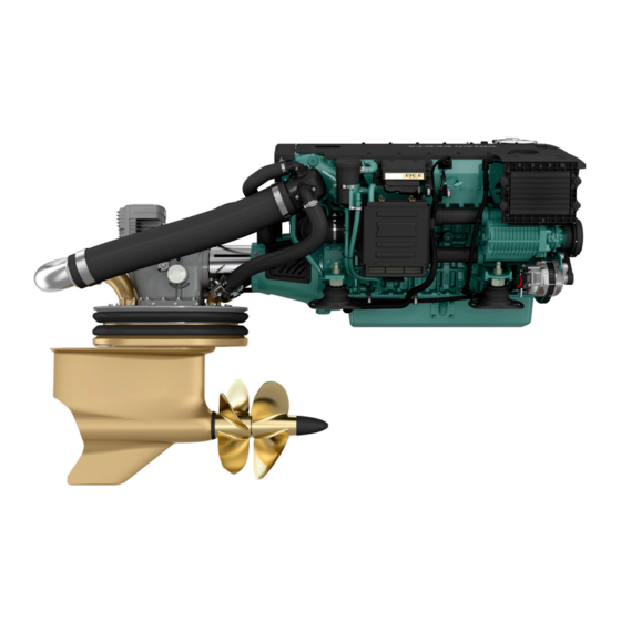
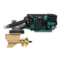
Performance System p0006599 Volvo Penta IPS overview Maneuvering and handling Volvo Penta IPS is setting a new standard: The reasons for the amazing maneuverability are: Much improved efficiency, higher top speed, The Volvo Penta IPS drive-units are steerable, reduced fuel consumption/extended range and turning and pointing the entire thrust in the great acceleration.
-
Page 13
Comfort Environmental care Volvo Penta IPS new technology leads to major The Volvo Penta IPS has been developed as a com- improvements for all comfort enhancing factors. plete system with excellent environmental perform- ance as one of the main design targets. The very high… -
Page 14: Instruments And Controls
Instruments and Controls This chapter describes the instruments, panels and controls Volvo Penta sells for your engine. If you would like to complement your instrumentation, or if your boat is equipped with instruments not described here, we ask that you contact your Volvo Penta dealer.
-
Page 15
Instruments and Controls Gauges Tachometer The tachometer displays engine speed; multiply the value shown on the dial by 1,000 to get the number of engine revolutions per minute. Boat and engine information is displayed in the tach- ometer window. Information displayed depends on engine type, the number of sensors and which acces- sories are installed. -
Page 16: Control Panel
Instruments and Controls Control Panel The control panel is used for station handling, disen- gaging the drive and to navigate the EVC system menu. Always push the buttons firmly and for at least one second. Activation button The control panel and station are activated by pushing the activation button once.
-
Page 17: Docking Station Panel
Instruments and Controls Multifunction Button With the multifunction button the instruments and pan- els backlighting is adjusted. Push the button for over a second to turn the back- lighting on or off. The backlighting can be adjusted in five stages by repeatedly pushing the multifunction button quickly (less than 1 second).
-
Page 18: Evc System Display
Instruments and Controls Alarm acknowledge button Push this button to acknowledge an alarm of a fault. A fault is always indicated with a flashing lamp above the button and a more serious faults is also indicated with a buzzer. When the fault is acknowledged the lamp will light continuously and the buzzer will silence.
-
Page 19
Instruments and Controls malfunction. The display will work but may act in an unexpected way. NOTICE! Only installed functions will be shown in the display. Display modes Press button 1–4 to view the function menu for the buttons, apperaring in the lower part of the display. Press button 1–4 to choose the desired display mode. -
Page 20
Instruments and Controls Multi, button 2 In the multi mode the information can be shown in sev- eral windows, analogue or digital. The display can show windows with different information or be divid- edto show windows and system information. To handle the system information, see chapter Instruments and Controls page 20. -
Page 21
Instruments and Controls Configuration menu Press button 5 for five seconds to enter the Configu- ration menu. Navigate with the up and down arrows, select with the right arrow. NOTICE! The port engine, or both engines must have the ignition on when display settings are made. System information System information shows the EVC-menyn and is han- dled by the knob on the control panel. -
Page 22: Evc Menu
Instruments and Controls EVC Menu The EVC menu can be shown in both the EVC system display and the tachometer display. The main menu shows operating information, the settings menu and the fault menu (only shown when a fault in the system is detected).
-
Page 23
Instruments and Controls Settings Turn the control panel wheel until the start screen for the settings menu is displayed. Press the wheel to reach the sub menus. Turn to move between the available setting functions. For further information, refer to section Settnings P0001015 menu page 102. -
Page 24: Single Lever Control
Instruments and Controls Controls Single Lever Control Maneuvering A single-lever control operates both gearshift and throttle functions with the same lever. The engine can only be started with the control lever in the neutral position. N = Neutral position. Reverse gear/drive disengaged and engine at idle.
-
Page 25: Adjusting The Friction Brake
(–) for easier movement. 5 Reinstall the plug. Joystick Volvo Penta IPS Joystick is a control used for docking and maneuvering in low speed. The joystick makes it possible to rotate the boat and maneuver the boat in different directions –…
-
Page 26
Instruments and Controls 1 Activate the docking function by pressing the dock- ing button (A) on the joystick. 2 A sound signal confirms that the docking function is active and the lamp by the docking button is lit. 3 To inactivate the function press the docking button. To confirm that the function is inactivated the signal sounds twice and the lamp goes out. -
Page 27
Instruments and Controls Maneuvering with joystick To maneuver the boat move the joystick forwards, back- wards, sideways or by turning the top of the joystick, see figure. IMPORTANT! The boat keeps moving even after the joystick is released, compensate this by moving the joystick in opposite direction. -
Page 28: Optional
Volvo Penta’s sport fish function has been developed by deep-sea fishermen. When the function is activated, the IPS units are angled outwards and the helmsman can quickly rotate and maneuver forward/backwards to follow the movement of the fish. When activated, the wheel is disconnected and the boat is maneuvered solely via the control lever.
-
Page 29
Optional Activating single-lever function 1 In order to activate the single-lever function, the control levers must be roughly the same position, max 10% difference. 2 Press the single lever button. The activation of the function is acknowledged by an acoustic signal and the lamp next to the button lighting. -
Page 30
12 V/24 V system. If the batteries begin to discharge, the ACP switches from primary to secondary protection. The IPS is then protected by the consumption of a sacrificial zinc anode installed in the ACP unit on the transom. -
Page 31
Optional • No Protection; risk of corrosion, system gives warn- ing alarm. The display switches between the two screens. Seek service for system checks. P0001218 • If the ACP is set to inactive, the system cannot iden- tify ACP status and three lines will be shown on the display. -
Page 32
To avoid fault codes, select inactive mode before lifting the boat out of the water. In this mode the ACP no longer monitors the corrosion condition, but the IPS is protected by the zinc anode. P0003049 The system is re-started when the ignition is P0003049 switched on;… -
Page 33: Starting
Starting Make a habit of visually checking the engine, engine bay and transmission before start. This will help you to discover quickly if anything abnormal has happened, or is about to happen. Also check that instruments and warning displays show normal values when you have started the engine. To minimize cold start smoke we recommend the installation of an engine heater or engine bay heater if temper- atures below +5°C (41°F) are encountered.
-
Page 34: Starting The Engine
Starting Starting the Engine Shifting, adjusting speed and performing EVC settings and calibrations is only possible at an active station. On a boat with one station the station is always active. On a boat with two or more stations the main station automatically becomes active when the EVC system is started up with the ignition key(s).
-
Page 35
Starting Check lamps Each time the ignition is turned on, all lamps in the alarm instrument are illuminated. Check that all lamps light up and go out. If a lamp flashes a fault has been registred, please refer to section Fault Han- dling page 41 for further information and reco- mended actions. -
Page 36: Operation
Operation Learn to handle the engine, controls and other equipment in a safe and proper manner before casting off on your maiden voyage. Remember to avoid sudden and extreme rudder maneuvers and gear shifts. There is a risk for passengers and crew falling over or falling overboard. WARNING! A rotating propeller can cause serious injury.
-
Page 37
Operation Maneuvering Shifting between forward and reverse should be done at idling. Shifting at higher engine speeds can be uncomfortable for passengers and cause unnecessary stress on the transmission or cause the engine to stop. If you attempt to shift gear at an excessive engine speed, a safety function cuts in automatically, and delays shifting until engine speed has fallen to 1500 rpm. -
Page 38: Helm Stations
Operation Helm Stations Changing stations 1 Put the gear in neutral. The lamp above the neutral button (1) is lit when the gear is in neutral. 2 Unlock, if locked, the station you leave by pushing the activation button (2). 3 Activate the station you change to by pressing the activation button (2).
-
Page 39: Cruising Speed
“Fault tracing” chapter. Select a propeller with greater pitch if actual engine revolutions exceed the full throttle range. Contact your Volvo Penta dealer for advice. Synchronizing Engine Speed When driving with twin engines, both the operating economy and comfort will be increased when the engines are operating at the same engine speed (rpm).
-
Page 40: Engine Shutdown
Engine Shutdown Allow the engine to run at low idle, in neutral, for a few minutes after operations are completed. In this way after- boiling is avoided at the same time as temperature equalization takes place. This is especially important when the engine has been run at high rpm or under heavy load.
-
Page 41: After Engine Shutdown
Engine Shutdown Auxiliary stop If the engine cannot be stopped in a normal procedure, it is possible to stop the engine via auxiliary stop mounted on the side of the engine. P0003709 After Engine Shutdown • Check the engine and engine bay for leakages. •…
-
Page 42: Cold Weather Precautions
Engine Shutdown Operation break with the boat in water If the boat is not used, but left in the water, the engine must be warmed up at least once every fortnight. This prevents corrosion damage in the engine. If you expect the boat to be unused for two months or more, it must be laid up, please refer to Stor- age page 98 Operation break with the boat out of water…
-
Page 43: Fault Handling
Fault Handling Despite regular maintenance according to the maintenance schedule and perfect operation conditions faults may occur which must be attended to before the boat can travel further. This chapter describes alarms and fault handling. Alarm handling Fault information from engine and EVC system If a malfunction is discovered the driver is warned by a buzzer sounding and a pop-up showing in the display.
-
Page 44
Fault Handling Acknowledging alarm 1 Push the knob on the control panel to ackowledge the alarm. The buzzer becomes silent. 2 Read the alarm or message in the pop-up. 3 Push the knob on the control panel again and the pop-up disappears. -
Page 45: Faults List
Fault Handling Faults list Is a fault registered the display shows Faults in the EVC menu along with the number of faults. Push the knob on the control panel to open the menue. Turn the knob to see all faults registred. The popup toggles between cause of fault and tasks to perform.
-
Page 46: Fault Tracing
A number of symptoms and possible causes of engine malfunctions are described in the table below. Always contact your Volvo Penta dealer if problems occur which you can not solve by yourself. NOTICE! Read through the safety advice for care and maintenance work in chapter Safety Information page 6 before starting work.
-
Page 47: Fault Code Register
Check the batteries fluid level • Check belt tension. • Please contact a Volvo Penta workshop if the fault remains. P0005024 1 Is the orange “water in fuel” lamp lit there is to much water in the water separator on the fuel pre-filter.
-
Page 48: Engine Speed
None. Action: • Empty the water trap underneath the fuel filters. Please refer to Maintenance page 74. • Please contact a Volvo Penta workshop if the fault remains. P0001200 CAUTION! Water in Fuel See Operator’s Manual Air Temperature Explanation: Charge air temperature too high.
-
Page 49: Coolant Level
Topping Up page 79. • Check that no coolant leakage occurs in auxiliary equipment connected to the engine cooling system. • Please contact a Volvo Penta workshop if the fault remains. P0005012 WARNING! Coolant Level See Opera- tor’s Manual Coolant Temperature Explanation: Coolant temperature too high.
-
Page 50: Engine Oil Level
72. P0005017 • Check that no leakage occurs. WARNING! Engine Oil Level See Oper- • Please contact a Volvo Penta workshop if the fault remains. ator’s Manual Engine Oil Pressure Explanation: Oil pressure too low. Symptom: Engine power is reduced.
-
Page 51: Battery Voltage
Check that the oil strainer is not blocked. • Check that no leakage occurs. P0005023 • Please contact a Volvo Penta workshop if the fault remains. WARNING! Transmission Oil Pressure See Operator’s Manual Battery Voltage Explanation: Battery voltage too low.
-
Page 52
86. • Check belt tension. Please refer to Drive Belt, Check and Change page 70. • Please contact a Volvo Penta workshop if the fault remains. P0005026 WARNING! Primary Battery See Oper- ator’s Manual SUS, Battery Voltage Low Explanation: Low supply voltage to SUS unit. -
Page 53
Restart engine(s). • If the engine can not be operated from the chosen station, use an alternative station. • Please contact a Volvo Penta workshop if the fault remains. P0005031 WARNING!Check Control Lever See Operator’s Manual P0005032 CAUTION!Check Control LeverSee… -
Page 54
• Restart engine(s). • If the engine can not be operated from the chosen station, use an alternative station. • Please contact a Volvo Penta workshop if the fault remains. P0005034 WARNING!Check EVC SystemSee Operator’s Manual P0005035 CAUTION!Check EVC SystemSee… -
Page 55
• Restart engine(s). • If the engine can not be operated from the chosen station, use an alternative station. • Please contact a Volvo Penta workshop if the fault remains. P0005037 WARNING!Check JoystickSee Opera- tor’s Manual P0005038 CAUTION!Check JoystickSee Opera-… -
Page 56
Fault in steering system. Symptom: Engine power is reduced. Action: • Restart engine(s). • Please contact a Volvo Penta workshop if the fault remains. P0005040 CAUTION! Limited Engine RPM See Operator’s Manual Limited steering Explanation: Fault in steering system. Symptom: Engine power is reduced. -
Page 57
Fault in steering system. Symptom: No steering. No drifting. Action: • Restart engine(s). • Please contact a Volvo Penta workshop if the fault remains. P0005043 DANGER! No Gear/Throttle, No Steer- Restart Engines See Operator’s Man- Helm Restarted Explanation: Lost active helm during crank. -
Page 58
Fault Code Register Key Failure Explanation: Key or start panel out of order. Symptom: None. Action: Please contact a Volvo Penta workshop. P0001199 CAUTION! Key FailureSee Operator’s Manual Check Multilink Explanation: Fault in multilink communication. Symptom: Possible loss of engine synchronization or loss of display(s). -
Page 59: In Case Of Emergency
In Case of Emergency In Case of Emergency Despite regular maintenance according to the mainte- nance schedule and perfect operation, faults may occur which must be attended to before the boat can travel further. This chapter contains tips for rectifying some of the possible faults.
-
Page 60: Starting Using Auxiliary Batteries
In Case of Emergency Starting Using Auxiliary Batteries WARNING! Explosion hazard. Batteries contain and give off an explosive gas which is highly flammable and explosive. A short circuit, open flame or spark could cause a vio- lent explosion. Ventilate well. WARNING! Never confuse the positive and negative poles on the batteries.
-
Page 61: Emergency Shifting
In Case of Emergency Emergency Shifting If a fault occurs which prevents gear shifting with the control levers, it is possible to shift manually using the description below. NOTICE! The following procedure can be performed with the engine(s) shut down or running. WARNING! In emergency shifting, the unit is locked in forwards operation and the revers gear can not be disengaged…
-
Page 62
In Case of Emergency Manual engagement – forward gear: 1 Undo the two connectors, marked “Secondary” and “Primary”, from the solenoid valves. 2 Remove the cap nut from the lower solenoid valve marked “P” (forward gear). 3 Release the spring loaded button by pushing and at the same time turning it 1/2 turn counter-clock- wise. -
Page 63: Emergency Alignment, Propulsion Unit
In Case of Emergency Emergency Alignment, Propulsion Unit If a fault occurs which prevents one or several propul- sion units from being operated with the steering wheel it is possible to align the propulsion unit(s) for straight forward operation manually using the description below.
-
Page 64
In Case of Emergency 2 Connect the switch and fit the red crank tool. 3 Press the switch button down and keep it pressed while turning the crank tool carefully to an end posi- tion. When the end position is reached, stop turn- ing. -
Page 65: Emergency Steering With Control Levers
In Case of Emergency 5 Remove the crank tool. Disconnect the switch by pressing down the lock and at the same time unplugg the switch by slowly wiggling it (please refer to procedure in step 1). Screw back the plug. 6 Reconnect the cable you disconnected in step 1.
-
Page 66
In Case of Emergency Steering the boat Put the control levers in forward. Use a suitable engine speed for maneuvring. The direction of the steering is determined by the use of the control levers. If the boat is to turn to starboard, reduce speed on starboard engine. -
Page 67: Maintenance Schedule
Coolant level and antifreeze mixture Drive belt (tension) Seawater filter Drive-unit, oil level Corrosion protection (space between IPS-housing and clamping ring) Instrument panel function Start and warm up engine Inspection with VODIA (Diagnostic Tool) Engine and transmission, oil / fuel / water leakage…
-
Page 68
Seawater pump impeller Sacrificial anodes (charge air cooler and heat exchanger) Corrosion protection (space between IPS-housing and clamping ring) Engine and propulsion unit. Clean and touch up paintwork as required All hoses and pipes – Check the condition and re-tighten the hose clamps… -
Page 69: Maintenance
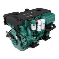
Make it impossible to start the engine by removing the start key and cutting the system voltage with the main switches. Orientation Volvo Penta IPS, starboard 1 Volvo Penta IPS, Servo Unit 2 Turbocharger 3 Crankcase ventilation filter 4 Air filter…
-
Page 70: General Inspection
Maintenance Engine, General General inspection Make a habit of visually checking the engine and engine bay before starting, and after operations when you have stopped the engine. This will help you to dis- cover abnormalities quickly, or if something is about to happen.
-
Page 71: Crankcase Ventilation, Filter Change
Maintenance Crankcase Ventilation, Filter Change 1 Unscrew the cover and remove the old filter. 2 Clean the filter cover/housing as necessary. Be careful to prevent contamination from entering the engine. 3 Install the new filter. 4 Screw the cover back in place. IMPORTANT! Scrap the old filter.
-
Page 72: Drive Belt, Check And Change
Maintenance Drive Belt, Check and Change WARNING! Stop the engine before doing any maintenance work. General Check belt tensions and condition regularly. A belt that is tensioned too tightly may damage bearings, while a belt too-loosely tensioned may slip. Check and adjust the belt after operation, while the belt is still warm.
-
Page 73: Compressor, Checking Oil
Maintenance Compressor, checking oil Checking and filling 1 Unscrew and lift up the oil dipstick. Dry the oil off. Screw the oil dipstick down as far as it will go and then unscrew and lift up. 2 Check that the oil level is between the MAX and MIN marks.
-
Page 74: Engine Oil, Change
Maintenance Lubrication System Oil change intervals can vary depending on oil grade and sulphur content of the fuel, please refer to Tech- nical Data page 115. Oil change intervals must never exceed a period of 12 months. If you want longer oil change intervals than given in the table Technical Data page 115, the condition of the oil must be checked by the oil manufacturers through regular oil testing.
-
Page 75: Oil Filter/By-Pass Filter, Change
Maintenance WARNING! Hot oil and hot surfaces can cause burns. 1 Run the engine until warm so that the oil is easier to pump. Then stop the engine and wait 10 minutes. 2 Connect the oil suction pump to the draining pipe. Pump out the oil.
-
Page 76: Engine Fuel Filter Replacement
Maintenance Fuel System Only use the grades of fuel recommended in the fuel specification, see Technical Data page 116. Always observe the greatest cleanliness during re-fuelling and work on the fuel system. All work on the unit injectors of the engine must be carried out by an authorized workshop.
-
Page 77: Fuel System, Bleeding
Maintenance Fuel system, bleeding The fuel system must be bled after a filter change, if the fuel tank has been run dry and after a long-term stoppage. IMPORTANT! Never disconnect the pressure pipe. 1 Connect a transparent hose to the bleed nipple (1).
-
Page 78
Maintenance Water in Fuel If the EVC system warns for too much water in the fuel pre-filter, the water separator needs emptying. IMPORTANT! Do not continue operating if there is water in the water separator, it can damage the engine. Draining the fuel filter 1 Stop the engine and remove the ignition key from the ignition lock. -
Page 79: Freshwater System
Water Quality page 116. Only coolant of this grade is suitable for, and approved by, Volvo Penta. The use of anti-corrosion agents alone is not permitted in Volvo Penta engines. Never use water alone as the coolant. IMPORTANT! Coolant of a suitable chemical composition must be used all year round.
-
Page 80
The coolant must be mixed with distilled, deionized water. The water must fulfill the requirements specified by Volvo Penta; refer to Water Quality page 116. It is extremely important that the system is filled with the correct coolant concentration. Mix in a separate clean vessel before filling the cooling system. -
Page 81: Freshwater System, Draining
Maintenance Coolant Level, Checking and Topping Up WARNING! Do not open the coolant filler cap when the engine is warm, except in emergencies, this could cause serious personal injury. Steam or hot fluid could spray out. 1 Turn the filler cover slowly counter-clockwise and release any pressure from the system before removing the cover completely.
-
Page 82: Seawater System
Seawater System The raw water system is the engine’s external cooling system. On IPS engines, the raw water pump sucks in water via the IPS cooling water inlet, through the IPS unit oil cooler to the raw water pump. The water then…
-
Page 83: Zinc Anodes, Check And Change
Maintenance Zinc Anodes, Check and Change WARNING! Risk of water entry. Close the seawater cocks before doing any work on the seawater system. 1 Close the sea cock(s). 2 Drain the raw water as described in Seawater Sys- tem, Draining page 80. 3 Remove the zinc anodes from the heat exchanger (1) and intercooler (2).
-
Page 84
Maintenance Seawater System, Cleaning and Inhibiting To prevent the build up of deposits and salt crystals in the seawater system it must be flushed with freshwa- ter. The system must also be preserved when the boat is going to be layed up on land for longer periods than two month. -
Page 85
Maintenance 7 The antifreeze mixture should be left in the system while the boat is not used. Before starting to use the boat again drain the mixture and clean the system using the same procedure as above. 8 Deposit antifreeze mixture at a properly designated waste site. -
Page 86: Main Switch
Maintenance Electrical System The engine is equipped with a 2-pole electrical system and an alternator. System voltage is 12V or 24V. WARNING! Always stop the engine and break the current using the main switches before working on the electrical system. Isolate shore current to the engine block heater, bat- tery charger or accessories mounted on the engine.
-
Page 87: Electrical Connections
Volvo Penta workshop. Electrical Connections Check that electrical connections are dry, free from oxide, and that they are securely tightened. Spray the connections as necessary with water-repellent spray (Volvo Penta universal oil). 7748921 04-2008…
-
Page 88: Battery, Maintenance
Maintenance Battery, Maintenance WARNING! Risk of fire and explosion. Never allow an open flame or electric sparks near the battery or batteries. WARNING! P0002107 Never confuse the positive and negative poles on the batteries. Risk of arcing and explosion. WARNING! The battery electrolyte contains extremely corrosive sulfuric acid.
-
Page 89: Battery, Charging
Maintenance Filling The electrolyte level should be 5–10 mm (0.2– 0.4”) above the cell plates in the battery. Top up with distilled water as required. After filling, the battery should be charged for at least 30 minutes by running the engine at idle. Some maintenance-free batteries have special instructions, which must be followed.
-
Page 90: Electrical Installations
Maintenance • Charge batteries if they have become discharged. During charging, unscrew the cell plugs but leave them in the plug holes. Ventilate well, especially if the batteries are charged in an enclosed space. • If the engine is not used for a longer period of time, the batteries should be fully charged, then possibly trickle charged (please refer to the battery manu- facturer’s recommendations).
-
Page 91
Maintenance Always consider the following: 1 If shore power is connected it must always be ground protected ashore, never in the boat. Fur- thermore, the shore power installation should be equipped with a ground fault interrupter. The shore power installation (transformer, inverter, battery charger etc.) must be designed for marine use where the high-tension side is galvanically separated from the low-tension side. -
Page 92
While checking the oil level, ensure there are no signs of water dilution. The oil should have a golden brown hue. If the oil is thin and greyish it is probable water diluted. If so, always let the propulsion unit be checked by a Volvo Penta workshop. 7748921 04-2008… -
Page 93: Changing Oil And Filter
Check that the space between the drive housing and the lock plate is completely covered by corrosion pro- tection, Volvo Penta part # 9510227. Follow the instructions below if the protection needs renewing: 1 Clean and dry the surface between the housing and the lock plate.
-
Page 94: Sacrificial Anodes
Maintenance Inspection/replacing corrosion protection – Sacrificial anodes Check the sacrificial anodes regularly. There are two anodes per stern drive; one is fixed to the drive and the other to the transom. Refer to the illustrations. Replace an anode when approximately 1/3 of it has corroded away.
-
Page 95
Maintenance Inspect the drive unit paint Volvo Penta recommends ”Prop speed ®” coating. Instructions regarding the application of ”Prop speed ®” coating are included with the product. Inspect the coating every year and scrape away any loose coating and apply new. -
Page 96
Maintenance Propeller WARNING! Make sure the engine can not start during work on propeller(s); remove ignition key(s) and shift drive into forward or reverse. NOTICE! Damaged propellers should be replaced immediately otherwise there is high risk of serious damage to the propulsion unit. Operating the boat with a damaged propeller should be undertaken with extreme care and only at reduced engine speeds. -
Page 97
Maintenance 3 Undo the locking ring with the accompanying spe- cial tool by unscrew the four socket cap screws (2). Remove nut (B) and locking ring (3). Remove the forward propeller from the propeller shaft. 4 Undo the locking ring for the aft propeller with the accompanying special tool by unscrew the four socket cap screws (4). -
Page 98
Maintenance Assemble propellers 1 Apply water-resistant grease, P/N 828250 to the splines and threads on both propeller shafts. 2 Install the aft propeller. Then install the aft nut (C) and tighten it by hand until it bottoms. Install locking ring (5). Tighten the locking ring with the accompa- nying special tool and four socket cap screws (4). -
Page 99
Maintenance 3 Install the forward propeller on the propeller shaft. Tighten nut (A) by hand and install locking ring (3). Tighten the locking ring with the accompanying special tool and four socket cap screws (2). Torque 24-28 Nm (17.7-20.7 ft. lb.). 4 IMPORTANT! Tighten the screw (D) until it bottoms. -
Page 100: Storage
Storage Short Term Storage If the boat is not going to be used for a shorter period, the engines must be run up to normal operating tem- perature at least once every 14 days. This prevents corrosion in the engines. WARNING! If the engines must be run up to normal operating tem- perature with the boat kept up on land, make sure to…
-
Page 101: Long Term Storage
Storage Long Term Storage If the boat is not going to be used for a longer period than two months, either left in the water or layed up on land, a long-term preservation of the engine and pro- pulsion unit should be carried out. This ensures that the engine and propulsion unit are kept in good condi- tion and that no damage arises.
-
Page 102
Storage • Clean the outside of the engine. Touch up any dam- aged areas of paintwork with Volvo Penta original paint. IMPORTANT! Never use a high-pressure washer when washing the engine and never point highpressure water jets directly at seals, rubber hoses or electrical compo- nents, as this could cause serious damage. -
Page 103: Bringing Out Of Storage
Storage Bringing Out of Storage The following should be carried out on each propulsion unit with the boat out of the water: • Paint the hull. • Check the sacrificial anode on the propulsion unit If there is less than 2/3 of the anode left, it must be replaced.
-
Page 104: Calibration And Settings
2 Press the wheel to access the settings menu. 3 Navigate by turning the wheel. P0001015 Depth Alarm Setting the depth alarm for the Volvo Penta echo soun- der. The setting need only be entered at one display, at one station.
-
Page 105
Calibration and Settings 4 Turn to Set Level. Press the wheel to access adjustment of depth level alarm. Turn the wheel to set the alarm depth, i.e. the depth when the alarm should begin sounding. Press the wheel to confirm the set depth. The depth alarm is dependent on depth compen- sation (offset depth). -
Page 106: Trip Reset
Calibration and Settings Depth alarm popup window When the depth is less than the alarm level, the popup window will display intermittently, followed by the alarm signal. The pop-up window will be displayed every 30 seconds until the depth is greater than the alarm level. Confirm the selection by depressing the navigation wheel.
-
Page 107: My View
Calibration and Settings My View In My view it is possible to select the operating infor- mation to be displayed in the main menu. The type of information that may be selected depends on the functions installed. P0001016 1 Turn to My View in the settings menu. Press to reach the submenu.
-
Page 108: Evc Info
Calibration and Settings Setting the ACP protection position. 1 Turn until ACP is shown in the settings menu. Press to reach the submenu. P0001022 2 Turn to the desired position Normal, Chlorine Gas Free or Inactive. Press the wheel to confirm the selection. P0001021 EVC Info Information regarding accessories, components and…
-
Page 109: Information Beep
Calibration and Settings 1 Activate the station. 2 Turn until Units is shown in the settings menu. Press to reach the units menu. 3 Turn to US or Metric; press the wheel and select US or Metric. P0001036 Press the wheel to confirm the selection. 4 Turn to Distance;…
-
Page 110: Fuel Tank
Calibration and Settings Fuel Tank There are two alternative methods for calibrating the level sensor in the fuel tank. Full Fuel Tank Calibra- tion is an approximate method, while Fuel Multipoint Calibration provides more precise results. Multi-point calibration is a prerequisite if the trip computer is to show fully accurate information.
-
Page 111: Speed Factor
Calibration and Settings Full Fuel Tank Calibration For this method the tank must be full and calibration of the fuel level sensor takes place in one step. This means that the fuel level value will be approximate, and therefore all trip data based on remaining fuel must be seen as approximate values.
-
Page 112
Calibration and Settings Joystick Joystick calibration need only be carried out if boat movements do not correspond to joystick movements. When calibrating the joystick the boat must be driven on open waters in safe conditions. Avoid calibrating in high winds or currents that can influence the result of the calibration. -
Page 113
4 Simultaneously press both buttons on the joystick for 5 sec. to reach calibration mode. 5 Calibration mode is confirmed by an audible signal and by both lamps on the joystick and the neutral button lamps on the control panel flashing. 6 Move the joystick sideways as far as it will go in one direction. -
Page 114
Calibration and Settings 8 An audible signal and both lamps on the joystick and the neutral button lamps on the control panel will light up to confirm that calibration is complete and stored. The system is now in docking mode. 9 When the joystick is returned to the central position the lamps stop flashing;… -
Page 115
Calibration and Settings 4 Calibration mode is confirmed by an audible signal and by both lamps on the joystick and the neutral button lamps on the control panel flashing. 5 Press the docking button. Calibration is now reset, which is confirmed by an audible signal. The sys- tem is now in docking mode. -
Page 116: Technical Data
Technical Data Engines Engine, General Volvo Penta IPS system designation D4 — See table below D6 — See table below Engine model/after market designation See table below See table below Crankshaft power kW (hp)* See table below See table below…
-
Page 117
SAE 15W/40 (See table) Compressor, oil Oil volume 0.1 liters (0.2 US pint) Oil grade Volvo Penta, part no. 1141641 Sulphur content in fuel, by weight Oil grade < 0.5 – 1.0% more than 1.0% Oil change interval: Reached first in operation:… -
Page 118: Fuel Specification
Technical Data Viscosity Select the viscosity according to the table. The temperature values refer to stable ambient tem- peratures. * SAE 5W/30 refers to synthetic or semi-synthetic oils. Fuel System Fuel specification The fuel must comply with national and international standards for commercially supplied fuels, such as: EN 590 (with national environment and cold requirements) ASTM D 975 No 1-D and 2-D JIS KK 2204…
-
Page 119
= 0.0434 lb/in g/cm = 0.0434 lb/in NOTICE! * Applies to batteries with tropical acid. Sterndrive Volvo Penta IPS system designation IPS 350/400 IPS 400/450/500 IPS 600 Oil volume, approx. 14 liters (3.7 US gals) 14 liters (3.7 US gals) 14 liters (3.7 US gals) Oil volume difference MIN –… -
Page 120: Identification Numbers
Technical Data Identification Numbers There are type plates on the engine and transmission, marked with identification numbers. This information must always be used as reference when service and spare parts are ordered. You will probably find similar plates on your boat and its equipment. Note this information below, make a copy of the page and store it in a safe place, so that you can have the information available if the boat is stolen.
-
Page 121
…………….with integral exhaust Engine(s) models covered by this declaration EC Type certificate number Volvo Penta IPS 350 (D4-260) Volvo Penta IPS 400 (D4-300) ……..SDVOLV005 (noise) EXVOLV001 (exhaust) Volvo Penta IPS 400 (D6-310) Volvo Penta IPS 450 (D6-330) Volvo Penta IPS 500 (D6-370) Volvo Penta IPS 600 (D6-435) ……..SDVOLV004 (noise) -
Page 122: Alphabetical Index
Units…………..106 Display Contrast………… 105 Water Quality…………116 Docking Station Panel……….15 Drive……………. 90 Volvo Penta IPS — Inboard Performance Sys- Drive Belt, Check and Change…….. 70 tem…………….10 Electrical Connections………. 85 Zinc Anodes, Check and Change……81 Electrical Installations……….88 Electrical System……….
-
Page 123
NOTICE: The free-of-charge Operator’s Manual offer is valid for 12 months after delivery. Fill in your name, postal address, email address and desired language. Publication Reference: 7748921 Name: Address: Country: E-mail: English Dansk Svenska Suomi Deutsch Português Français Ελληνικά Español Русско…

На этой странице вы можете скачать руководства пользователя (их еще называют инструкция оператора) для двигателей Volvo Penta.
Важно! Если нужное руководство не нашлось, напишите на manual@unisail.ru и мы пришлем его вам бесплатно в электронном виде. В письме укажите:
— серийный номер двигателя (предпочтительно)
или
— модель и год выпуска.
Мы постараемся прислать инструкцию в течение одного рабочего дня.
Мы не высылаем инструкции по ремонту двигателей.
Обратите внимание! Инструкции на русском языке существуют не для всех моделей двигателей Вольво Пента. В случае, если инструкция на русском недоступна, мы отправим вам ее на английском языке (если вам больше подойдет другой язык, то на нем тоже поищем).
| Модель двигателя / название публикации | Дата публикации | Язык | |
| Сервисная книжка Volvo Penta | 2014 | русский* | скачать |
|
Volvo Penta D1, D2 |
2014-06 | русский | скачать |
| Volvo Penta D1, D2 | 2009-06 | русский | скачать |
| Volvo Penta D1, D2 | 2007-12 | русский | скачать |
| Volvo Penta D1, D2 | 2007-07 | русский | скачать |
| Volvo Penta D2 | 2014-06 | русский | скачать |
| Volvo Penta D2 (версия 1) | 2009-06 | русский | скачать |
| Volvo Penta D2 (версия 2) | 2009-06 | русский | скачать |
| Volvo Penta D3 (доп. для SOLAS) | 2014-11 | русский* | скачать |
| Volvo Penta D3 | 2014-06 | русский | скачать |
| Volvo Penta D3 | 2012-02 | русский | скачать |
| Volvo Penta D3 | 2010-07 | русский | скачать |
| Volvo Penta D3 | 2010-01 | русский | скачать |
| Volvo Penta D3 | 2009-05 | русский | скачать |
| Volvo Penta D3 (доп. для SOLAS) | 2007-04 | русский* | скачать |
| Volvo Penta D3 | 2006-10 | русский | скачать |
| Volvo Penta D3 | 2005-12 | русский | скачать |
| Volvo Penta D4, D6 (доп. для SOLAS) | 2015-03 | русский | скачать |
| Volvo Penta D4, D6 | 2014-12 | русский | скачать |
| Volvo Penta D4, D6 | 2011-05 | русский | скачать |
| Volvo Penta D4, D6 | 2009-08 | русский | скачать |
| Volvo Penta D4, D6 | 2009-06 | русский | скачать |
| Volvo Penta D4, D6 | 2007-06 | русский | скачать |
| Volvo Penta D4, D6 (доп. для SOLAS) | 2006-06 | русский | скачать |
| Volvo Penta D4, D6 | 2006-05 | русский | скачать |
| Volvo Penta D4, D6 | 2005-06 | русский | скачать |
| Напишите на manual@unisail.ru, если не нашли то, что ищете. Пришлем в электронном виде бесплатно! Условия в начале этой страницы. | |||
Все файлы в формате PDF. Для просмотра файлов в этом формате воспользуйтесь программой Adobe Reader, скачать которую можно здесь: https://get.adobe.com/ru/reader/.
- Manuals
- Brands
- Volvo Penta Manuals
- Engine
ManualsLib has more than 684 Volvo Penta Engine manuals
Click on an alphabet below to see the full list of models starting with that letter:
1
2
3
4
5
7
8
A
B
D
H
I
K
M
P
S
T
V
Popular manuals
128 pages
D4 Operator’s Manual
136 pages
3.0GLP-C Owner’s Manual

96 pages
31 Series Workshop Manual
108 pages
D2-55 Workshop Manual
88 pages
3.0GS/SX Owner’s Manual
132 pages
MD22 Workshop Manual
104 pages
KAD/KAMD44P Operator’s Manual
74 pages
AQ145A Workshop Manual
238 pages
MD Instruction Manual

140 pages
IPS User Manual
133 pages
D3 Operator’s Manual
65 pages
PENTA — MANUAL SERVICE Manual
41 pages
MD7A Instruction Book
124 pages
IPS Operator’s Manual
89 pages
MS2 Workshop Manual
137 pages
D1-13 Workshop Manual
138 pages
D4 Series Operator’s Manual

64 pages
MD2010 Operator’s Manual
122 pages
TD520GE Workshop Manual
122 pages
V6 Series Operator’s Manual
Models
Document Type
1
120S

Workshop Manual
120S-B
Workshop Manual
120S-C
Workshop Manual
120S-D
Workshop Manual
120S-E
Workshop Manual
13L
Operator’s Manual
2
2001
Owner’s Manual • Workshop Manual
2002
Owner’s Manual • Workshop Manual
2003
Owner’s Manual • Workshop Manual
2003T
Owner’s Manual • Workshop Manual
21182210
Operator’s Manual
21182212
Operator’s Manual
21182213
Operator’s Manual
21182215
Operator’s Manual
21189867
Operator’s Manual
21301406
Operator’s Manual
21301407
Operator’s Manual
21301408
Operator’s Manual
230
Workshop Manual • Workshop Manual
250
Workshop Manual • Workshop Manual
251DOHC
Workshop Manual • Workshop Manual
3
3.0 GS
Operator’s Manual
3.0GL-B
Operator’s Manual
3.0GL-C
Operator’s Manual
3.0GLP-C
Owner’s Manual
3.0GLP-J
Operator’s Manual
3.0GS/SX
Owner’s Manual
3.0GXi-J
Operator’s Manual
3.0GXiC-J
Operator’s Manual
300 Series
Workshop Manual
31 Series
Workshop Manual • Instruction Book
32 Series
Workshop Manual • Instruction Book
3869351
Operator’s Manual
3869352
Operator’s Manual
3869353
Operator’s Manual
3869354
Operator’s Manual
3869355
Operator’s Manual
3869356
Operator’s Manual
3869388
Operator’s Manual
3869389
Operator’s Manual
3869390
Operator’s Manual
3869391
Operator’s Manual
3869393
Operator’s Manual
3869397
Operator’s Manual
3869399
Operator’s Manual
3869400
Operator’s Manual
3869403
Operator’s Manual
3869404
Operator’s Manual
3869407
Operator’s Manual
3869408
Operator’s Manual
3869411
Operator’s Manual
3869412
Operator’s Manual
3869415
Operator’s Manual
3869416
Operator’s Manual
3869431
Operator’s Manual
3869433
Operator’s Manual
3869435
Operator’s Manual
3869437
Operator’s Manual
3869439
Operator’s Manual
3869446
Operator’s Manual
3869447
Operator’s Manual
3869448
Operator’s Manual
3869449
Operator’s Manual
3869450
Operator’s Manual
3869459
Operator’s Manual
3869461
Operator’s Manual
4
4.3 Gi
Operator’s Manual
4.3 Gi/PJX
Owner’s Manual
4.3 GL
Operator’s Manual
4.3Gi/DP-S
Owner’s Manual
4.3Gi/SX
Owner’s Manual
4.3GL-A
Operator’s Manual
4.3GL-D
Owner’s Manual
4.3GL-J
Operator’s Manual
4.3GL/DP-S
Owner’s Manual
4.3GL/SX
Owner’s Manual
4.3GS/DP-S
Owner’s Manual
4.3GS/SX
Owner’s Manual
4.3GXI-A
Operator’s Manual
4.3GXI-B
Operator’s Manual
4.3GXI-BF
Operator’s Manual
4.3GXi-E
Owner’s Manual
4.3GXi-EF
Owner’s Manual
4.3GXi-J
Operator’s Manual
4.3OSi-B
Operator’s Manual
4.3OSi-BF
Operator’s Manual
4.3OSi-C
Operator’s Manual
4.3OSi-CF
Operator’s Manual
41 Series
Workshop Manual • Instruction Book
42 Series
Workshop Manual • Instruction Book
43 Series
Workshop Manual • Instruction Book
44 Series
Workshop Manual
5
5.0 Gi
Operator’s Manual
5.0 GL
Operator’s Manual • Manual
5.0 GXi
Manual
5.0 GXiE-J
Operator’s Manual
5.0 GXiE-JF
Operator’s Manual
5.0 OSi
Manual
5.0Gi/DP-S
Owner’s Manual
5.0Gi/SX
Owner’s Manual
5.0GL-A/B
Operator’s Manual
5.0GL-E
Owner’s Manual
5.0GL-J
Operator’s Manual
5.0GL/DP-S
Owner’s Manual
5.0GL/SX
Owner’s Manual
5.0GXI-A
Operator’s Manual
5.0GXI-B
Operator’s Manual
5.0GXI-BF
Operator’s Manual
5.0GXi-E
Owner’s Manual
5.0GXi-EF
Owner’s Manual
5.0GXi-J
Operator’s Manual
5.0GXi-JF
Operator’s Manual
5.0GXiC-J
Operator’s Manual
5.0GXiCE-M
Operator’s Manual
5.0GXiCE-MF
Operator’s Manual
5.0OSi-B
Operator’s Manual
5.0OSi-BF
Operator’s Manual
5.0OSi-C
Operator’s Manual
5.0Si-CF
Operator’s Manual
5.7 Gi
Manual
5.7 GiE-300-J
Operator’s Manual
5.7 GiE-300-JF
Operator’s Manual
5.7 GS
Operator’s Manual
5.7 GXi
Manual
5.7 GXiE-J
Operator’s Manual
5.7 GXiE-JF
Operator’s Manual
5.7 OSi
Manual
5.7 OSXi
Manual
5.7GI-A
Operator’s Manual
5.7GI-B
Operator’s Manual
5.7GI-BF
Operator’s Manual
5.7Gi-E
Owner’s Manual
5.7Gi-EF
Owner’s Manual
5.7Gi300-J
Operator’s Manual
5.7Gi300-JF
Operator’s Manual
5.7GiC-300-J
Operator’s Manual
5.7GiC-300-JF
Operator’s Manual
5.7GiCE-300-M
Operator’s Manual
5.7GiCE-300-MF
Operator’s Manual
5.7GL-A/B
Operator’s Manual
5.7GS/DP-S
Owner’s Manual
5.7GS/SX
Owner’s Manual
5.7GSi
Operator’s Manual
5.7GSi/DP-S
Owner’s Manual
5.7GXI-B
Operator’s Manual
5.7GXI-C
Operator’s Manual
5.7GXI-CF
Operator’s Manual
5.7GXi-F
Owner’s Manual
5.7GXi-FF
Owner’s Manual
5.7GXi-J
Operator’s Manual
5.7GXi-JF
Operator’s Manual
5.7GXiC-J
Operator’s Manual
5.7GXiC-JF
Operator’s Manual
5.7GXiCE-M
Operator’s Manual
5.7GXiCE-MF
Operator’s Manual
5.7OSi-A
Operator’s Manual
5.7OSi-AF
Operator’s Manual
5.7OSi-B
Operator’s Manual
5.7OSi-BF
Operator’s Manual
5.7OSXi-A
Operator’s Manual
5.7OSXi-AF
Operator’s Manual
5.7OSXi-B
Operator’s Manual
5.7OSXi-BF
Operator’s Manual
7
7.4 Gi
Owner’s Manual • Operator’s Manual
7.4 GL
Owner’s Manual
7.4 GSi
Operator’s Manual
8
8.1 GiE-J
Operator’s Manual
8.1 GiE-JF
Operator’s Manual
8.1 GXiE-J
Operator’s Manual
8.1 GXiE-JF
Operator’s Manual
8.1GI-B
Operator’s Manual
8.1Gi-F
Owner’s Manual
8.1Gi-FF
Owner’s Manual
8.1Gi-J
Operator’s Manual
8.1Gi-JF
Operator’s Manual
8.1GiC-J
Operator’s Manual
8.1GiC-JF
Operator’s Manual
8.1GiCE-M
Operator’s Manual
8.1GiCE-MF
Operator’s Manual
8.1GXI-A
Operator’s Manual
8.1GXi-E
Owner’s Manual
8.1GXi-EF
Owner’s Manual
8.1GXi-J
Operator’s Manual
8.1GXi-JF
Operator’s Manual
8.2 GL
Owner’s Manual
8.2 GSi
Operator’s Manual
A
AD31
Owner’s Manual • Instruction Manual • Owner’s Manual
AD31B
Workshop Manual
AD31D
Workshop Manual
AD31L
Workshop Manual • Instruction Book
AD31L-A
Workshop Manual
AD31P
Workshop Manual • Instruction Book
AD31P-A
Workshop Manual
AD41
Owner’s Manual • Instruction Manual • Owner’s Manual
AD41B
Workshop Manual
AD41D
Workshop Manual
AD41L
Instruction Book
AD41L-A
Workshop Manual
AD41P
Workshop Manual • Instruction Book
AD41P-A
Workshop Manual
AQ100
Operator’s Manual
AQ105A
Workshop Manual
AQ110
Operator’s Manual
AQ115A
Workshop Manual
AQ120
Operator’s Manual
AQ125A
Workshop Manual
AQ125B
Workshop Manual
AQ130A
Workshop Manual
AQ130B
Workshop Manual
AQ130C
Workshop Manual
AQ131
Workshop Manual • Workshop Manual
AQ145A
Workshop Manual
AQ145B
Workshop Manual
AQ151
Workshop Manual • Workshop Manual
AQ165A
Workshop Manual
AQ170A
Workshop Manual
AQ170B
Workshop Manual
AQ170C
Workshop Manual
AQ171
Workshop Manual • Workshop Manual
AQ205
Operator’s Manual
AQ211
Operator’s Manual
AQ231
Operator’s Manual
AQ271
Operator’s Manual
AQ311
Operator’s Manual
AQAD30/DP
Instruction Book
AQAD40/290
Instruction Book
AQAD40/DP
Instruction Book
AQD70C
Instruction Book
AQD70D
Instruction Book
AQUAMATIC 110-100
Operator’s Manual • Operator’s Manual
AQUAMATIC 120-100
Operator’s Manual • Operator’s Manual
AQUAMATIC 95-100
Operator’s Manual • Operator’s Manual
B
BB231
Operator’s Manual
BB261
Operator’s Manual
D
D
Instruction Manual
D1 Series
Operator’s Manual • Operator’s Manual • Service Manual
D1-13
Operator’s Manual • Installation Instructions Manual • Operator’s Manual • Installation Manual • Workshop Manual • Operator’s Manual • Installation Instructions Manual • Workshop Manual • Installation Manual
D1-20
Operator’s Manual • Installation Instructions Manual • Operator’s Manual • Installation Manual • Workshop Manual • Operator’s Manual • Installation Instructions Manual • Workshop Manual • Installation Manual
D1-30
Operator’s Manual • Installation Instructions Manual • Operator’s Manual • Installation Manual • Workshop Manual • Operator’s Manual • Installation Instructions Manual • Workshop Manual • Installation Manual
D11
Operator’s Manual
D11/IPS20
Operator’s Manual
D12
Operator’s Manual
D12-615
Operator’s Manual
D12-650
Operator’s Manual
D12-675
Operator’s Manual
D12-715
Operator’s Manual
D12-AUX
Operator’s Manual
D13 MH RC
Operator’s Manual
D13 MP
Operator’s Manual
D13 Series
Operator’s Manual • Operator’s Manual • Operator’s Manual
D13-300
Operator’s Manual
D13-400
Operator’s Manual
D13-450
Operator’s Manual
D13-500
Operator’s Manual
D13-550
Operator’s Manual
D13-600
Operator’s Manual
D13-700
Operator’s Manual
D13-800
Operator’s Manual
D13-900
Operator’s Manual
D13B MH
Operator’s Manual
D16
Operator’s Manual • Operator’s Manual
D16 MH
User Manual • Operator’s Manual
D2 Series
Operator’s Manual • Operator’s Manual • Operator’s Manual • Service Manual
D2-40
Operator’s Manual • Installation Instructions Manual • Operator’s Manual • Installation Manual • Workshop Manual • Operator’s Manual • Installation Instructions Manual • Workshop Manual • Installation Manual
D2-55
Operator’s Manual • Operator’s Manual • Workshop Manual • Installation Manual • Installation Instructions Manual • Installation Manual
D2-75
Operator’s Manual • Operator’s Manual • Workshop Manual • Installation Manual • Installation Instructions Manual • Installation Manual
D25A MS
Operator’s Manual
D25A MT
Operator’s Manual
D3
Operator’s Manual • Operator’s Manual • Operator’s Manual
D3 290/DP
Installation Instructions Manual
D3-110i
Operator’s Manual • Operator’s Manual
D3-110i-A
Operator’s Manual
D3-130A
Operator’s Manual • Operator’s Manual
D3-130A-A
Operator’s Manual
D3-130i
Operator’s Manual • Operator’s Manual
D3-130i-A
Operator’s Manual
D3-160A
Operator’s Manual • Operator’s Manual
D3-160A-A
Operator’s Manual
D3-160i
Operator’s Manual • Operator’s Manual
D3-160i-A
Operator’s Manual
D3-190A
Operator’s Manual • Operator’s Manual
D3-190i
Operator’s Manual • Operator’s Manual
D3-SOLAS
Supplement To Operators Manual
D30A MS
Operator’s Manual
D30A MT
Operator’s Manual
D34A MS
Operator’s Manual
D34A MT
Operator’s Manual
D4
Operator’s Manual • Operator’s Manual • Operator’s Manual • Operator’s Manual • Operator’s Manual • Operator’s Manual • Operator’s Manual • Service And Maintenance Manual
D4-150A
Operator’s Manual
D4-175I
Operator’s Manual
D4-180I
Operator’s Manual
D4-225A
Operator’s Manual
D4-225I
Operator’s Manual
D4-230A
Operator’s Manual
D4-230I
Operator’s Manual
D4-260
Operator’s Manual
D4-260A
Operator’s Manual
D4-260I
Operator’s Manual
D4-270A
Operator’s Manual
D4-270I
Operator’s Manual
D4-300
Operator’s Manual
D4-300A
Operator’s Manual • Operator’s Manual
D4-300I
Operator’s Manual • Operator’s Manual
D4-320A
Operator’s Manual
D4-320I
Operator’s Manual
D4-SOLAS
Operator’s Manual
D41B
Workshop Manual
D41D
Workshop Manual
D41L
Instruction Book
D41L-A
Workshop Manual
D5
Operator’s Manual
D6
Operator’s Manual • Operator’s Manual • Operator’s Manual • Operator’s Manual • Operator’s Manual • Operator’s Manual • Operator’s Manual • Service And Maintenance Manual
D6-280A
Operator’s Manual
D6-280I
Operator’s Manual
D6-300A
Operator’s Manual
D6-300I
Operator’s Manual
D6-310
Operator’s Manual
D6-310A
Operator’s Manual
D6-310I
Operator’s Manual
D6-330
Operator’s Manual
D6-330A
Operator’s Manual
D6-330I
Operator’s Manual
D6-340A
Operator’s Manual
D6-340I
Operator’s Manual
D6-370
Operator’s Manual
D6-370A
Operator’s Manual
D6-370I
Operator’s Manual
D6-380A
Operator’s Manual
D6-380I
Operator’s Manual
D6-400A
Operator’s Manual • Operator’s Manual
D6-435
Operator’s Manual
D6-435I
Operator’s Manual
D6-440A
Operator’s Manual
D6-440I
Operator’s Manual
D6-440I-WJ
Operator’s Manual
D6-480A
Operator’s Manual
D6-480I
Operator’s Manual
D6-480I-WJ
Operator’s Manual
D6-SOLAS
Operator’s Manual
D65A MS
Workshop Manual
D65A MT
Workshop Manual
D7
Operator’s Manual
D8 2020
Operator’s Manual
D9 MH
User Manual • Operator’s Manual
D9-425
Operator’s Manual
D9-500
Operator’s Manual
D9-575
Operator’s Manual
DPS-A
Workshop Manual • Operator’s Manual • Operator’s Manual
DPX 385
Operator’s Manual
DPX 415
Operator’s Manual
DPX 500
Instruction Book
DPX 600
Instruction Book
DPX375
Operator’s Manual
DPX420
Operator’s Manual
H
HU series
Workshop Manual
I
IPS
Operator’s Manual • User Manual • Installation And System Connections
IPS 3
Installation Reference Manual
IPS 350
Operator’s Manual • Operator’s Manual • Operator’s Manual • Installations
IPS 400
Operator’s Manual • Operator’s Manual • Operator’s Manual • Installations
IPS 450
Operator’s Manual • Operator’s Manual • Operator’s Manual • Installations
IPS 500
Operator’s Manual • Operator’s Manual • Operator’s Manual • Installations
IPS 600
Operator’s Manual • Operator’s Manual • Operator’s Manual • Installations
IPS20
Installation Instructions Manual • Installation Instructions Manual
IPS30
Installation Instructions Manual • Installation Instructions Manual
IPS800
Operator’s Manual
IPS900
Operator’s Manual
K
KAD/KAMD300
Operator’s Manual
KAD/KAMD44P
Operator’s Manual
KAD300-A
Workshop Manual
KAD32P
Workshop Manual • Workshop Manual
KAD42
Owner’s Manual • Owner’s Manual
KAD42/DPX
Owner’s Manual
KAD42A
Workshop Manual • Workshop Manual
KAD42B
Workshop Manual • Workshop Manual
KAD42L
Instruction Book
KAD42P
Workshop Manual • Workshop Manual • Instruction Book
KAD43P
Workshop Manual • Workshop Manual
KAD44P
Workshop Manual
KAD44P-A
Workshop Manual
KAD44P-B
Workshop Manual
KAD44P-C
Workshop Manual
KAMD300
Installation Manual
KAMD300-A
Workshop Manual
KAMD42
Owner’s Manual • Owner’s Manual
KAMD42A
Workshop Manual • Workshop Manual
KAMD42B
Workshop Manual • Workshop Manual
KAMD42L
Instruction Book
KAMD42P
Workshop Manual • Workshop Manual • Instruction Book
KAMD43
Installation Manual
KAMD43P
Workshop Manual • Workshop Manual
KAMD44
Installation Manual
KAMD44P
Workshop Manual
KAMD44P-A
Workshop Manual
KAMD44P-B
Workshop Manual
KAMD44P-C
Workshop Manual
M
M2.04
Installation Instructions Manual
M2.06
Installation Instructions Manual
M2.C5
Installation Instructions Manual
M2.D5
Installation Instructions Manual
M3.09
Installation Instructions Manual
M3.10
Installation Instructions Manual
M4.14
Installation Instructions Manual
M4.15
Installation Instructions Manual
M4.17
Installation Instructions Manual
MB 10 A
Instruction Book
MD
Instruction Manual
MD 11C/110S
Instruction Book
MD 17C/110S
Instruction Book
MD1B
Workshop Manual • Instruction Book
MD2010
Operator’s Manual • Instruction Book • Instruction Book
MD2020
Operator’s Manual • Instruction Book • Instruction Book
MD2030
Operator’s Manual • Instruction Book • Instruction Book
MD2040
Operator’s Manual • Instruction Book • Instruction Book
MD21A
Operator’s Manual
MD22
Instruction Book • Workshop Manual
MD22L
Instruction Book
MD29A
Operator’s Manual
MD2B
Workshop Manual • Instruction Book
MD30/MS2
Instruction Book
MD30/MS2V
Instruction Book
MD31A
Workshop Manual
MD3B
Workshop Manual • Instruction Book
MD6A
Workshop Manual
MD7A
Workshop Manual • Instruction Book
MD7A/110S
Instruction Book
MS10
Installation Instructions Manual
MS15
Installation Instructions Manual
MS2
Workshop Manual
MS2A-D
Workshop Manual
MS2A-E
Workshop Manual
MS2B-A
Workshop Manual
MS2B-L
Workshop Manual
MS2L-D
Workshop Manual
MS2L-E
Workshop Manual
MS2V
Workshop Manual
P
P4.4.19
Installation Instructions Manual
PENTA
Operator’s Manual • Manual • Owner’s Manual • Launch Manual
S
SX-A
Workshop Manual • Operator’s Manual • Operator’s Manual
T
TAD1170
Operator’s Manual
TAD1170VE
Operator’s Manual
TAD1171VE
Operator’s Manual
TAD1172VE
Operator’s Manual • Operator’s Manual
TAD1240GE
Operator’s Manual • Technical Description
TAD1241GE
Operator’s Manual • Technical Description
TAD1241VE
Operator’s Manual • Technical Description
TAD1242GE
Technical Description • Operator’s Manual • Technical Description
TAD1242VE
Operator’s Manual • Technical Description
TAD1340VE
Operator’s Manual
TAD1341GE
Operator’s Manual
TAD1341VE
Operator’s Manual
TAD1342GE
Operator’s Manual
TAD1342VE
Operator’s Manual
TAD1343GE
Operator’s Manual
TAD1343VE
Operator’s Manual
TAD1344GE
Operator’s Manual
TAD1344VE
Operator’s Manual
TAD1345GE
Operator’s Manual
TAD1345VE
Operator’s Manual
TAD1350GE
Operator’s Manual
TAD1350VE
Operator’s Manual
TAD1351GE
Operator’s Manual
TAD1351VE
Operator’s Manual
TAD1352GE
Operator’s Manual
TAD1352VE
Operator’s Manual
TAD1353GE
Operator’s Manual
TAD1353VE
Operator’s Manual
TAD1354GE
Operator’s Manual
TAD1355GE
Operator’s Manual
TAD1381VE
Operator’s Manual
TAD1382VE
Operator’s Manual
TAD1383VE
Operator’s Manual
TAD1384VE
Operator’s Manual
TAD1385VE
Operator’s Manual
TAD1630G
Workshop Manual
TAD1630GE
Workshop Manual
TAD1630P
Workshop Manual
TAD1630V
Workshop Manual
TAD1631G
Workshop Manual
TAD1631GE
Workshop Manual
TAD1640GE
Operator’s Manual
TAD1640GE-B
Operator’s Manual
TAD1640VE-B
Operator’s Manual
TAD1641GE
Operator’s Manual
TAD1641GE-B
Operator’s Manual
TAD1641VE
Operator’s Manual
TAD1641VE-B
Operator’s Manual
TAD1642GE
Operator’s Manual
TAD1642GE-B
Operator’s Manual
TAD1642VE
Operator’s Manual
TAD1642VE-B
Operator’s Manual
TAD1643VE
Operator’s Manual • Operator’s Manual
TAD1643VE-B
Operator’s Manual
TAD1650GE
Operator’s Manual • Operator’s Manual
TAD1650VE
Operator’s Manual • Operator’s Manual
TAD1650VE-B
Operator’s Manual
TAD1651GE
Operator’s Manual • Operator’s Manual
TAD1651VE
Operator’s Manual
TAD1660VE
Operator’s Manual
TAD1661VE
Operator’s Manual
TAD1662VE
Operator’s Manual
TAD1670VE
Operator’s Manual
TAD1671VE
Operator’s Manual
TAD1672VE
Operator’s Manual
TAD420VE
Workshop Manual
TAD520GE
Workshop Manual • Workshop Manual
TAD520VE
Workshop Manual • Workshop Manual
TAD530
Workshop Manual
TAD530GE
Workshop Manual
TAD531
Workshop Manual
TAD531GE
Workshop Manual
TAD532GE
Workshop Manual • Workshop Manual
TAD550GE
Operator’s Manual
TAD551GE
Operator’s Manual
TAD560VE
Operator’s Manual
TAD561VE
Operator’s Manual
TAD570VE
Operator’s Manual • Operator’s Manual
TAD571VE
Operator’s Manual • Operator’s Manual
TAD572VE
Operator’s Manual • Operator’s Manual
TAD620VE
Workshop Manual
TAD650VE
Workshop Manual
TAD660VE
Workshop Manual
TAD720GE
Workshop Manual • Workshop Manual
TAD720VE
Workshop Manual • Workshop Manual
TAD721GE
Workshop Manual • Workshop Manual
TAD721VE
Workshop Manual • Workshop Manual
TAD722GE
Workshop Manual • Workshop Manual
TAD722VE
Workshop Manual • Workshop Manual
TAD730
Workshop Manual
TAD730GE
Workshop Manual
TAD731
Workshop Manual
TAD731GE
Workshop Manual
TAD732
Workshop Manual
TAD732GE
Workshop Manual
TAD733GE
Workshop Manual • Workshop Manual
TAD734GE
Manual • Installation Manual
TAD750GE
Operator’s Manual
TAD750VE
Workshop Manual
TAD751GE
Operator’s Manual
TAD752GE
Operator’s Manual
TAD753GE
Operator’s Manual
TAD754GE
Operator’s Manual
TAD760VE
Workshop Manual
TAD761VE
Operator’s Manual
TAD762VE
Operator’s Manual
TAD763VE
Operator’s Manual
TAD764VE
Operator’s Manual
TAD765VE
Operator’s Manual
TAD870VE
Operator’s Manual • Operator’s Manual
TAD871VE
Operator’s Manual • Operator’s Manual
TAD872VE
Operator’s Manual • Operator’s Manual
TAD873VE
Operator’s Manual • Operator’s Manual
TAD940GE
Workshop Manual
TAD940VE
Workshop Manual
TAD941GE
Workshop Manual
TAD941VE
Workshop Manual
TAD942VE
Workshop Manual
TAD943VE
Workshop Manual
TAD950VE
Workshop Manual
TAD951VE
Workshop Manual
TAD952VE
Workshop Manual
TAMD
Instruction Manual
TAMD103A
Operator’s Manual
TAMD162C
Instruction Book
TAMD163A
Instruction Book
TAMD163P
Instruction Book
TAMD22
Workshop Manual
TAMD30/MS3C
Instruction Book
TAMD31
Owner’s Manual • Workshop Manual • Installation Manual
TAMD31B
Workshop Manual
TAMD31D
Owner’s Manual • Workshop Manual
TAMD31L
Workshop Manual • Instruction Book
TAMD31L-A
Workshop Manual
TAMD31M
Workshop Manual • Instruction Book
TAMD31M-A
Workshop Manual
TAMD31P
Workshop Manual • Instruction Book
TAMD31P-A
Workshop Manual
TAMD31S-A
Workshop Manual
TAMD40/MS3C
Instruction Book
TAMD41
Owner’s Manual • Workshop Manual • Installation Manual
TAMD41B
Workshop Manual
TAMD41D
Owner’s Manual • Workshop Manual
TAMD41H
Workshop Manual • Instruction Book
TAMD41H-A
Workshop Manual
TAMD41H-B
Workshop Manual
TAMD41L-A
Workshop Manual
TAMD41M
Workshop Manual • Instruction Book
TAMD41M-A
Workshop Manual
TAMD41P
Workshop Manual • Instruction Book
TAMD41P-A
Workshop Manual
TAMD42
Installation Manual
TAMD42A
Instruction Book
TAMD42AWJ
Workshop Manual
TAMD42BWJ
Workshop Manual
TAMD42WJ
Workshop Manual • Workshop Manual • Instruction Book
TAMD60A
Instruction Book
TAMD60B
Instruction Book
TAMD61A
Workshop Manual
TAMD62A
Workshop Manual
TAMD63L
Operator’s Manual • Instruction Book • Instruction Book
TAMD63L-A
Workshop Manual
TAMD63P
Operator’s Manual • Instruction Book • Instruction Book
TAMD63P-A
Workshop Manual
TAMD70C
Instruction Book
TAMD70D
Instruction Book
TAMD71A
Workshop Manual
TAMD71B
Workshop Manual • Instruction Book • Instruction Book • Instruction Manual
TAMD72A
Workshop Manual
TAMD72P
Instruction Book
TAMD72P-A
Workshop Manual
TAMD72WJ
Instruction Book
TAMD72WJ-A
Workshop Manual
TAMD73P
Instruction Book
TAMD73WJ
Instruction Book
TAMD74A
Operator’s Manual • Operator’s Manual
TAMD74C
Instruction Book
TAMD74L
Instruction Book
TAMD74P
Instruction Book
TD164KAE
Workshop Manual
TD420VE
Workshop Manual
TD520GE
Workshop Manual • Workshop Manual
TD520VE
Workshop Manual • Workshop Manual
TD720GE
Workshop Manual • Workshop Manual
TD720VE
Workshop Manual • Workshop Manual
TDM22
Instruction Book
TID162AP
Workshop Manual
TMD
Instruction Manual
TMD22
Instruction Book • Workshop Manual
TMD30/MS3C
Instruction Book
TMD31
Owner’s Manual • Owner’s Manual
TMD31B
Workshop Manual
TMD31D
Workshop Manual
TMD31L
Instruction Book
TMD31L-A
Workshop Manual
TMD40/MS3C
Instruction Book
TMD41
Owner’s Manual • Owner’s Manual
TMD41B
Workshop Manual
TMD41D
Workshop Manual
TMD41L
Instruction Book
TMD41L-A
Workshop Manual
TWD1240VE
Operator’s Manual • Technical Description
TWD1620G
Workshop Manual
TWD1620GH
Workshop Manual
TWD1630G
Workshop Manual
TWD1630GE
Workshop Manual
TWD1630P
Workshop Manual
TWD1630V
Workshop Manual
TWD1643GE
Operator’s Manual • Operator’s Manual
TWD1644GE
Operator’s Manual
TWD1645GE
Operator’s Manual
TWD1652GE
Operator’s Manual
TWD1653GE
Operator’s Manual
TWD1672GE
Manual
TWD1673GE
Manual
V
V6 Series
Operator’s Manual
V6-200
Operator’s Manual
V6-200-C Series
Operator’s Manual
V6-225
Operator’s Manual
V6-240
Operator’s Manual • Operator’s Manual
V6-240-C Series
Operator’s Manual
V6-250
Operator’s Manual
V6-250-C Series
Operator’s Manual
V6-280
Operator’s Manual • Operator’s Manual • Operator’s Manual
V6-280-C Series
Operator’s Manual
V8 Series
Operator’s Manual
V8-225
Operator’s Manual
V8-225-C
Operator’s Manual
V8-225-CE
Operator’s Manual
V8-270
Operator’s Manual
V8-270-C
Operator’s Manual
V8-270-CE
Operator’s Manual
V8-300
Operator’s Manual • Operator’s Manual • Operator’s Manual • Operator’s Manual
V8-300-C Series
Operator’s Manual • Operator’s Manual
V8-300-CE
Operator’s Manual
V8-320
Operator’s Manual
V8-320-C
Operator’s Manual
V8-320-CE
Operator’s Manual
V8-350
Operator’s Manual • Operator’s Manual • Operator’s Manual • Operator’s Manual
V8-350-C Series
Operator’s Manual • Operator’s Manual
V8-380
Operator’s Manual • Operator’s Manual • Operator’s Manual • Operator’s Manual • Operator’s Manual
V8-380-C Series
Operator’s Manual • Operator’s Manual
V8-380-CE
Operator’s Manual
V8-400
Operator’s Manual
V8-430
Operator’s Manual • Operator’s Manual
V8-430-C Series
Operator’s Manual